On this page
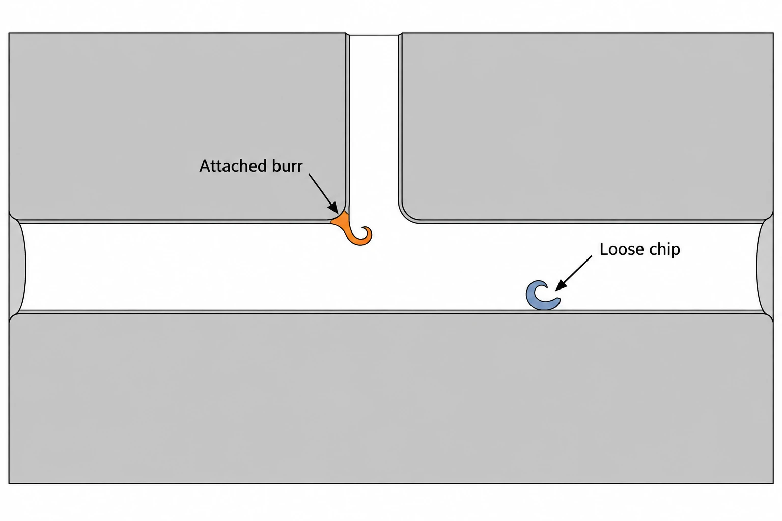
Specify internal deburring by the intersection to be treated, the edge condition required and the evidence needed to accept it. A general “deburr all edges” note does not tell a supplier how much material may be removed inside a fluid-control block, or how an inaccessible junction will be checked. Keep attached burrs, edge geometry and loose-particle cleanliness as separate acceptance items.
The difficult edge is often where one drilled passage breaks into another. Its boundary is curved, partly hidden and potentially close to a sealing or metering feature. Removing more material is not automatically a better result.
Deburring does not automatically create a specified chamfer
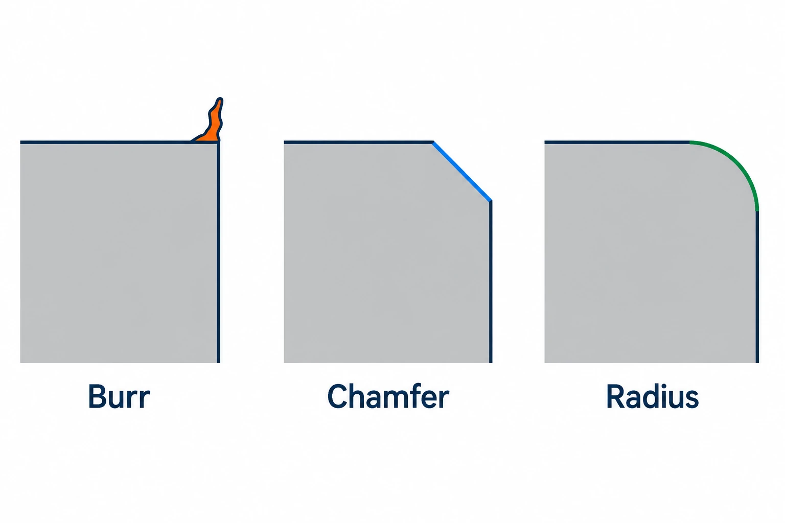
Deburring removes unwanted projections left by machining. An edge break removes or softens a sharp transition; a specified chamfer or radius defines geometry. These requirements can coexist, but one process description does not establish all three.
| Requirement | Define on the part | Acceptance evidence |
|---|---|---|
| Residual burr condition | Named intersections; permitted projection and attachment condition | Edge inspection capable of resolving the specified condition |
| Edge geometry | Allowed break, chamfer or radius; surfaces to preserve | Suitable dimensional or profile evaluation |
| Loose-particle cleanliness | Wetted areas, extraction method and particle limits | Agreed cleanliness test and report |
| Component function | Required flow, leakage or other functional criteria | Specified functional test; separate from edge inspection |
ISO 13715 addresses the indication and dimensioning of edges whose shape is undefined. Its public scope distinguishes these from edges with a specified geometric form. [1] A standard reference still needs the applicable drawing requirements; it does not choose an acceptable burr height for a particular valve or manifold.
Relate those requirements to the component’s material, interfaces and service conditions, as outlined in the materials and design guide. Avoid rounding a functional edge merely because adjacent handling edges need a break.
Choose a process that reaches the actual intersection
Review the main bore and cross-bore diameters, intersection angle, offset, depth and available approach directions. A tool that handles the external entrance of a straight hole may not reach the full internal intersection. HEULE’s X-BORES technical overview distinguishes solutions for different cross-bore arrangements rather than treating them as one tool-access problem. [2]
| Process family | Potential fit | Qualification focus |
|---|---|---|
| Dedicated mechanical deburring | Intersections with a workable tool path | Full edge access; secondary burrs; remaining profile |
| Electrochemical deburring | Selected internal edges in electrically conductive parts | Electrode/electrolyte access; controlled removal; subsequent cleaning |
| Thermal deburring | Suitable materials and burr geometries reachable by process gas | Material response; protected features; oxide removal |
EMAG describes electrochemical removal at the workpiece using an electrode and electrolyte. Extrude Hone explains thermal removal by oxidation and the oxide residue that remains to be removed afterward. [3] [4] These are process options to qualify for the component, not interchangeable finishing labels or a claim that every machine shop provides them.
For CNC milled blocks with intersecting holes, include deburring in the manufacturing sequence. Later drilling or thread-making can create a new edge condition; a treatment performed earlier cannot establish the final result at that junction.
Show which internal edges the inspection actually covers
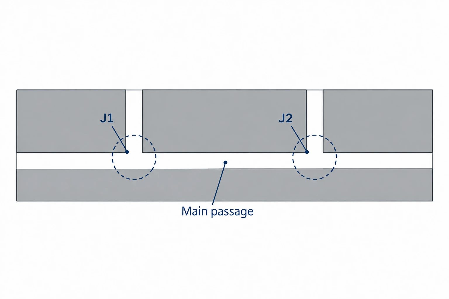
A useful inspection plan identifies the junction, access port, viewing direction and edge region to be evaluated. For a hypothetical block with two cross-passages, label the intersections J1 and J2. Record coverage for each; a clear image of J1 does not establish the condition at J2.
Where feasible, a borescope can support inspection, but the probe must fit and the optics must reveal the relevant edge. Plan additional positions or views when the far side is hidden. If the required region cannot be resolved, change the inspection approach or obtain an approved design/process solution before release.
Seeing a projection and measuring its height are different tasks. Evident’s guidance on videoscope measurement explains how distance, optics and the measurement setup affect results. [5] A conventional unscaled photograph is not a dimensional acceptance report. Use a qualified measurement method when a numerical edge limit controls acceptance.
Part coverage and feature coverage also differ. Checking every component does not help if the method misses the same hidden edge on every one. Agree both the lot-inspection scope and the internal regions covered. The precision machining and inspection scope should connect each requirement to suitable evidence, rather than relying on an equipment list.
Verify cleanliness after deburring and handling
Deburring can leave removed metal, process residues or contamination from handling. Cleaning has to reach the relevant passages and remove the specified contamination. Protect that condition through any later inspection, plugging, packing and assembly operations.
ISO 16232 provides methods for determining and documenting particulate contamination on relevant road-vehicle components. It does not set universal cleanliness limits, and its scope excludes film contamination such as oils and grease. [6] Where it is specified, the component’s cleanliness requirement must still identify the limits and inspection conditions. Other applications need their own appropriate specification.
A particle test evaluates contamination recovered under its agreed extraction method. It is not proof that every attached burr has been removed. Conversely, an internal visual inspection does not quantify the particles that may remain elsewhere in the passage network.
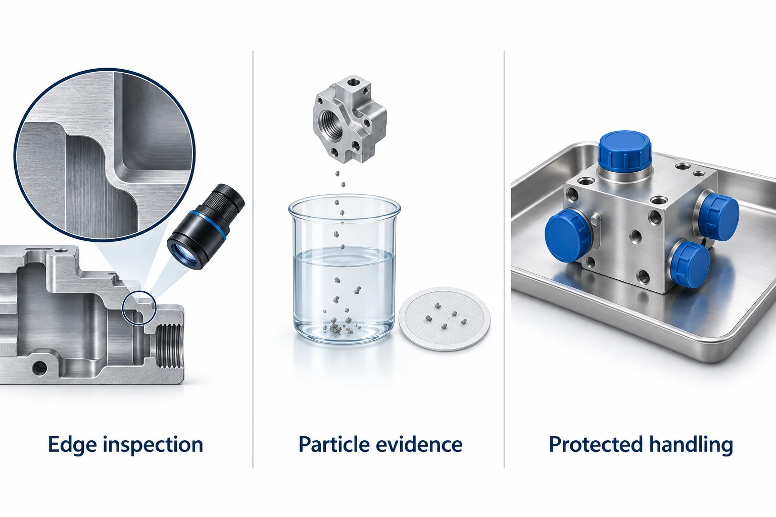
Make the accepted condition reproducible
For each critical junction, the release record should connect its drawing identifier to the applicable edge requirement, inspection method, coverage and result. Retain representative images where useful, with the part or lot identity and orientation. Record unresolved areas as unresolved, rather than treating missing visibility as a pass.
Include the section view or marked model, protected sealing and metering features, final edge limits, cleanliness specification and required records in the CNC machining RFQ. This lets the supplier price the actual removal and verification work, and gives receiving inspection the same acceptance basis.
Internal deburring questions
Can compressed air or flushing prove that a cross-hole is burr-free?
No. Removing loose material does not establish the condition of an attached edge. Use the agreed edge inspection as well as the required cleaning and cleanliness checks.
Should every internal edge have the same chamfer?
No. Sealing, metering and flow features can require different geometry from ordinary handling edges. The drawing should define the relevant treatment and any areas that must retain their specified profile.
Does passing a pressure or leak test prove that all burrs are removed?
No. It establishes the result of that functional test under its stated conditions. A residual projection can remain without causing a leak during the test, so edge acceptance still needs its own evidence.
Is there a universal acceptable burr size for a machined fluid block?
No. The limit depends on the feature’s function, downstream sensitivity and inspection capability. Define the part-specific requirement and how it will be verified; neither a general deburring note nor a cleanliness-standard number supplies that limit.
Technical sources
- ISO. ISO 13715:2017 — Edges of undefined shape, public scope of indication and dimensioning.
- HEULE. X-BORES: Customer-specific deburring solutions for intersecting bores or crossbores. Tool-family applications and access considerations.
- EMAG. The CI machine from EMAG ECM: A Highly Effective Solution for Deburring Complex Components, September 14, 2020. Electrochemical removal at internal intersections.
- Extrude Hone. Thermal Deburring Technology (TEM). Oxidation mechanism and follow-on oxide removal.
- Evident. Advancements in Remote Video Measurement: Get More Precision from Farther Away. Optical measurement setup and distance considerations.
- ISO. ISO 16232:2018 — Cleanliness of components and systems, public scope, exclusions and part-specific cleanliness limits.



