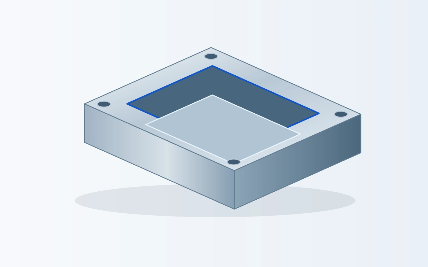
Cavity inserts
Recessed forms, parting lands and locating faces on one insert. Identify which surfaces shape the molded part and which fit the surrounding holder.

Request machining for mold inserts, cores, slides and support plates to your released component drawings. Define the locating fits, material condition and finishing requirements for each part.
Recessed forms, parting lands and locating faces on one insert. Identify which surfaces shape the molded part and which fit the surrounding holder.
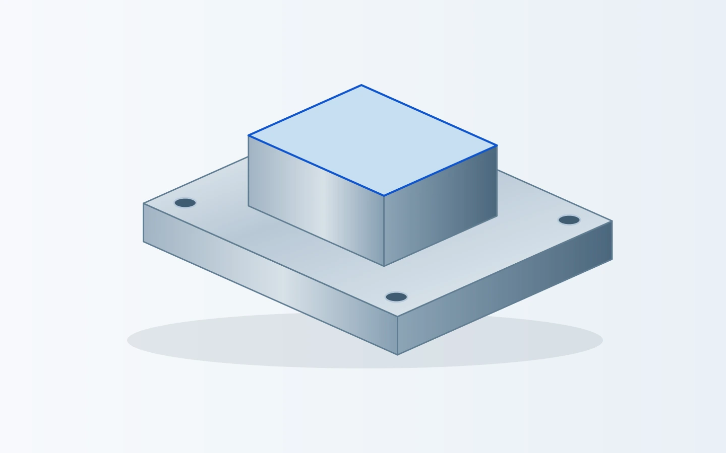
Raised forms with shoulders, mounting features and clearance around the core. Include the working geometry, datum faces and any areas to leave for later fitting.
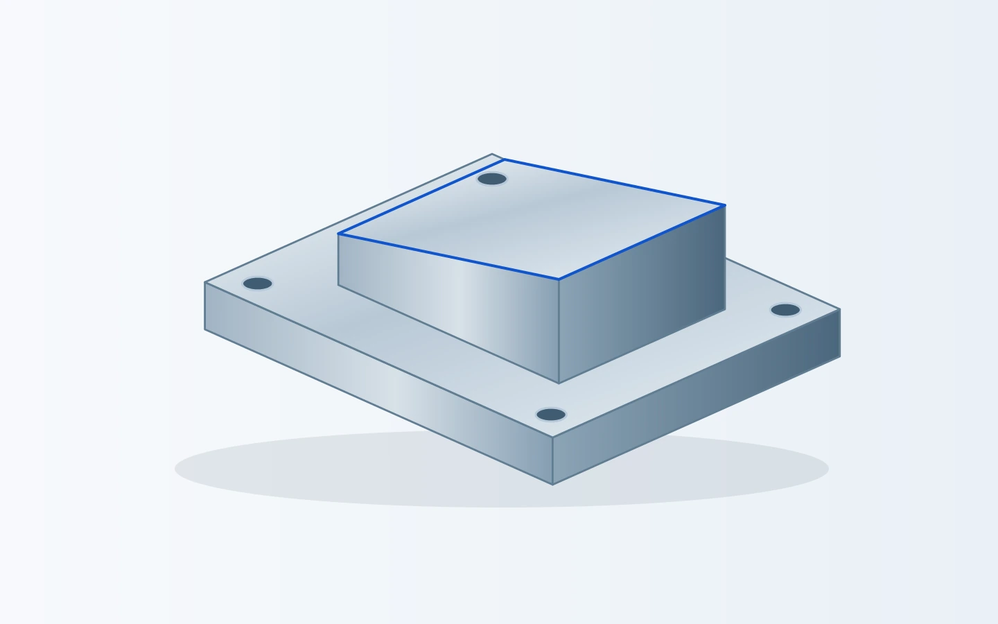
Forming details carried by a moving component. Send the slide or lifter detail with the mating guide surfaces and assembly reference, not just the molded feature.
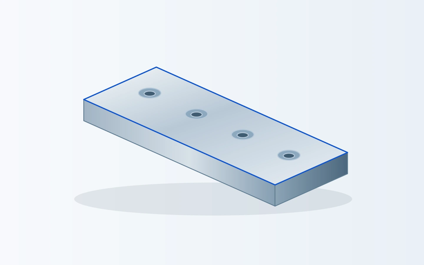
Sliding faces, locating steps and fastening holes. Specify thickness, parallelism where required, material condition and the surfaces that need grinding or coating.
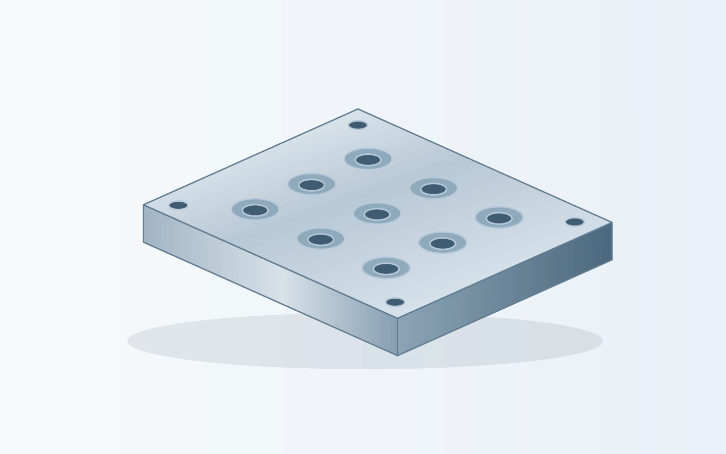
Plate pockets, bores and hole patterns that locate other components. The plate revision and hole coordinates need to agree with the assembly being built.
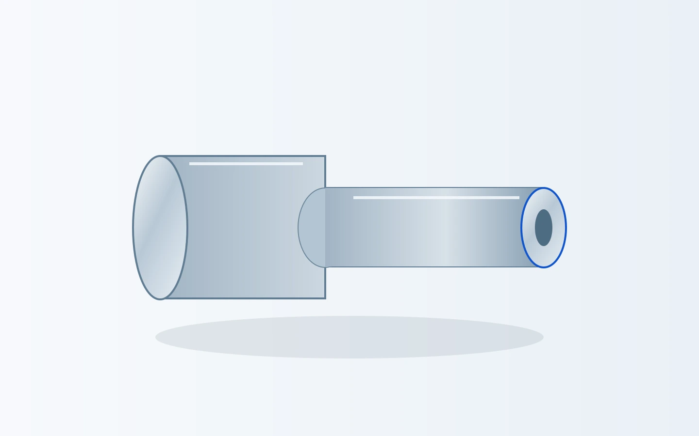
Round components with shoulders, bores or shaped ends. Define fit lengths, final end geometry and the reference used to inspect the turned and finished features.
No components match this search.
These component types can be discussed against your released drawings. The machining scope covers individual components; complete mold design, assembly and molding trials are outside this scope.[1]
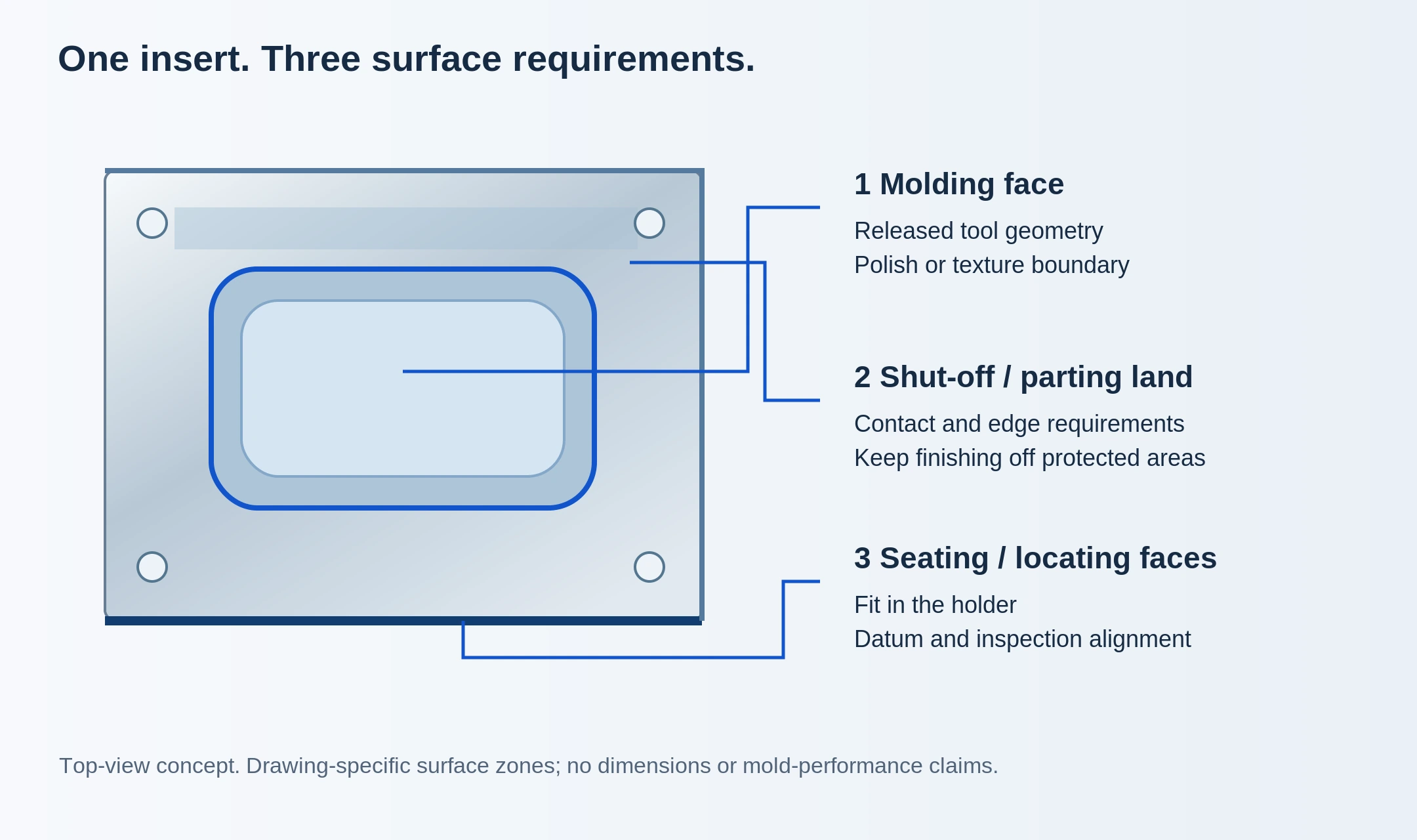
Use the released tooling model and a dimensioned component drawing. Identify any shrinkage allowance, draft and intentional stock already built into the tool geometry. A model of the plastic product alone is a different starting point; your mold designer must define the component to manufacture.
Include the mating pocket, seating shoulder and locating features when their relationship matters. Mark shut-off lands, fitting dimensions, datum faces and surface boundaries on the drawing.
For a set of inserts, list the quantity for each part number and cavity position. Mark mirrored versions and any handed features. For a replacement, distinguish the intended nominal geometry from wear, repairs or fitting changes on the old part.
Milling prepares the block, seating features and accessible cavity or core surfaces. Deep corners and narrow ribs need a tool-access review: cutter reach, holder clearance and remaining stock affect the finishing route. A staged roughing and finishing plan helps control the stock left on the profile.
[2]A conductive insert may need sinker EDM for a blind detail or wire EDM for a suitable through-profile. Agree who supplies sinker-electrode geometry and electrodes, or prepares wire-EDM start holes where needed. Specify the required surface condition after EDM and any subsequent finishing.
[3]Round cores and sleeves may begin with turning; specified fits or plate faces may need grinding. Keep these dimensions tied to the same datum scheme as the forming details. Any specialist finishing operation and its inspection will be identified in the quoted scope.
Some mold steels are supplied prehardened. They can change the route by avoiding a separate through-hardening operation where the design permits. Send the exact supplier grade and delivery condition; “P20-type” alone does not settle the purchase specification.
[4]For H13 or another specified tool steel, provide the approved material specification, incoming condition and required final hardness. Identify any areas intentionally left for finish machining after treatment, and name the party responsible for treatment records.
A corrosion-resistant grade may be specified for the molding environment, cooling circuit or required finish. Polishability is grade-dependent. Name the actual steel, not simply “stainless”; the supplier data and project requirements need to match.
[5]Material availability is confirmed against the specified grade and condition. Changes to grade or hardness require an approved drawing or purchasing revision.
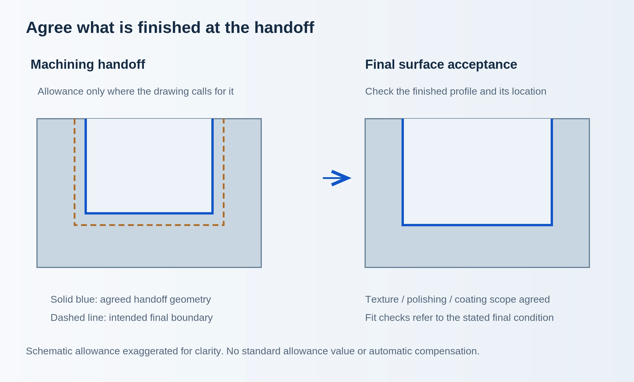
For a blank going to your heat treater, EDM shop or finishing specialist, mark the surfaces that stay oversize and how the allowance is measured. Keep a separate set of handoff dimensions where needed. A general note such as “leave stock” is not enough for a cavity with several different finishes.
Agree which datums, lifting or clamping features are already finished, and which stay available for the next setup.
For finish-machined inserts, state which cavity, seating and hole dimensions must be complete at delivery. Identify deliberate fitting stock rather than mixing it into the final-size drawing. Specify whether measurements apply before or after any listed coating or other treatment.
A finish-machined delivery can still go to another shop for polishing or texturing. That later operation must be listed separately.
A molding face, parting land and locating side do not need the same treatment. Mark the polish or texture boundary and use the approved finish specification or reference sample. Include protected edges and areas that must not be polished, rounded or coated.
Confirm the finishing specialist and acceptance method. A surface roughness value alone does not describe every visual or optical requirement.
Show the drilled route, depths, connections and thread specifications. Define deburring and cleaning at intersecting holes. If a leak or pressure test is required, state its method, conditions and acceptance criteria in the order.
Include the relevant assembly section and the intended pin or sleeve reference. Retainer thickness, shoulders and hole alignment can affect how the component fits the mold. Tell us whether the order covers a finished custom part or modifications to a specified standard blank.
Venting is part of the mold design, not a generic groove depth that the machining supplier should guess. Supply the approved vent details, shut-off areas and protected edges. These details need to survive deburring and surface finishing.
[6]A component inspection report should show which revision was checked and how the part was located for measurement. Keep mold trials, molded-part approval and component dimensions as separate acceptance steps; they answer different questions. The quote should identify the inspection methods available for your features.
| Feature | Drawing requirements | Records and checks |
|---|---|---|
| Seating and locating features | Fits, faces, dowels, geometry | Mating-part and datum measurements |
| Core and cavity | Model revision, profile, local details | Accessible measurement areas and alignment |
| Material and treatment | Grade, supplied condition, final hardness | Material and heat-treatment records |
| Molding and shutoff surfaces | Finish, boundaries, edges, final condition | Appearance, texture, dimensional checks |
| Cooling passages | Location, depth, connections, test requirements | Agreed cleaning and leak checks |
| Sets and replacements | Part, revision, cavity number, quantity | Component reports and packing identification |
Send the component model, drawing, bill-of-material position and quantity. We will separate material supply, machining, heat treatment, EDM, finishing and inspection in the proposal, including any work assigned to a partner.
Provide current dimensions, material and treatment records, and remaining stock on the required surfaces. A hardened or partly finished insert needs a different review from a raw block. Incoming condition and responsibility for the supplied blank should be agreed before dispatch.
Send the current component revision, cavity identification and mating details. Photos and an old insert can help identify damage, but wear should not become the new nominal size. Any drawing recovery, redesign or on-tool fitting must be agreed as additional work.
Deep ribs, small internal details, interrupted faces and difficult tool access can add tools, electrodes or setups. The amount of polishing or texturing also matters. Mark only the surfaces that require the specified finish, rather than applying one blanket note to the whole part.
A rough insert for your next operation is a different scope from a hardened, finished and inspected component. Treatment, specialist processing and the required reports need time in the schedule. Give the date you need the component at your mold shop.
Quote initial components and spare sets separately. Identify mixed revisions and mirrored pieces in the quantity list. On repeat orders, reference the approved drawing and finishing specification; an old purchase-order number alone may not capture the latest fit correction.
This service covers individual mold components made to released component drawings. Full mold design, mold-base assembly, hot-runner integration, mold trials and molded-part production are outside this component-machining scope.
Send the insert model, dimensioned drawing, material and required final condition. Include its locating fit and the molding-surface requirements. The review will establish which machining and finishing operations can be quoted for that component.
It can start a discussion, but it does not fully define the mold component. A tooling model needs the approved shrinkage, draft, parting and insert geometry, along with mounting details. Those design decisions must be released before a final component-machining quote.
Yes, that can be an appropriate route for conductive tooling material. Accessible areas may be milled while selected blind or through-features use EDM. The drawing review must settle access, electrode or start-hole responsibility and the delivery surface condition.
Start with the grade and condition approved by your mold designer. Prehardened, hardening and corrosion-resistant mold steels address different needs. Provide the exact material specification and required records; a proposed alternative should be reviewed before it is purchased.
Tolerance feasibility depends on the feature, material, size, treatment and measurement method. Send the drawing with applicable general tolerances and local limits. The quotation should confirm the critical requirements and inspection scope.
Yes, you can request a machining-only review. Include the current blank dimensions, material condition, treatment history and remaining stock. Acceptance of the supplied blank and the exact operations to perform must be agreed before work starts.
Only the operations listed in the quote are included. Specify the surface boundaries, grade, required condition and finish reference. Identify any approved specialist and whether acceptance applies before or after its operation.
A replacement inquiry should include the intended nominal drawing and its revision, the cavity position and the mating references. The old part is useful evidence of wear or modification, but reproducing that worn shape may repeat the problem. Drawing recovery or fitting work needs its own agreed scope.
Send the component CAD model and drawing, part and mold numbers, revision, material, quantity and delivery date. Add the locating fits, finishing boundaries and inspection requirements. For a multi-part order, attach an itemized list with the quantity and revision for each component.
A released component drawing is the best starting point. Include the delivery stage, mating references and any work performed by another specialist. Leave unknown values open rather than guessing a fit, hardness or finish grade.
For several components, attach a list of part numbers, revisions and quantities. The CNC machining RFQ checklist explains how to organize the drawing package.
References for mold-component terminology, machining processes and material selection. Confirm the component requirements, processing responsibilities and inspection scope in the quotation.