Skip to content
VETCNCCNC MANUFACTURING
Off-white insulating support strip, pocketed mounting block and flanged sleeve on a dark surface

PBT CNC
Machining

Compare PBT Stock Data

Custom PBT Supports, Bushings and Guide Components

6 component types

Insulating connector supports

We mill support strips with repeated openings, mounting faces and end fixing holes. Their spacing positions the inserted components while the remaining polymer separates neighboring openings. The strip is supplied to the defined geometry and stock requirement.
Flanged insulating bushings

A flanged sleeve combines a locating diameter, open bore and axial seating face. We turn these interfaces around the component axis, retaining the flange and shoulder needed to locate it in the surrounding assembly.

Profiled guide blocks

Open channels and local steps guide a sliding member without enclosing its entire length. We mill the running profile and its mounting holes from the specified reference faces, keeping clearance surfaces separate from the intended contact faces.

Axial spacers and locating rings

PBT rings separate adjacent components or locate a sleeve along a shaft. The bore clears or locates the mating feature; the two end faces establish the axial separation. A local shoulder can provide a second locating diameter.

Fixture contact nests

A machined nest supports a component on its defined curved or stepped surfaces. Mounting holes position the nest on the fixture, while the contact profile locates the workpiece. Access reliefs leave room for loading and removal.

Guide rollers

We turn rollers with a running band and central bore. The drawing relates the running surface to the bearing or shaft interface; grooves, end reliefs and axial shoulders are included where they serve the guiding arrangement.

VETCNC supplies drawing-defined PBT milled and turned components. The selected stock formulation, working interfaces and included inspection define the order; electrical, chemical or other application acceptance is specified for the actual assembly.

PBT Stock Formulation and Reference Properties

Unfilled PBT for defined mechanical geometry

Where a sliding counterface is sensitive to glass-fiber abrasion, an unfilled PBT product is the relevant starting comparison. Its actual load, speed and wear data still determine suitability; adding reinforcement for stiffness can change the contact behavior. [2]

Selection focus
Sliding-contact requirements and the chosen unfilled product’s wear behavior.

Glass-fiber-reinforced PBT stock

Ensinger positions TECADUR PBT GF30 for rigidity and creep resistance under sustained static loading. Its glass fibers can abrade mating surfaces, making that formulation less suitable for sliding contact. The reference table identifies this specific stock product. [1]

Selection focus
Static support stiffness and creep behavior, with the mating-surface tradeoff.

Rod for sleeves, rings and rollers

A round blank provides material around a central bore and the outer running or locating surface. Its starting diameter must cover the finished envelope and machining allowance, including any larger flange rather than only the sleeve body.[2]

Selection focus
Enough round stock for the largest retained flange or running diameter.

Plate for support patterns and guide profiles

Plate suits repeated hole rows, equipment pockets and guide channels. The starting thickness covers the deepest retained step and final support face. A plate blank also lets the pattern and its mounting references be machined together.

Selection focus
The support face, pattern envelope and material left under the profile.
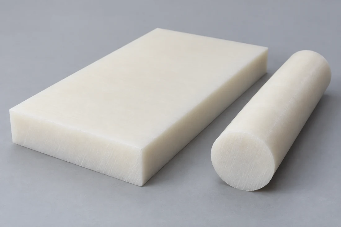
Unmarked white polymer rod and rectangular plate cut blanks
Plate blank envelope around a four-opening support pattern, highlighting retained webs

Read a stock test result at its stated condition

Strength, stiffness and elongation describe different responses. The producer lists a test speed beside each mechanical value; keep that basis with the named stock when comparing products rather than combining the largest number from different formulations. [1]

Reference data characterize the identified stock product; the drawing defines finished-part acceptance.

TECADUR PBT GF30 natural — producer reference values
PropertyValueTest basisUseful distinction
Density1.46 g/cm³Producer stock pageMass estimate for this product
Tensile strength46 MPaDIN EN ISO 527-2; 50 mm/minShort-term test response
Tensile modulus3,400 MPaDIN EN ISO 527-2; 1 mm/minStiffness reference
Elongation at yield / break5 / 6%DIN EN ISO 527-2; 50 mm/minTwo distinct endpoints
Flexural strength78 MPaDIN EN ISO 178; 2 mm/min, 10 NBending test response
Water absorption, 24 / 96 h0.02 / 0.04%DIN EN ISO 62; 23°CSeparate immersion durations
Reinforcement identityPBT GF30Named stock formulationDo not substitute a generic PBT callout

Source: Ensinger, TECADUR PBT GF30 natural product page, read 3 November 2026. Values characterize the named stock product at the listed test conditions; finished-part limits remain drawing-defined.

CNC Milling and Turning PBT Interfaces

Polymer plate supported beneath its retained section with two local clamps

Repeated openings and pocket floors

We machine the opening row from a consistent coordinate frame, then relate it to the fixing holes and support face. Retained webs and the floor beneath a pocket need support during cutting so that clamping does not temporarily flatten a flexible section.

Bores, flanges and axial seats

Turning establishes the bore, outside diameter and axial seat around one axis. The finishing cuts follow the retained flange and wall section; a thin sleeve is supported without relying on enough chuck pressure to distort it.

Heat and tool condition during removal

Sharp tools, chip clearance and a suitable removal sequence limit rubbing and concentrated heat. Major one-sided removal can release stock stress, so the final working surfaces are established after the principal material has been removed. [3]

PBT Hole Patterns, Seats and Running Surfaces

Flanged PBT sleeve and its mating interfacesConceptual sleeve section separating the locating outside diameter, central bore and axial flange seat. The component drawing defines their individual limits.Outer locating interfacePBT sleeveMating shaftInterface concept
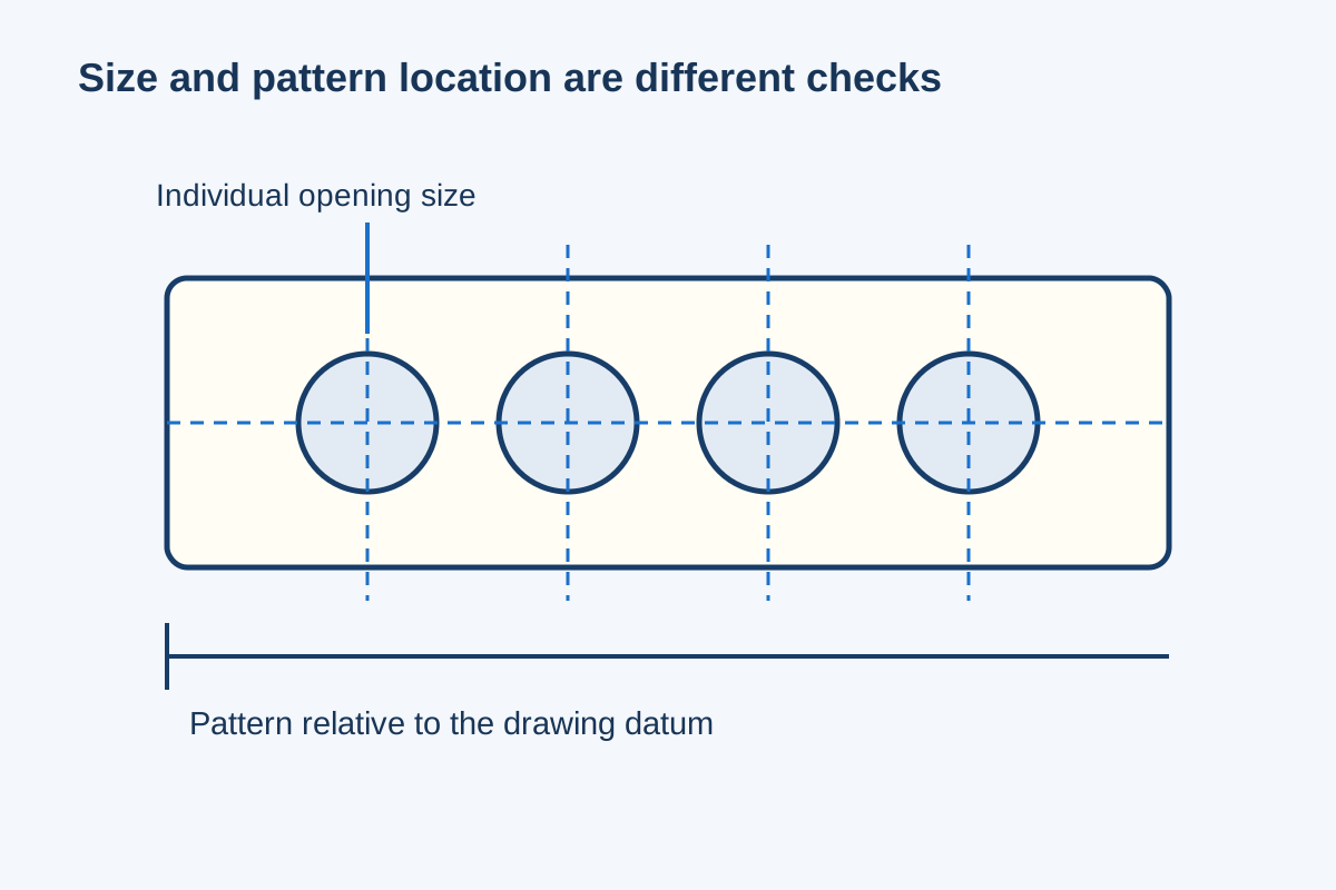
Size, position and face relationship are separate acceptance results.
PBT component features and their acceptance basis
FeatureRequirementFinal conditionVerification
Support stripOpening size and pattern-to-datum relationSpecified released/mounted stateSize plus positional relationship
Flanged sleeveBore, outside fit and axial seatDrawing support conditionDiameter and face relationships
Guide blockWorking profile and mounting referencesAfter edge finishingProfile and location
Guide rollerRunning band relative to bore axisSpecified assembly referenceRunout and contact profile

A feature-size limit does not by itself establish its position or relationship to another surface. Inspection follows the drawing datums and final support condition.

Quote the PBT Features That Control the Assembly

We identify the opening pattern, sleeve seat, guide profile and running band that matter for the component. Section thickness, stock formulation and access determine the machining and measurement route for those features.

Design Details for PBT Supports and Guides

Material between neighboring openings

Closely spaced openings leave webs that must remain intact through machining and assembly. The opening shape, pitch and outside edge distance act together; increasing a hole without moving its neighbor also reduces the intervening section.

A seat beneath the fastener

The fastener bears on the local support face. A flat bearing seat or specified washer arrangement distributes that contact without using the thin edge of a nearby pocket as the support. The assembly drawing controls the final fastener arrangement.

Internal corners and mating clearance

A milled pocket retains an internal cutter radius. A local corner relief can clear the inserted component while leaving the principal locating walls in place; widening the entire pocket would change all of those locating interfaces.[3]

Access to the contact surface

Guide profiles need enough access for the cutter and for the defined inspection method. Open relief beyond the working contact can simplify finishing, while an enclosed recess may require a different setup or tool reach.

Discuss Part Requirements

PBT Components for Insulation, Location and Guidance

Separating neighboring mounted components

A support strip holds the required spacing between mounted items and provides their attachment geometry. Electrical separation depends on the complete design, environment and specified acceptance, rather than the presence of a polymer strip alone.

Locating an instrument component

A pocket or shoulder registers the instrument body while mounting features position the support within the equipment. The locating surface, connection opening and removal clearance serve different installation tasks.

Guiding a moving component

A block or roller controls the contact path of a moving item. The guide profile and running arrangement are selected for the actual counterface, load and duty; a material tensile value is not a bearing-load or wear-life rating.

Supporting a workpiece in a fixture

A nest contacts the intended reference areas while leaving access to other faces. Local replaceable contact pieces can preserve the fixture body when the supported component changes, without turning every surface into a locating constraint.

PBT Working-Face and Edge Finishing

Conceptual circular opening separating a local edge break from the functional bore

Specified machined contact faces

The running or locating face retains its required texture and profile. A cosmetic hand-polish can change contact height or round an edge, so additional finishing is defined around the working surface rather than an appearance-only target.

Local edge breaks

Deburring removes the loose rim at an opening without enlarging its functional bore. A permitted chamfer belongs on its defined edge, leaving the adjacent seat or pattern web intact.

Openings beside a thin web

The finished rim remains continuous where it supports an inserted component. A chip or torn edge is evaluated against the drawing, rather than blended across the whole opening until the local defect disappears.

Clean contact and protected handling

We clear machining debris from accessible pockets and openings, then protect the working faces during packing. Cleanliness requirements beyond that machining scope identify the required cleaning method and acceptance.

PBT Material, Dimensional and Functional Acceptance

Four-hole support pattern with individual size and datum-related position indicated separately

Stock identity and formulation

The material record identifies the ordered PBT product and any required reinforcement or source restriction. A visually similar stock replacement is a proposed material change, even when the component drawing has not changed.

Pattern, seat and profile relationships

Dimensional inspection follows the features used to accept the assembly: opening positions, shoulder depths, support-face relationships and guide profiles. The method must reach the relevant surfaces rather than only the outside envelope.

Electrical or application-specific tests

A dimensional report establishes geometry. Dielectric, leakage and other functional results come with their own specified configuration, test method and acceptance limits when they form part of supply.

What Changes the Cost of PBT CNC Machining?

Exact stock and retained envelope

Named stock or source restrictions affect procurement. A large flange can set the rod diameter for a slender sleeve; a deeply pocketed plate consumes material that does not remain in the final support.

Opening count and tool access

Many repeated openings add cutting and inspection time even when the outside shape is simple. Deep recesses, back-face features and small tools can require extra setups beyond an open pattern machined from one side.

Working finish and included records

A specified contact finish, local rim inspection or special cleaning step adds defined work. Functional tests have separate preparation and records, priced for the actual component and test arrangement.

Quantity sharing the same setup

Programming, workholding and initial checks are spread across unchanged parts made together. A new pattern pitch or stock formulation can require new preparation; quantity savings do not remove the work needed to establish that changed part.

From a PBT Assembly Trial to Repeat Supply

Check the actual mating stack

The trial verifies that the openings, seats and access suit the surrounding components. Assembly feedback identifies the particular interface to change before the remaining quantity is released.

Use the intended stock product

A representative trial uses the selected PBT formulation and working surfaces. A similar-looking part made from another polymer can answer envelope questions, while the response of the intended stock comes from a trial in that stock.

Release the working relationships

The accepted revision carries the pattern datums, support condition and final finish into production. Any separately required functional test is identified with that same part definition.

Retain the accepted repeat basis

Repeat supply follows the agreed stock product, geometry and acceptance records. A change in source or formulation is identified before it enters the repeat order so that its effect on the accepted component can be assessed.

PBT CNC Machining FAQs

Does low PBT water uptake mean it is suitable for hot-water service?

No. Low mass uptake and resistance to prolonged hot-water exposure are different properties. Ensinger flags a hot-water limitation above 60°C for the named GF30 stock, while GEHR also identifies PBT as sensitive to hydrolysis. The actual stock and wet-service temperature need to suit the application; the table is not an approval for steam or hot-water duty.

Can a water-absorption percentage be used directly as dimensional growth?

No. The percentage reports absorbed water by mass under the stated test. It is not a percentage increase in every component dimension. A close mating arrangement needs the relevant stock-specific dimensional behavior and exposure condition rather than adding the mass percentage to the bore diameter.

Does a flame rating for a PBT resin certify the machined component?

No. A resin or stock classification applies to its identified formulation and test basis, including any relevant specimen thickness. A different color, filler package or source is not automatically covered. The finished support or housing still follows the application’s required electrical and fire-safety acceptance.

Does a PET geometry trial settle a low-temperature PBT material choice?

No. Ensinger describes better impact resistance for the PBT polymer family than PET, particularly at low temperatures. That difference makes impact duty relevant to selection, while the limit for a given stock formulation and a finished part's allowable load come from a stock-specific assessment. A geometry trial and a stock-specific impact assessment answer different questions.

Is a machined molded blank the same starting point as a rod or plate?

No. Its available envelope, molded features and prior processing history are different. Machining may finish only selected interfaces on that blank, while rod or plate machining removes the surrounding stock to create the component. The blank identity and machining responsibility need to be part of that specific order.

Can a PBT part be bonded instead of mechanically fastened?

Bonding can be a design option. GEHR gives epoxy, cyanoacrylate and silicone adhesive examples for its PBT; bond strength for a particular assembly comes from testing that joint. The chosen stock, preparation, adhesive, joint gap and service exposure need to be compatible with the joint requirement.

PROJECT SUPPORT

Discuss Your PBT Component

Send the drawing and model, exact PBT stock formulation, quantity and required working-face finish. Include the assembly condition and any separately specified electrical, chemical or other functional acceptance so we can quote the defined scope.

PBT Stock and Manufacturing References

Named stock data and the machining, joining and exposure conditions used in this page.

  1. Ensinger — TECADUR PBT GF30 NaturalThe identified stock product, mechanical-test conditions and separate water-uptake endpoints.
  2. GEHR — PBT Stock ShapesStock-material context, hydrolysis sensitivity and adhesive-joining examples.
  3. Mitsubishi Chemical Group — Machinist’s ToolkitSupport, clamp distortion, heat and stock-stress mechanisms in engineering-polymer machining.
  4. Ensinger — PBT Material and Chemical Selection; UL Solutions — Plastics RecognitionPBT/PET impact context, exposure conditions, and material flame-classification thickness and color entries.
VETCNCCNC MANUFACTURING

Get a Quote

Upload Drawing

*Required fields

Acetal part geometry illustration

Enlarged part geometry illustration

AI-generated part illustration.

English
WhatsApp Email us

Tell us about your project

Share your requirements and we will get back to you by email.

PDF, CAD or ZIP · up to 20 MB