Straight adapters
Two different equipment interfaces can meet through a short machined adapter. We turn the connected bores, end features and wrenching section around the required connection axis. Each end retains its own sealing definition.
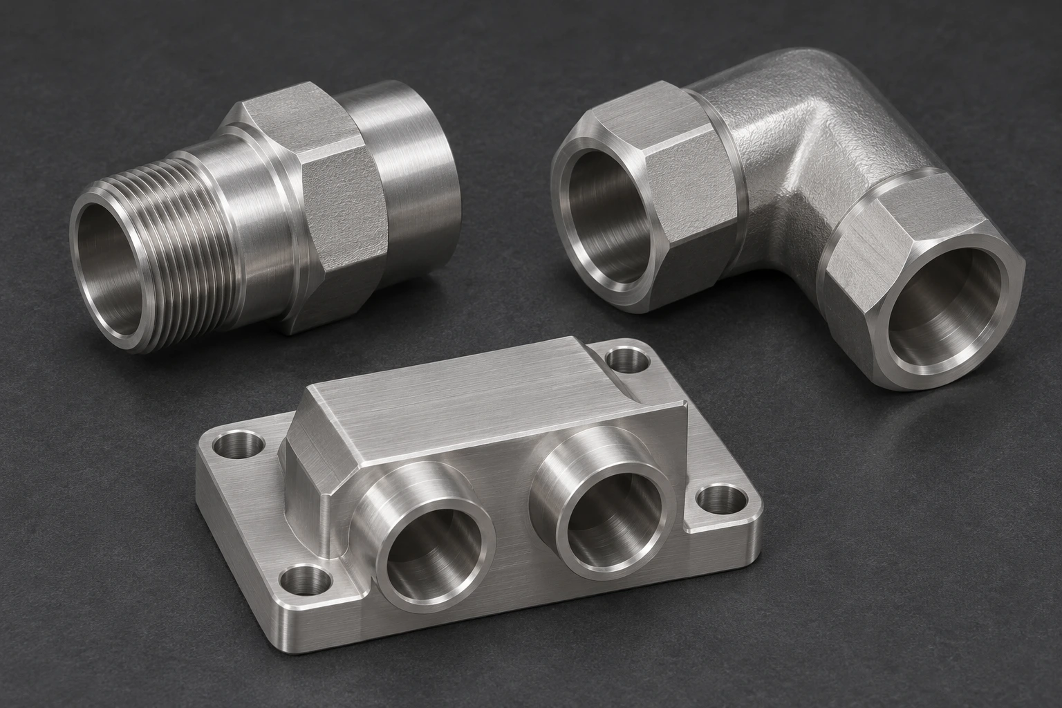
Two different equipment interfaces can meet through a short machined adapter. We turn the connected bores, end features and wrenching section around the required connection axis. Each end retains its own sealing definition.
An elbow changes the direction of an accessible passage. The machined body relates its two ports to the installed orientation while leaving the required material around the outside corner and port roots.
A shoulder and retaining thread locate the connection through a panel or support. The installed stack includes that panel and its retention hardware, with a usable connection projecting on each side.
A small body can combine a connection with its local equipment attachment. Its fixing face locates the opening in the receiving module. More extensive valve cavities and internal distribution networks belong to our separate manifold-block scope.
A closed body terminates the specified connection. Its thread retains the component; the selected thread seal, face or separate seal contact closes the opening. A shipping cap and an installed closure have different roles.
A connection body joins a measuring or monitoring device to its specified equipment port. We retain the instrument-side connection and its insertion envelope separately from the equipment-side mounting or sealing features.
A union body joins the selected mating ends while the defined retention arrangement brings their contacts together. Machining the body does not select the mating nuts, ferrules or seals on behalf of the connection-system designer.
A collar or nut holds the selected fitting body against its mounting reference. Its thread, bearing face and tool-access region belong to that retention task rather than becoming an unintended sealing contact.
No matching component forms. Reset the filters or discuss your drawing.

A corrosion-exposed fitting may use a specified stainless grade. The selected alloy, stock condition and mating materials stay part of the connection definition, and compatibility is assessed for the actual medium and assembly process.
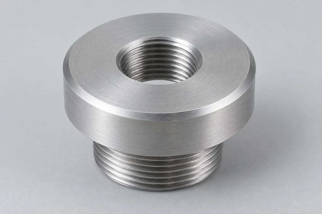
Steel can be selected for the released mechanical connection and its surface-treatment route. The usable thread, sealing contact and exposed exterior have different finishing needs. We account for the delivered coating state in their final dimensions.
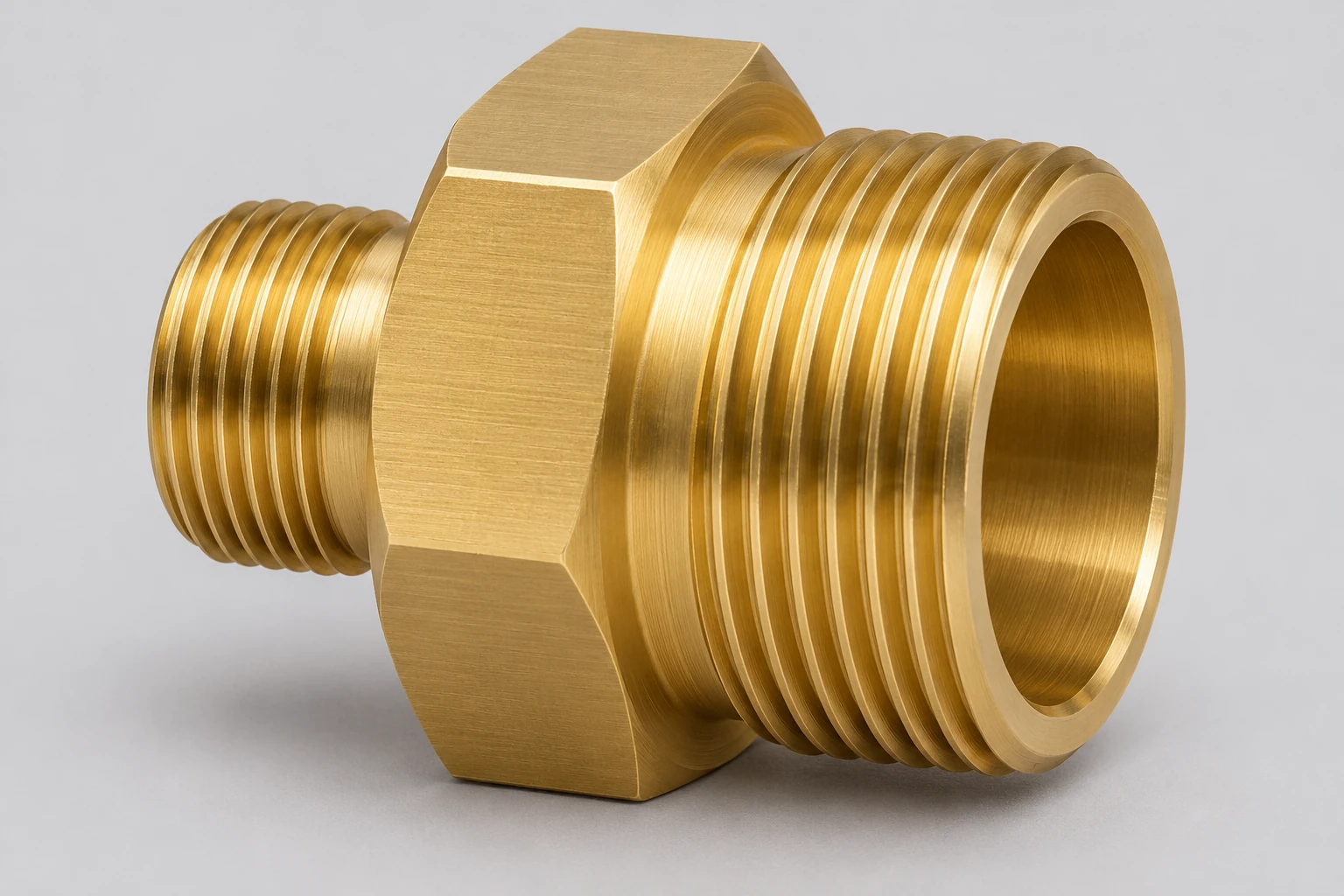
An approved brass or aluminum specification can provide a different component route. Round or hexagonal stock suits accessible turned forms; a supplied shaped blank may reduce removal around an offset body. Neither starting form establishes the finished connection rating.
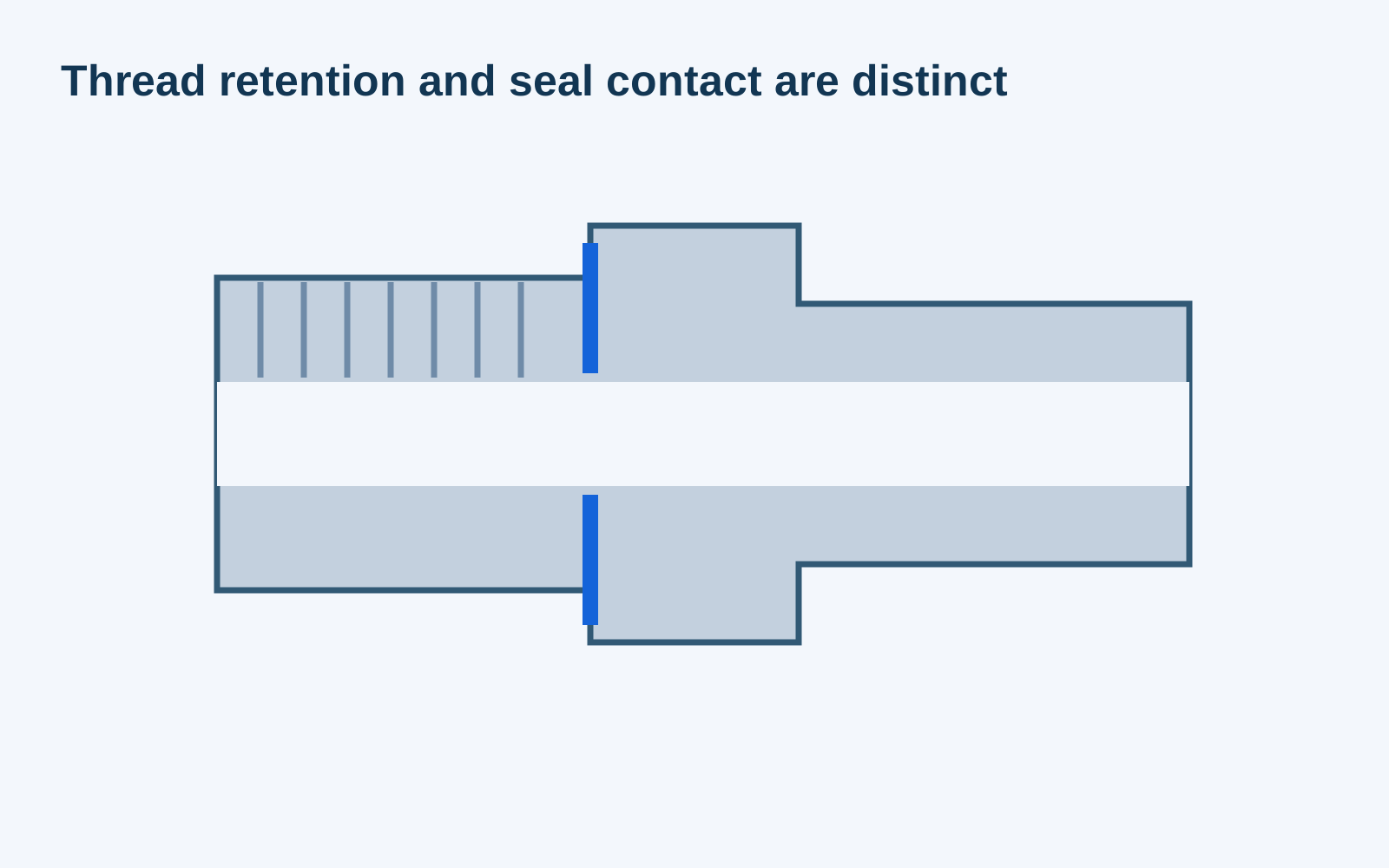
A thread standard defines its form; an end-connection definition also identifies the sealing geometry. Swagelok’s identification guide distinguishes those two references. We retain the specified seat, shoulder or seal housing alongside the thread, rather than selecting a connection by its threaded diameter alone.[2]
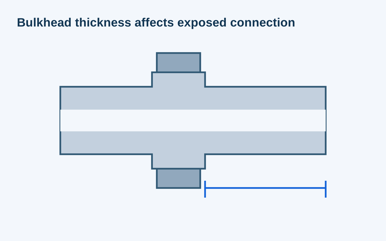
The two ends of an elbow need their required angular relationship after installation. A bulkhead body needs the intended projection through the actual support stack. Both installed relationships are defined on the drawing and checked as assembled conditions.

Wrench flats need reachable tool space while the mating end is engaged. The shoulder, locknut or separate retaining feature must seat without trapping another component. These access regions are part of the finished geometry around the connection.
| Selected thread | Pitch | Included thread angle |
|---|---|---|
| 1/8 NPT | 27 threads/in | 60° |
| R1/8 · ISO 7-1 | 28 threads/in | 55° |
| 1/4 NPT | 18 threads/in | 60° |
| R1/4 · ISO 7-1 | 19 threads/in | 55° |
| 1/2 NPT | 14 threads/in | 60° |
| R1/2 · ISO 7-1 | 14 threads/in | 55° |
Swagelok MS-13-77, pages 22–23. Fractions are nominal pipe sizes, not measured bore diameters. Matching pitch at 1/2 in does not make the thread forms interchangeable. These are identification references; the selected standard and component drawing govern manufacturing and inspection.

We machine accessible bores, shoulders and end features from the defined component axis. Where the second end needs another setup, the locating route carries that reference across the transfer instead of centering the second contact from an unfinished exterior.
An elbow or cross-port leaves an internal intersection as well as a visible entry. The cutting and deburring route needs access to that hidden edge before the component is closed or assembled. Local edge work preserves the specified seat and bore.
Wrench flats, mounting pads and other robust regions can provide holding contact around an irregular body. The route keeps those contacts clear of a delicate sealing land and avoids relying on a thin port extension to resist the cutting load.
A scratch across a sealing land has a different consequence from a tool mark on the exterior hex. We keep the specified contact geometry and texture distinct from the surrounding cosmetic surface.
Included coating, masking and final checks follow the released finish definition. A thread accepted before a deposited layer is not automatically the same finished thread; the manufacturing route preserves the required assembly contact after treatment.
Loose burrs and finishing residue do not belong inside an open connection. Cleaning and temporary protection follow the agreed delivery requirement, without treating ordinary component cleaning as a validated system-cleanliness result.
Part and revision marks belong where they remain usable without damaging the seat, usable thread or wrenching region. Temporary protection stays distinguishable from a closure intended to remain in the operating assembly.
Parker’s rail-vehicle component guide distinguishes water, oil and air applications and different fitting or coupling families.[3]
We check the specified thread and the related seating geometry as separate features. An elbow’s port direction and a bulkhead body’s shoulder distance are additional results tied to the component datums, rather than consequences of a thread gauge result.
The drawing defines the geometry of the supplied body. Any required assembly, leak, pressure or cleanliness acceptance has its own scope, method and limits in the quotation; it is not inferred from a satisfactory dimensional report.
The component record links the material, revision, finish and agreed acceptance. Railway project requirements may also govern supplier qualification and the receiving assembly. Those requirements stay explicit alongside the quoted machining work.

An initial component can establish tool access, projection and mating-end clearance in the receiving equipment. This installation check is separate from releasing the equipment’s operating performance.
The accepted fitting connects the specific equipment end and mating connection. A revision on either side remains linked to the fitting definition, including any retained hardware and supplied assembly state.
Adapters with different end combinations can look nearly identical. Part identification and separate packing keep the required ends together instead of asking an installer to distinguish them by eye.
Threads, sealing contacts and open passages receive suitable protection during handling. Packing prevents a heavy neighboring component from striking the exposed end or forcing debris into the bore.
Accessible turned stock can avoid unnecessary blank preparation. Offset ports, deep internal contacts and additional setups still add work. Repeat quantities spread programming and fixture preparation across more components, while the per-part finishing and agreed acceptance remain.
| Include | Required detail |
|---|---|
| Finished fitting | Drawing/revision, material/condition, quantities and units |
| Both connection ends | End-connection references, thread callouts, seal geometry and mating parts |
| Installed body | Port direction, support stack, wrench access, finish and supply state |
| Project acceptance | Dimensional records, supplier/project requirements and any separately included tests |
Agree a secure transfer method for confidential files.
The sample can establish accessible geometry, but wear or damaged threads can obscure the intended connection. We need an accepted definition of the original mating contacts before reproducing them. Matching the worn outline alone can carry its defect into the new fitting; a drawing or approved nominal interface resolves that difference.
A body is only part of that product. The locking mechanism, valves, seals and mating half determine how the coupling connects and disconnects. Our component quotation identifies the loose body and any expressly included assembly work.
No. ISO’s public abstract describes requirements for an organizational railway quality-management system across the supply chain. That is a different question from conformity of a particular fitting or acceptance of its receiving equipment. The project specifies the required supplier evidence and product acceptance.
That requires review of the complete connection for its new duty. The selected metal is only one element: retained seals, the mating system, temperature and fluid can change what is suitable. Parker lists rail water, oil and air applications separately. A dimensional match does not authorize moving the assembled connection between them.
No. Suitable bar stock or an available approved blank can be a practical starting route for a small accessible fitting. A shaped preform may reduce repeated removal for other geometries, but it brings its own preparation. We compare those routes for the actual component and quantity rather than assume every spare needs dedicated forming tooling.
Only if the revised installation is accepted. Extra length also moves the connected tube, hose or instrument and changes its projection from the support. That can alter nearby clearance, support or the space needed for removal. The complete installed arrangement needs to permit the extension, even when both connection ends remain unchanged.
Send the fitting drawing and both mating-connection definitions with the material, quantity and railway project requirements. We will quote the machined body, delivered finish and included acceptance.
Sources for thread identification, complete end connections, railway application families and quality-system scope.
We use Google Analytics to see how this site is used. Analytics cookies are set only if you accept. Privacy Policy
