Probe Adapters, Process Fittings and Mounting Hardware
Threaded probe-adapter bodies
A through bore receives the specified probe or sleeve while an external connection mounts the body. We machine the bore, retaining thread and adjacent shoulder as related features so the fitting positions the probe from the intended interface.
Through-bore mounting bushes
A bush guides a cylindrical probe through a panel or support. Its bore and seating shoulder establish the mounting position; it does not become a pressure-sealing assembly simply because the probe fits through it.
Reducing process adapters
Different inner and outer connections allow a selected instrument to meet an existing port. We preserve both connection definitions and the internal clearance between them, including the seat or sealing region at each end.
Union bodies and retaining nuts
A separate nut retains the fitting against its released mating body. We supply the identified body or nut with its thread, bearing face and required tool access; the parts included in the order remain explicit.
Flanged sensor mounts
A flange locates the probe bore from a mounting face and fastening pattern. Its register, gasket boundary and attachment details follow the selected interface rather than an assumed universal flange connection.
Offset and angled fitting bodies
An offset body places the probe connection away from the process-side axis or at a released angle. The intersecting passage, end position and surrounding installation clearance are defined with the two interfaces.
Insert and seal carriers
A separate carrier supports the specified insert or seal within the fitting. We machine its locating diameter, shoulder and entry edge so the retained part occupies the released position without substituting a generic groove.
Mounting collars and axial spacers
Collars and spacers set the position of a probe holder or surrounding support. Their accepted lengths and contact faces control the installed stack; clearance and split or fastening details follow the actual drawing.
No matching component forms. Reset the filters or discuss your drawing.
8 component formsWe supply drawing-defined sensor fitting components and mounting hardware, with the ordered material, surface condition and dimensional inspection. Sensors, ferrules, seals and mating hardware are included only when named in the quotation. Sensor electronics, complete pressure-assembly approval and hygienic-system qualification remain separate from machining the fitting.
The selected stainless grade and condition follow the process-side specification. Threads, seal lands and exposed passages are kept in that material definition, and compatibility is assessed for the actual medium and cleaning cycle.
Brass can be specified for threaded adapter bodies, nuts and mounting details. Its actual grade and any plating remain part of the supplied condition, while the project determines whether the alloy is acceptable at the wetted interface.
A dry-side collar, spacer or panel mount can use a different material from the process fitting. The design still accounts for the retained probe, tightening load and temperature; an external mounting material is not automatically an acceptable wetted substitute.
A process connection includes the released thread and the surface that forms its seal. The WIKA references below illustrate how instruments with the same broad nominal thread family can retain different axial and seating geometry. The machined part follows the complete connection drawing.
Position the probe from the installed reference
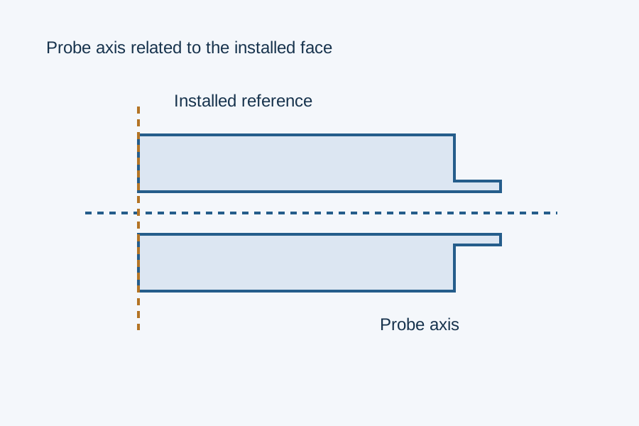
The probe bore, retaining shoulder and process-side face establish where the sensing region sits after installation. We relate these features to the specified datum instead of using the fitting’s outside length as a substitute for the installed position.
Retain access beside the fitted instrument
Hex flats, union-nut clearance and nearby side ports must remain accessible in the installed arrangement. A fitting that matches both thread callouts can still place its tool contact or surrounding body where the selected instrument cannot be fitted.
Process-Connection Dimensions Need Their Named Drawing
Instrument drawing dimension; not engagement turns
ANSI/ASME B1.20.1, ½ NPT
WIKA drawing L1 19 mm
Retain the selected port and installation definition
Source: WIKA IN 00.14, December 2025, pp.5–6. L1 and L2 retain the labels and scope of those pressure-instrument drawings, not universal thread-engagement lengths. The selected complete connection drawing defines the actual fitting.
Machine the Bore, Thread and Seating References
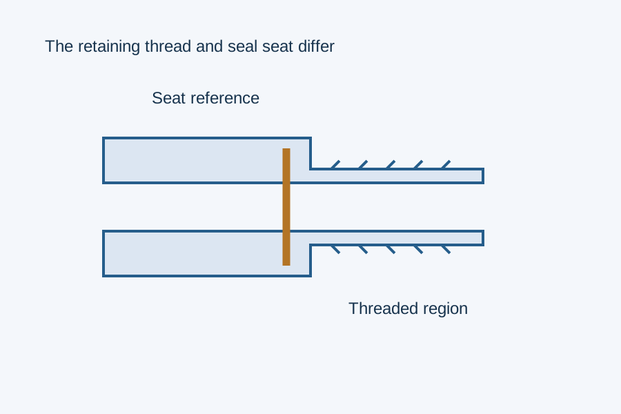
An open fitting bore and its adjacent thread shoulder
Turn the bore and related shoulders
We establish the specified probe bore, outside register and shoulder relationship through the fitting’s reference setup. A thin retaining section needs support through finishing so the released fit is not based on its clamped shape.
Complete the selected thread and sealing regions
The thread is made to its named definition while the seal land, entry relief and adjacent face retain their own dimensions. These features are inspected in the ordered final condition; a correct thread alone does not release an incorrect seat.
Add flats, angles and intersecting access
Milled flats and side connections follow the established fitting axis or mounting datums. Passage intersections are deburred with access to the internal edges, while the tool-contact region remains distinct from the probe’s locating surface.[1]
Protect the Probe Bore and the Working Seal Region
Keep entries free of damaging edges
Probe-bore entries and seal leads receive their specified edge condition. Removing a loose burr must not enlarge the guiding section or consume the shoulder that positions the insert.
Keep coating coverage explicit
Where plating or another finish is ordered, the drawing identifies threaded, seating and exposed regions. The accepted dimensions apply to that finished condition, including any masked bore or seal land.
Retain process-side cleanliness requirements
Record the required delivery cleanliness. If a particle or residue limit is specified, the order also defines how it will be verified.
Separate and protect finished contacts
Packing keeps seal faces, probe bores and threads from contacting other components. Any temporary shipping protection is distinguishable from a permanent plug or included assembly part.
Finished fitting surfaces are protected through packing; the order identifies any included seals, protective caps or mating hardware.
Inspect the Fitting’s Actual Mounting Interfaces
Thread and connection features
We check the named thread definition and its specified acceptance. The adjacent seat, shoulder, lead-in or sealing diameter remains a separate feature in the dimensional report.[2]
Bore, face and installed position
The probe bore, mounting face, register and axial dimensions are checked from the released datums. An offset fitting also retains its specified angle and relative port position.
Final component and assembly requirements
Material, finish and component identity remain associated with the inspection record. Any required leak, pressure, electrical or hygienic acceptance needs its separately agreed method, assembly state and responsibility; it is not inferred from dimensional results.
Probe axis, seating face and connection geometry have separate checks
First Fittings, Accepted Interfaces and Repeat Supply
Establish the actual mating definition
The first component follows the controlled sensor, probe-holder and process-port interfaces. A sample may help identify an arrangement, but worn sealing or retaining surfaces are not silently copied as nominal geometry.
Evaluate installation with the intended parts
Initial fittings allow the project to check probe location, tool access and surrounding clearance with the selected instrument and mounting point. Any change to an interface becomes a released drawing revision.
Keep finishing and dimensional acceptance aligned
Repeat manufacture retains the accepted treatment, masked areas and final inspection state. A plated or otherwise processed fitting is not released solely from measurements taken before that operation.
Keep similar connections identifiable
Part and revision identity distinguish fittings that look alike but have different internal threads, seats or axial lengths. Packing and records preserve that identity through assembly.
Cost follows interfaces and access
Programming and holding preparation are spread over quantity. Two different thread systems, deep small bores, angled ports, thin retained sections and extra finished-state inspection still add work to each fitting; its small outside size does not remove those operations.
Definition of the supplied sensor fitting component
Include
Relevant detail
Mating interfaces
Probe or holder drawing, process connection, seat and included hardware
Position and access
Bore and axial references, installation angle and tool clearance
Final material and acceptance
Grade/condition, finish regions, dimensional limits and separately defined tests
Supply identity
Part/revision, variants, quantities, included seals, ferrules or caps
Agree a secure transfer method for confidential files.
Your milled parts inquiry list
0 part lines in your inquiry
Part name / numberMaterial / exact gradeRevisionQuantity
Choose a milled part above or add a line for your own drawing. Expand each line to add pocket, hole and datum requirements.
Drawing review topicsNo review topics selected.
This list organizes your inquiry. Price, availability and the approved manufacturing specification come back to you from our engineers in the written quotation. Entries stay in this page unless you download them or submit them to a configured quote endpoint.
Custom Sensor Fitting FAQs
Is a 12 mm process sensor’s A-length its overall length?
No. Hamilton measures the A-length of its traditional 12 mm sensors from the base of the PG13.5 mounting threads to the electrode tip. For its refillable sensors, the reference is the base of the refillable chamber. The selected holder has to suit that A-length, since insertion position is measured from the stated reference.
Does a G 1¼ Ingold retaining thread establish a flush process connection?
No. Hamilton’s holder guidance also relates the O-ring position on the body to the length of the mating socket. That relationship establishes the seal at the inner vessel wall and avoids an unintended dead space. The retaining thread designation alone does not release the required socket and seal-position combination.
Can BSPT and NPT be substituted because both threads are tapered?
No. Parker’s thread-identification guide gives a 55° profile for BSPT and a 60° profile for NPT and explicitly states that BSPT will not substitute for NPT. The fitting must retain the specified complete thread system, even if two parts begin to screw together.
Does an industrial bolted flange make a sensor mount a sanitary connection?
Not by itself. Hamilton distinguishes its ANSI/DN industrial flanges from its sanitary process connections. A flush, cleanable arrangement follows from the hygienic connection specified for the installation. The actual connection and installation specification govern that choice.
Can a compression body for a 12 mm stem accept a ½ inch stem?
The selected compression interface must match the actual tube or stem diameter. Half an inch is 12.7 mm, so it is not the same diameter as 12 mm. Hamilton’s connection guidance makes tube size part of the ferrule-fitting match; tightening a different stem into the body is not an approved dimensional substitution.
Can the sensor case be used to tighten the process fitting?
Use the installation tool contact defined by the instrument manufacturer. WIKA’s process-connection guidance requires the spanner flats at the thread and says the case must not carry that mounting load. The fitting drawing and installed access should preserve the intended wrench contact rather than require force through the instrument case.
PROJECT SUPPORT
Discuss Your Custom Sensor Fitting
Send the fitting drawing and the relevant probe, holder and process-port interfaces, with material, final condition and quantity. We will quote the included component machining, finishing and inspection.
Original process-connection drawings, thread definitions and probe-position references used on this page.
WIKA — Information on Process Connections, IN 00.14, December 2025— Named pressure-instrument connection drawings, L1/L2 dimensions, seating variants and installation tool contacts.
Parker — Instrument Tube Fitting Installation Manual, Bulletin 4200-B4, January 2023— NPT, BSPT and BSPP thread identification and distinct sealing arrangements, printed pp.62–64.
Hamilton — What Type of Process Connection Does My Sensor Have?— Process-side connection families and their distinction from the electrical interface.
Hamilton — How to Measure Sensor A-length— Manufacturer-specific measurement origins for traditional and refillable process sensors.
Hamilton — Process Connection Options for Housings— Ingold seal/socket relationship, tube-size matching and sanitary versus industrial flange interfaces.