Fluid connector bodies
We turn connector bores, threaded ends, shoulders and wrenching details. The flow opening, attachment thread and sealing feature follow the released component drawing.
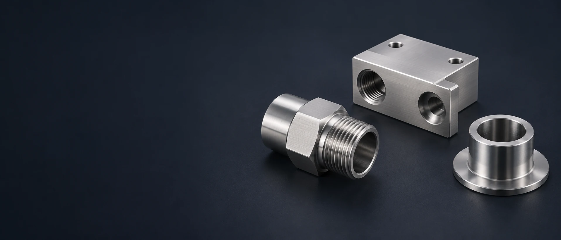
We turn connector bores, threaded ends, shoulders and wrenching details. The flow opening, attachment thread and sealing feature follow the released component drawing.
Valve-body blocks combine passages with port faces, internal seats and mounting details. We machine the body features and the specified access for removing burrs at connected holes.
We mill instrument cavities, cover seats and attachment points in 316 or 316L housings. The cavity clearance and sealing rim remain distinct from the internal mounting features.
A flanged sleeve combines an open bore, locating diameter and axial seating face. We machine those interfaces with the specified flange holes and entry edges.
We turn journals, shoulders and coupling details, then add specified flats, slots or cross-features. Shaft alignment and the surface that contacts a seal are controlled as separate drawing features.
We mill mounting faces, slots and fastening patterns for equipment brackets. Contact lands and accessible cleaning surfaces follow the drawing rather than being blended into a general cosmetic finish.
We supply these as drawing-defined machined components in the specified 316 or 316L condition, with the agreed finish and inspection scope.
316 contains molybdenum for improved pitting and crevice-corrosion resistance compared with common chromium-nickel grades such as 304. The actual fluid, temperature and crevice geometry still determine suitability; the alloy number alone does not approve an exposure.[1]
The lower carbon limit in 316L reduces the risk of sensitization and intergranular corrosion after welding. That is a material choice for the fabrication route, not a substitute for preparing the weld region or selecting a suitable service environment. [1] [2]
A supplied product can be certified to both 316 and 316L when it meets the applicable requirements of both. We keep that identity tied to the actual material record and product specification, rather than treating every 316L blank as dual certified. [2]
The table below concerns annealed flat products. A bar, hollow product or cold-worked blank has its own specification and property basis. We use the ordered stock condition for the cutting plan instead of applying the same strength figures to every 316 component.
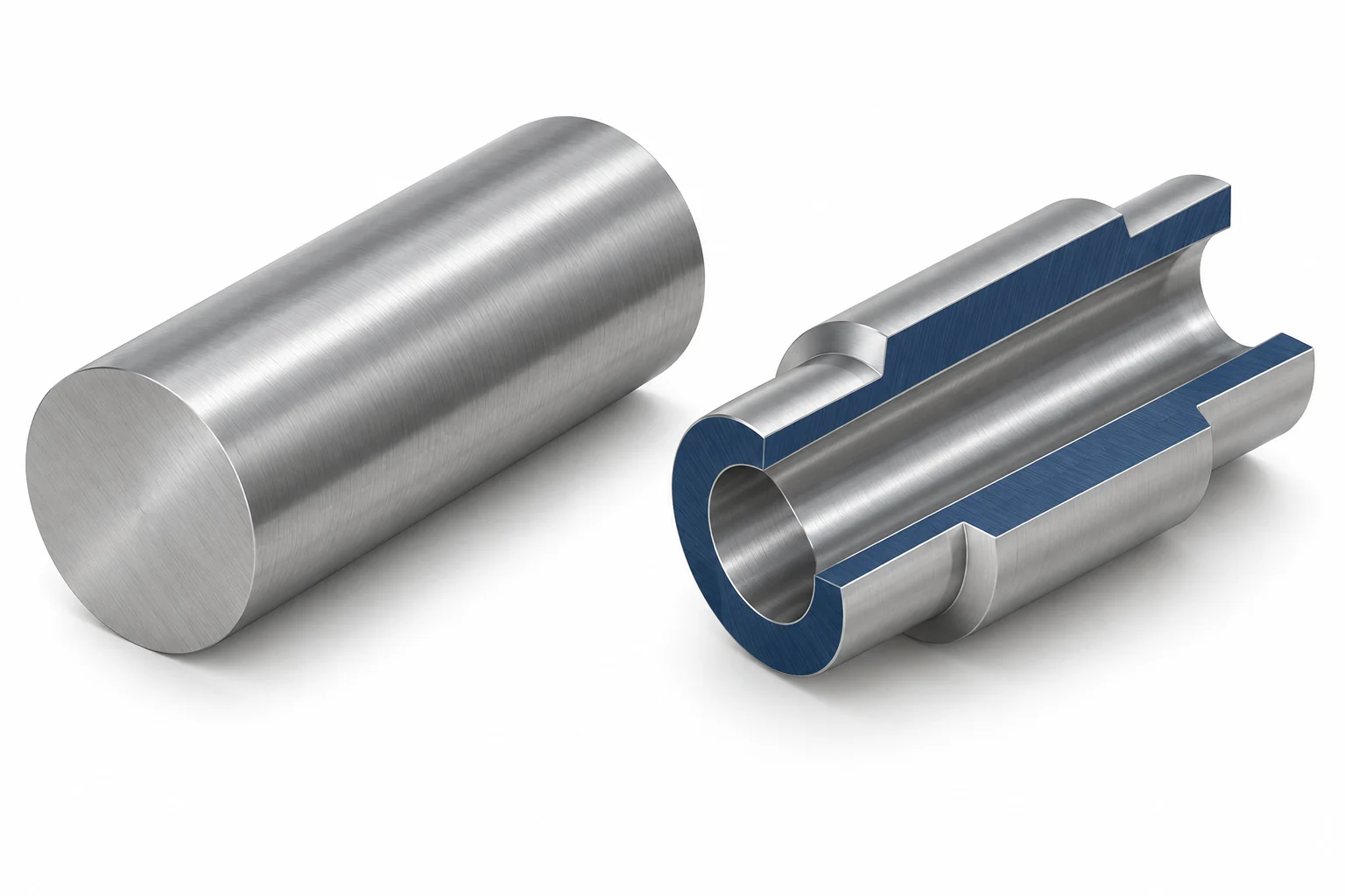
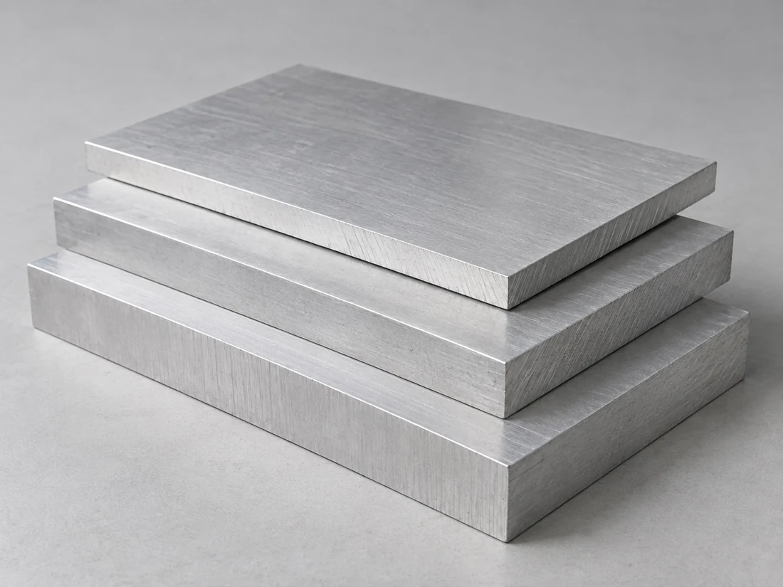
A minimum is an acceptance limit for the named material product, rather than its typical measured strength. A test result above that minimum can satisfy the ordered specification; it does not change the grade or replace the finished component’s drawing requirements. [1] [2]
The 316 and 316L columns retain their separate strength minima and common stated product form.
| Property | 316 / S31600 | 316L / S31603 | Basis |
|---|---|---|---|
| Carbon (% by mass) | ≤0.08 | ≤0.03 | Composition maximum |
| Molybdenum (% by mass) | 2.0–3.0 | 2.0–3.0 | Composition range |
| Chromium (% by mass) | 16.0–18.0 | 16.0–18.0 | Composition range |
| Tensile strength (MPa) | ≥515 | ≥485 | Material minimum |
| 0.2% offset yield strength (MPa) | ≥205 | ≥170 | Material minimum |
| Elongation (%) | ≥40 | ≥40 | 2 in / 51 mm gauge length |
| Brinell hardness (HB) | ≤217 | ≤217 | Material maximum |
Sources: ATI 316/316L/317/317L Technical Data Sheet (2012), annealed plate, sheet and strip under its stated ASTM A240 / ASME SA-240 basis; United Performance Metals lists the same selected 316/316L values. These references preserve the product and condition basis. The current governing specification for the ordered product sets acceptance; bar and cold-worked products have separate requirements.
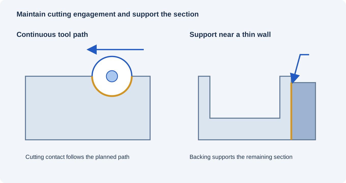
Austenitic stainless can work-harden during cutting. We plan the cut and tool engagement to remove material rather than repeatedly rub an already worked surface. The stock condition and the interrupted features influence that plan.
A connector or body can combine a deep bore, threaded port and intersecting hole. We plan tool access and chip removal for the complete connection, including the internal edges reached by the later operation.
A housing wall or long sleeve can deflect under cutting and clamping. Supported roughing and final passes preserve the important rim, bore or mounting face without using fixture force to stand in for the released geometry. [3]
Each interface is checked against the drawing in the specified final surface condition.
| Feature | Requirement or reference | Accepted condition | Verification |
|---|---|---|---|
| Selected locating bore | Ø20 H7: 20.000–20.021 mm | Where selected by drawing, after the specified finish | Finished bore measurement |
| Sealing land | Drawing geometry, local roughness and edge limits | Specified delivered surface | Size, geometry and roughness checks |
| Connected internal holes | Connection geometry, edge and cleanliness requirements | After final deburring and cleaning | Agreed internal inspection and cleanliness method |
| Welded or polished interface | Final drawing dimensions and processed areas | After the included operations affecting that interface | Applicable dimensional and surface checks |
The Ø20 H7 limits are a selected ISO 286 reference, not a default fit for every 316 part. Seal performance, internal cleanliness and application testing retain their own acceptance basis.
A bright or passivated component still needs its dimensional checks. Cleanliness and the surface-treatment result are reported against their own acceptance basis.
A dry exterior bracket and a continuously wetted passage can face very different conditions. Chlorides, temperature, deposits and the fluid chemistry affect localized corrosion; the required grade is selected for that exposure rather than a broad “marine” label.
Tight gaps under a seal, trapped fluid at a threaded joint and undrained recesses can create more severe local conditions than an exposed face. The released design determines the contact gap and drainage; machining preserves the intended access and geometry.
Stainless contact pairs can gall under load and motion. Thread engagement, surface condition, the mating material and any permitted lubrication are assembly choices; a corrosion-resistant alloy is not automatically a low-friction bearing material. [3]
A later weld or permanently closed joint can make an internal surface difficult to clean or inspect. We keep the specified machining and finishing stages aligned with that access, especially around a sealing land or connected passage.
A connection needs the right relationship between the flow opening, seal feature and attachment. That geometry lets the selected seal and mating part engage as designed; it is more specific than matching a nominal pipe or port size.
The cover rim closes around the installed instrument while the bosses support it. Their heights, clearances and fastening access determine whether the housing can be assembled and reopened without loading the instrument against the cavity wall.
A seal track, supporting journal and coupling seat have different contact duties. Their position and surface condition follow the mating seal or bearing requirements, and wear life is assessed against those contact duties.
A mounting bracket carries the attached item through its working lands and fastening pattern. Accessible corners and the spacing around the mount can also help the installed assembly drain and be cleaned without changing the load-bearing contact faces.
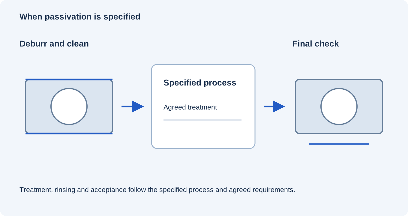
We remove the specified burrs and machining residues from accessible surfaces and internal connections. Cleaning and any required descaling precede the selected chemical treatment; chips and lubricant are not left for passivation to resolve.
Passivation addresses surface contamination such as free iron and supports stainless steel’s passive surface. It is not a deposited protective layer. The agreed process and acceptance check follow the component’s grade and surface condition.
A sealing face, sliding land and visible exterior may need different finishes. We keep their drawing-defined roughness, polishing areas and edge limits distinct so an appearance operation does not remove a functional feature.
The cleaned part is kept separate from sources of recontamination and protected for the agreed delivery condition. Internal openings and contact faces follow the specified handling and packaging requirements.
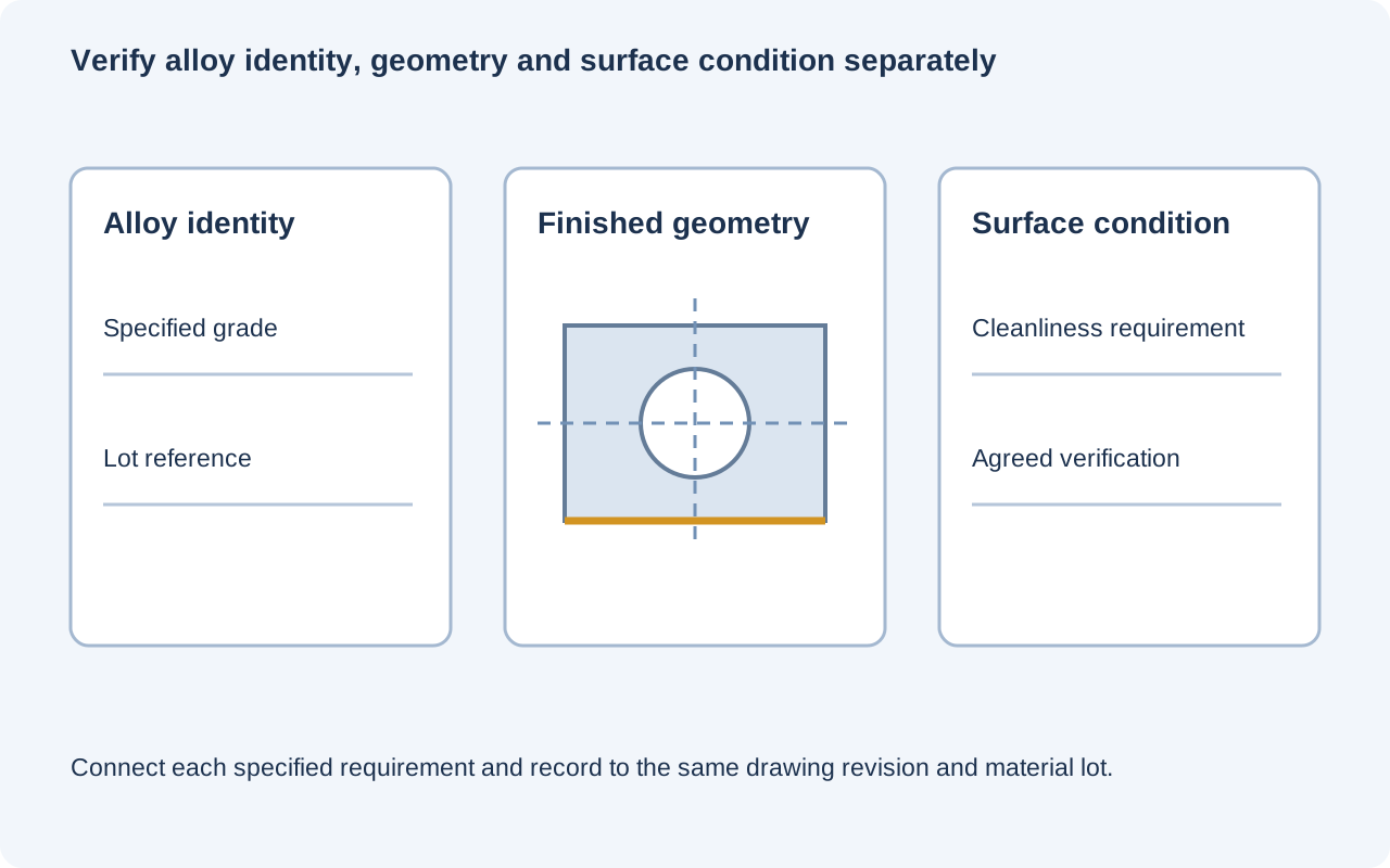
The required material record identifies the alloy, product form and supply condition, including dual certification where applicable. We retain its link to the component batch and approved drawing revision.
We check the specified bores, faces and datum relationships in their final accepted state. The measurement plan distinguishes dimensions, local roughness and internal edge acceptance rather than recording only an overall outside size.
A passivation or cleanliness requirement has its own acceptance method and record. Pressure, leak, hygienic or other application qualification is a separate specified scope; it is not inferred from the alloy certificate or a machined component’s appearance.
The ordered grade and stock condition affect material selection and cutting work. A round blank near a sleeve’s envelope and a plate cut down to a bracket leave different amounts of unused stock.
Deep connections, interrupted cuts and slender sections can add tool changes, support and chip-removal work. An inaccessible internal edge can cost more to finish and verify than a similar visible edge.
Specified polishing, cleaning, passivation and their acceptance checks add distinct operations. Required internal access and the number of separately controlled surfaces affect that work, rather than the finish being priced only by the part’s weight.
Programming, setup and initial fixture preparation are spread over the parts made together. Repeating the same approved stock and surface route can reuse that preparation; a changed grade or acceptance condition can require a new plan.
A fit sample can establish installation access, cover closure or engagement with a mating fitting. That trial is kept distinct from the final fluid exposure and any surface or application test required for production.
The production reference uses the intended grade, stock condition and finished surfaces. Approval includes the specified sealing lands, internal edges and contact features instead of relying only on external appearance.
The batch follows the accepted drawing revision, material definition and finishing scope. Changes to a passage, seal interface or treatment requirement are resolved before the remaining parts are produced.
A new cleaning chemical, temperature or mating material can change the suitability of an otherwise unchanged 316 part. An unchanged repeat follows the approved component and delivery definition.
Not if the released requirement also calls for the 316 strength level. Dual certification means the actual product meets the applicable requirements of both designations. The material record and governing product specification are what support a 316 callout, through dual certification to both designations.
No. The lower carbon primarily addresses sensitization and intergranular corrosion after welding. The pitting and crevice-corrosion choice still depends on alloy composition, surface condition and the actual exposure. Selecting 316L does not remove a chloride or crevice limitation simply because the carbon limit is lower.
It is not an anti-galling treatment. Passivation does not provide a lubricating layer or resolve the contact mechanics of the thread pair. Mating materials, surface condition, engagement and any allowed lubricant remain part of the assembly design, even when both components meet their corrosion-treatment requirement.
No. These austenitic grades do not gain hardness through the conventional quench-and-temper route used for suitable alloy steels. Cold working can increase strength and hardness, but it also changes the supplied material condition. A required wear or strength property needs a suitable material and process choice rather than an assumed hardening step.
Not automatically. Weld oxides and scale need the specified cleaning or descaling preparation; passivation is not a substitute for that work. A component welded after machining therefore needs an appropriate final surface route for the weld and adjacent area, including access to the surfaces that matter.
No. ATI identifies strongly reducing acids such as hydrochloric acid as potentially harmful to these stainless grades. The cleaner’s chemistry, concentration, temperature and contact time must suit the component and its service route. The cleaning stage is an exposure to assess, even when the normal operating fluid is acceptable.
Share the component drawing, material specification and quantity. Include the required surface condition and any fluid or cleaning exposure that affects the part; we will quote the agreed machining and finishing scope.
Grade, product-condition and surface-process references for the distinctions above.
We use Google Analytics to see how this site is used. Analytics cookies are set only if you accept. Privacy Policy
