Threaded sensor housings
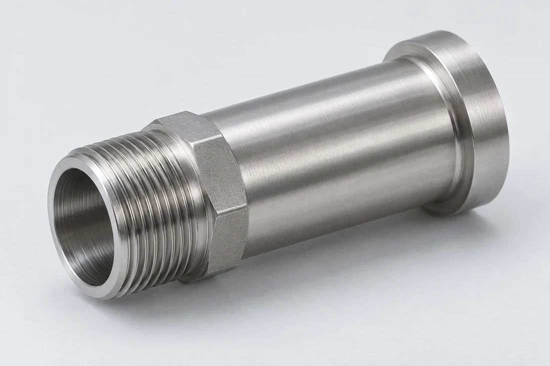
We turn hollow bodies with the specified external mounting thread, internal bore and assembly shoulder. The bore depth leaves the space required for the sensing cartridge and its rear connection.
Discuss this component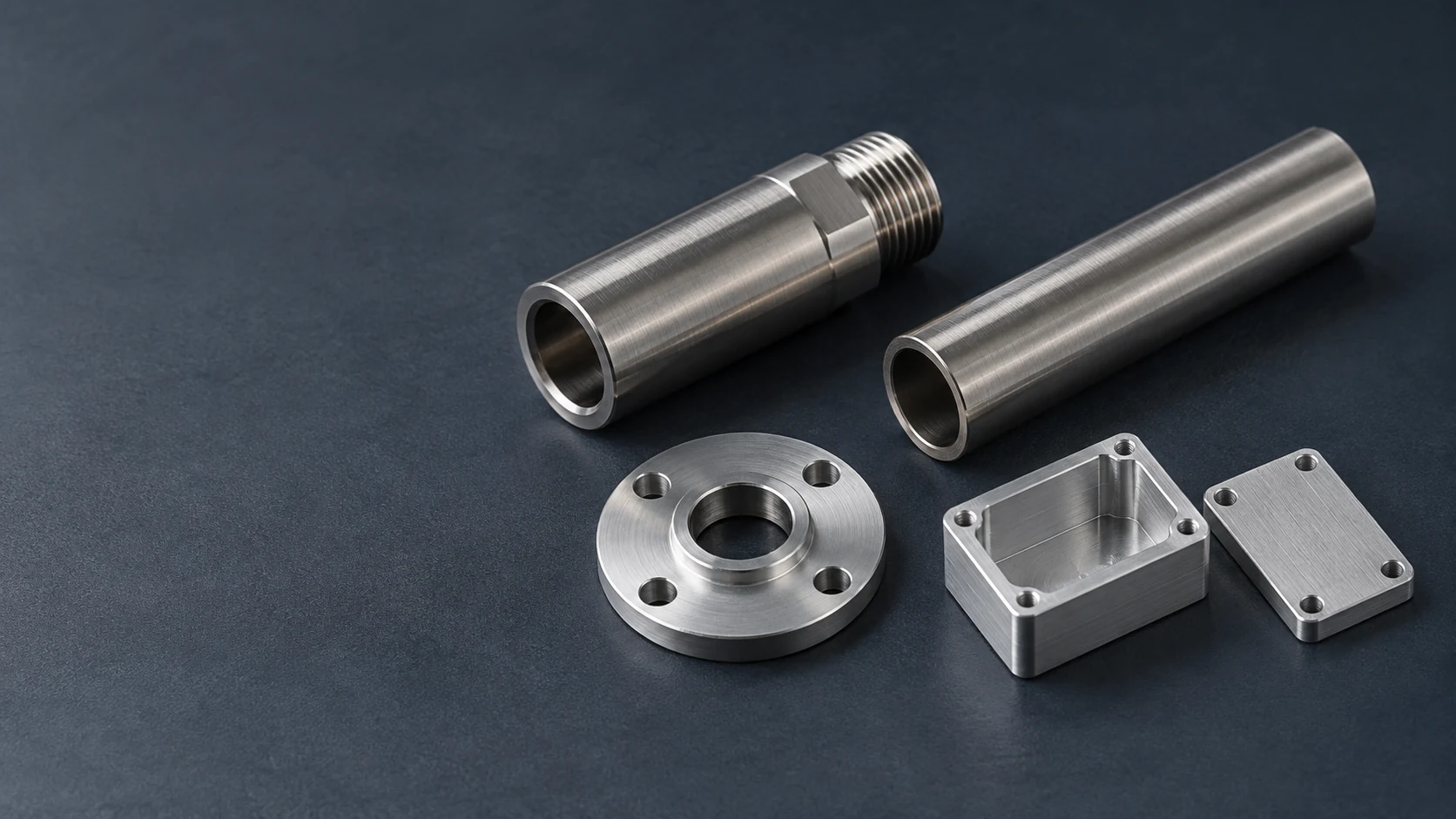
We machine empty sensor housings, probe holders, cable-entry adapters and mounting parts for sensor manufacturers and equipment builders. Our work connects the sensing assembly to its housing and installation point through the bores, shoulders, threads and sealing surfaces defined in your drawings.
We manufacture the mechanical parts around the sensing assembly: its outer body, internal support and connection to the equipment. The component drawing defines what is inside, what mates outside and which surfaces must remain accessible.
We turn hollow bodies with the specified external mounting thread, internal bore and assembly shoulder. The bore depth leaves the space required for the sensing cartridge and its rear connection.
Discuss this component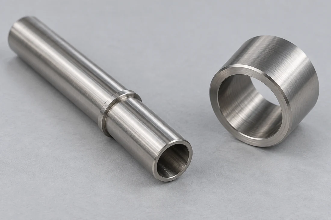
Stepped sleeves support a probe at the defined diameter and insertion stop. The seating shoulder and bore share a reference axis so the installed probe position follows the component drawing.
Discuss this component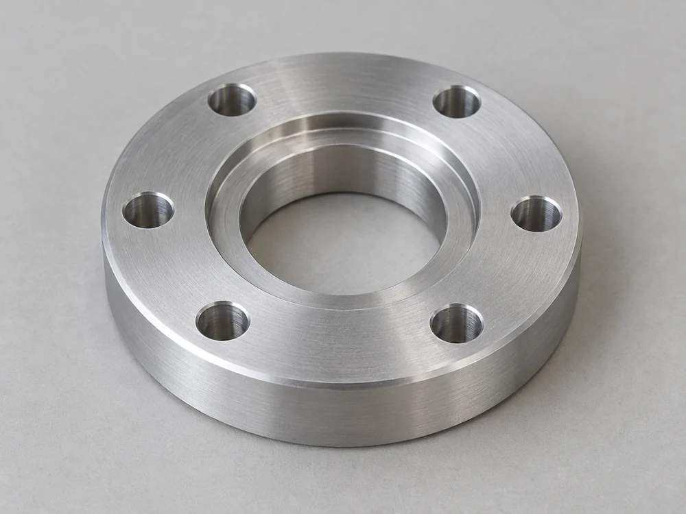
We machine flange patterns, pilots and connection features that join the probe holder to the equipment. A process connection also needs its specified sealing geometry; the mounting pattern alone does not define that joint.
Discuss this component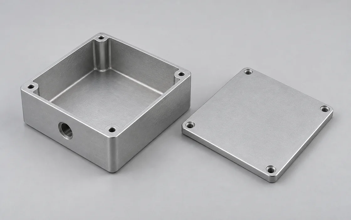
Milled bodies provide the cavity, cover ledge and attachment points for the sensor assembly. Side openings are located from those internal references so the installed connectors align with the enclosure.
Discuss this component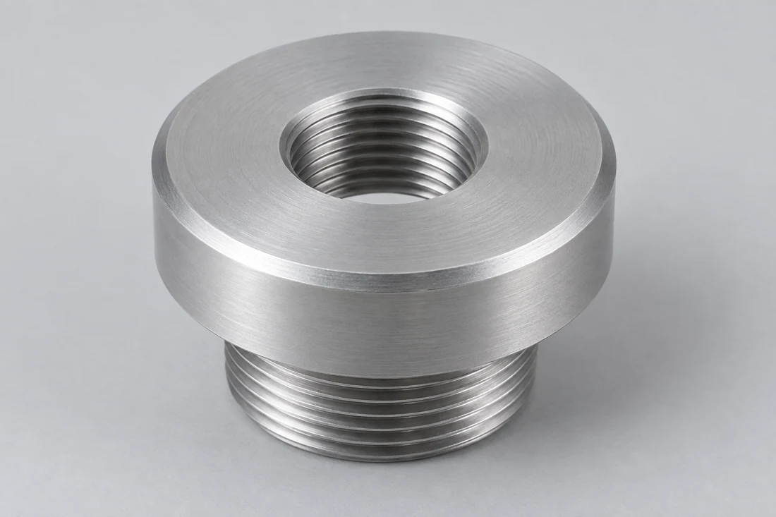
Turned endcaps and entry adapters connect the housing to the selected gland or connector. We machine the specified thread or clearance opening together with its seating face and tool-access features.
Discuss this component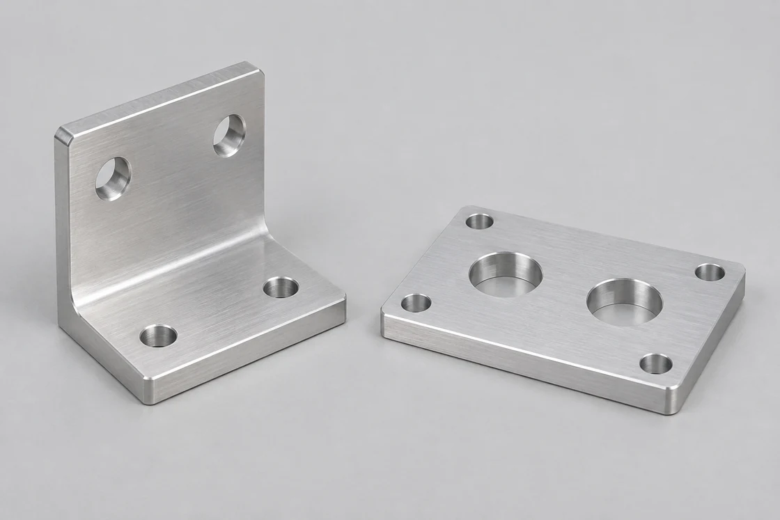
Brackets and mounting plates establish the sensor location on a machine. Fixed bores or adjustment slots follow the intended setting method, with space for the retaining nuts and rear connector.
Discuss this componentThese applications use different reference features. A housing locates the internal assembly, a holder sets the probe depth, and a machine bracket establishes the installed sensor position.
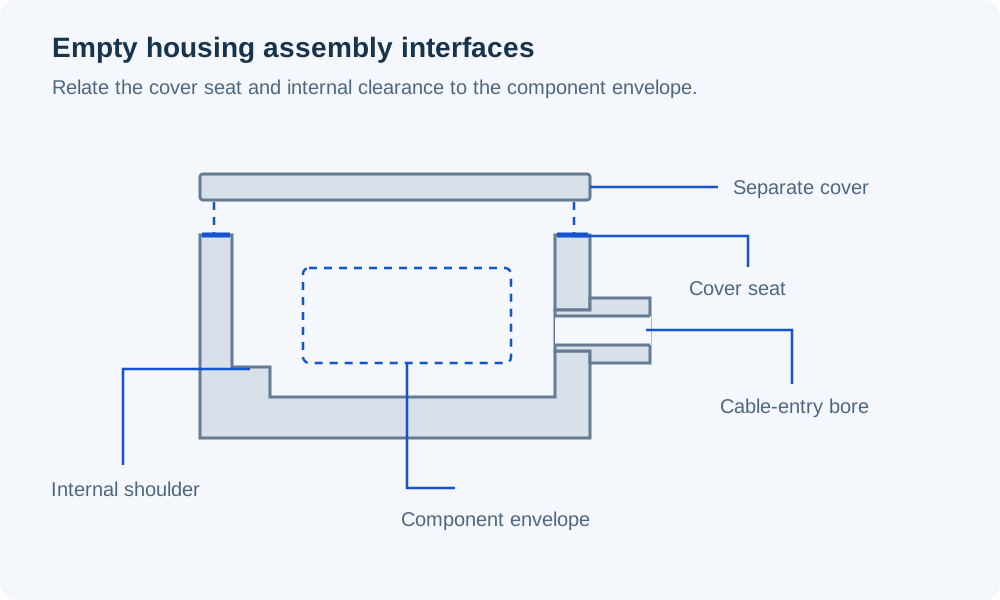
We machine the cavity from the assembly envelope and its chosen locating surfaces. The cartridge may seat on an internal shoulder while a separate cover retains it; the drawing identifies which surface sets its axial position.
Rear openings follow the connector position in that seated assembly. A connector that fits through the wall still needs room for its retaining hardware and the adjoining cable.
The component envelope includes the required assembly clearance, with contact restricted to the designated support surfaces.
The cover ledge, screw pattern and closure depth belong to the same assembly definition as the internal shoulder.
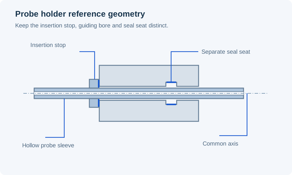
We machine the holder from the probe support diameter and the stop that sets its insertion. Overall sleeve length is useful only when its relationship to the equipment mounting face is also defined.
At a process connection, thread engagement and sealing are separate requirements. WIKA’s connection guidance distinguishes parallel-thread face seals from tapered-thread sealing; the selected connection drawing determines the required seat.
The working depth starts from the specified mounting or seating face, not an arbitrary outside edge of the holder.
The seal contact, groove or seat remains a controlled feature alongside the mounting thread.
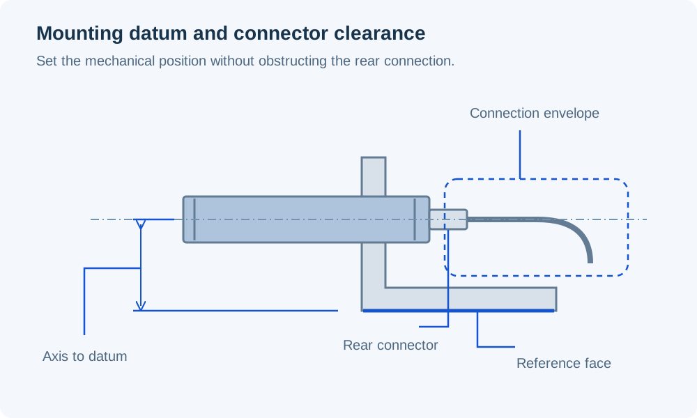
We machine the bracket bore or device pattern relative to the machine-side mounting face. That relationship establishes the mechanical position before the equipment team sets the sensor’s operating gap or target.
Adjustment features must leave room to secure the final position. The installed connector and its coupling nut need access after the bracket is fixed to the machine.
The mounting face and hole pattern define where the sensor axis sits in the equipment assembly.
The slot direction, retaining hardware and tightening path are considered together in the bracket geometry.
Different development deliveries answer different questions. We retain the part revision associated with each housing, holder and installation interface.
Initial housings and sleeves establish whether the cartridge seats, the cover closes and the selected connectors can be installed in the available envelope.
The specified material and surface condition support the sensor team’s assembly and application evaluation. Changes to insertion stops, cavity depth or connection geometry remain identifiable by revision.
Repeat components follow the accepted mechanical definition. A changed cartridge, gland or probe connection is carried into the affected part drawing before it becomes a replacement order.
Housing mass and the relative movement of adjoining parts affect the material choice. The references below distinguish metal bodies from polymer supports; the selected grade must also suit the actual medium and cleaning conditions.
| Material / condition | Reference parameters | Component context |
|---|---|---|
| 6061-T6 / T6511 extrusion | Yield ≥240 MPa; density ≈2.71 g/cm³ | Lightweight housing bodies and mounting parts |
| 316L / EN 1.4404 | Elastic modulus 200 GPa at 20°C; CLTE 16 µm/(m·K), 20–100°C | Specified stainless bodies and probe supports |
| Unfilled POM-C · TECAFORM AH natural | Tensile modulus 2.8 GPa; CLTE 130 µm/(m·K) | Internal support sleeves and locating inserts |
| Unfilled PEEK · TECAPEEK natural | Tensile modulus 4.2 GPa; CLTE 50 µm/(m·K) | Specified polymer supports with lower reference expansion than POM-C |
References: Hydro Alloy 6061 extrusion minimum yield and typical density; Outokumpu Supra 316L/4404 physical data; Ensinger European metric data for the named stock grades. Polymer modulus: 1 mm/min; polymer CLTE: longitudinal, 23–60°C. CLTE is linear thermal expansion. These material references do not establish assembled-sensor performance.
We plan the operations around the surfaces that locate the sensing assembly and connect it to the equipment. Those references carry through any change of setup.
Milling creates cavities, cover ledges, mounting patterns and adjustment slots. Cavity supports and external mounting faces stay related to the assembly datums rather than being dimensioned as unrelated features.
CNC milling servicesTurning produces concentric bores, stepped diameters, body threads and axial seats. Thin sections need suitable support during machining so clamping does not define the finished shape.
CNC turning servicesA housing with side openings or angled mounting features may need indexed machining. Their location is referenced to the finished main bore or mounting face so the connector meets the intended internal position.
5-axis machining optionsWe separate the features that locate the assembly from those that retain or seal it. Each has its own dimensions and acceptance requirements on the component drawing.
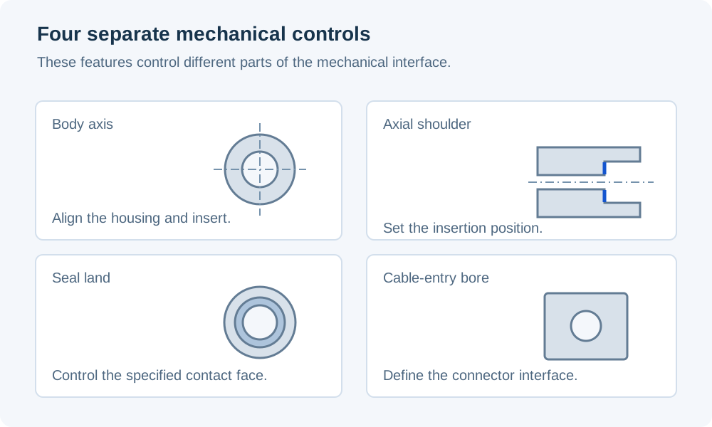
The internal support bore is related to the mounting pilot or body axis. Diameter controls the fit; position and orientation control where the installed probe or cartridge sits.
A shoulder needs a defined contact face and clearance for the mating corner radius. The intended part must reach that face before another edge or thread runout stops it.
We preserve the specified seal-contact width, groove geometry and surface texture. Burr removal must not round away a sealing edge or change the groove section.
A tapped port and a clearance hole with a locknut are different mounting details. The selected gland drawing determines the opening, wall thickness and seating face; its cable-clamping range does not define the housing bore.
The finish drawing separates the housing exterior from the interfaces used during assembly. We retain those distinctions when machining and preparing the parts for the specified treatment.
An anodized exterior can share a part with masked threads, bores or closure contacts. The treatment specification defines where coating is allowed and the dimensions required after finishing.
Seal lands and grooves retain their specified texture and edge condition. A cosmetic treatment is not extended across them simply to make the whole housing look uniform.
Internal passages and pockets need clear burr and residue requirements before the sensing assembly is installed. Any special cleaning, packaging or surface preparation is part of the quoted supply scope.
Similar thread labels can refer to different interfaces. These selected references distinguish a sensor body mount from a gland entry; the released component drawing supplies the final fits, depths and surface limits.
Inspection relates the internal seats to the mounting references. A thread check does not establish probe insertion depth or acceptance of an adjoining sealing face.
| Interface / feature | Reference dimensions | Component acceptance |
|---|---|---|
| Selected ifm sensor-body mounts | M12 × 1; M18 × 1 | Specified body diameter, pitch, thread fit and engagement |
| Metric cable-gland entry thread | M12 × 1.5; M20 × 1.5 | Selected gland interface; thread depth and seating face |
| M20 gland clearance-hole mounting | Ø20.0–20.2 mm | Non-threaded opening; selected gland and locknut arrangement |
| Probe insertion stop | Axial distance in mm; drawing limits | Depth from the defined equipment seating face |
| Seal-contact face or groove | Dimensions in mm; texture in µm; drawing limits | Seal geometry, texture and damage condition |
References: ifm IFT259/IFT260 and IGT261/IGT262 body threads; LAPP metric gland thread and borehole table, EN 60423 / IEC 62444. The Ø20.0–20.2 mm value is a clearance bore, not an internal-thread minor diameter. The selected hardware and component drawings control final acceptance; no common probe-depth or seal-finish limit is implied.
We quote machined components and the specified dimensional inspection. Sensor electronics, calibration, completed-device ingress or pressure testing, and hazardous-area qualification are separate from this component supply.
Threads, internal seats and thin sleeve walls need protection through handling. Component identification keeps externally similar housings tied to the correct internal configuration.
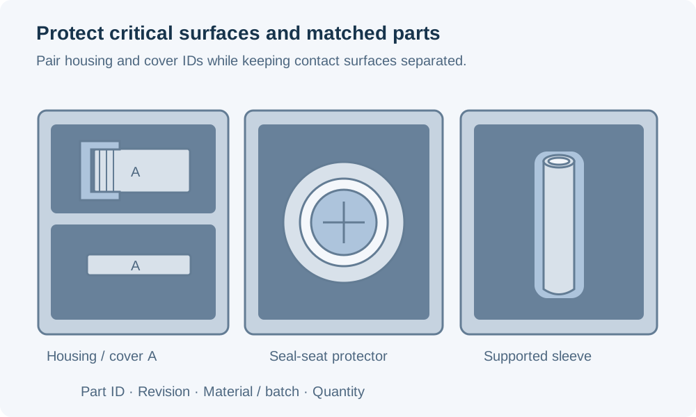
We identify the part number and revision for the housing and each related closure. A cover with a similar outside outline can still have a different seating depth or connector opening.
Thread form, entry size and probe-stop variants retain separate component references. This prevents a visually similar alternative from entering the wrong sensor assembly.
Packing separates thin sleeves from heavier bodies and protects exposed threads and seal-contact surfaces from contact damage. Temporary protection remains distinguishable from supplied assembly hardware.
Only if the selected sensor permits that installation. The required surrounding clearance can differ even when both bodies have the same thread. Use the exact model’s installation drawing to define the bracket opening and nearby metal; a successful thread fit does not establish the permitted sensing-face arrangement.
A thread alone does not establish a repeatable angular position. If the connector must face a particular direction, the assembly needs a defined clocking method, such as a separate locating feature or independently oriented connector mount. We machine that chosen geometry; we do not infer its orientation from the thread size.
The cavity drawing needs to distinguish the filled volume, fill or vent access, and areas that must stay clear for connectors or service. Identify the surfaces intended to bond before specifying an internal coating. We supply the machined cavity; compound selection, adhesion and curing validation belong to the sensor assembly process.
An open sleeve locates the probe while leaving its end exposed. A closed end adds a barrier between the probe and its surroundings, which changes the assembly and may affect response. Use the sensor designer’s approved geometry; a closed sleeve is not automatically a pressure-qualified thermowell.
Only if the connector and its installation hardware can pass through the opening in the required assembly sequence. Cable diameter alone is not enough. Where passage is impossible, the design may need assembly before termination or a separately defined split or removable closure.
A sensing diaphragm is a functional element with its own geometry, material and joining requirements. It is not included in an empty housing order. Our component quotation identifies the housing and mounting parts supplied; diaphragm manufacture, joining and sensor calibration require a separate qualified scope.
Reserve a marking area on the drawing outside the seal contacts, fitting threads and thin functional sections. State whether the mark must remain visible after the sensor is installed. That lets identification survive assembly without placing a recess or surface change on an interface used by the sensor design.
Equipment examples retain their named-product scope; material values retain their grade and test conditions.
Send the model, component drawing, material and quantity. Include the mating cartridge, probe, connector or gland drawing where it defines the machined interface.
