On this page
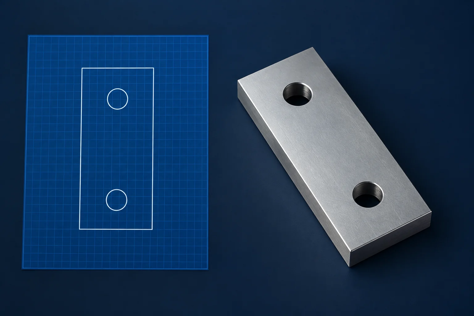
For a conventional CNC machining handoff, send the 3D model for geometry and a matching 2D drawing for the requirements that the model does not contain. A plain solid model can show a bore, pocket or curved surface without specifying its acceptable variation, material or finished condition. A drawing can supply those requirements through dimensions, notes and referenced specifications.
Neither file type is mandatory in every workflow. A sufficiently detailed drawing may define a simple part on its own. An agreed model-based definition can carry manufacturing information in the model and associated data instead. The useful question is whether the recipient has a complete, consistent definition of the part—not whether the package contains two file extensions.
What each file needs to communicate
A 3D model makes the spatial relationships between features accessible without reconstructing them from separate views. A technical drawing presents selected views, dimensions and instructions in a readable document. Section views can expose internal features; detail views can clarify a small area. [1]
| Information | Plain geometry model | Where to define the requirement |
|---|---|---|
| Nominal shape | Surfaces, holes and feature locations | Model geometry or a sufficiently defined drawing |
| Acceptable variation | Shape alone does not establish limits | Dimensions, GD&T and applicable general requirements |
| Thread specification | A hole or cosmetic thread may be present | Thread designation, class and required length/depth |
| Material and condition | Appearance does not identify the required stock | Material specification and delivery condition |
| Surface requirements | Color and shading are not acceptance criteria | Texture, treatment and affected surfaces |
These requirements can also appear in model annotations and associated specifications. Geometric dimensioning and tolerancing (GD&T) applies to both engineering drawings and digital models; ASME Y14.5 describes the corresponding language. Use the convention and edition required by the project. [2]
A bore diameter does not define the whole interface
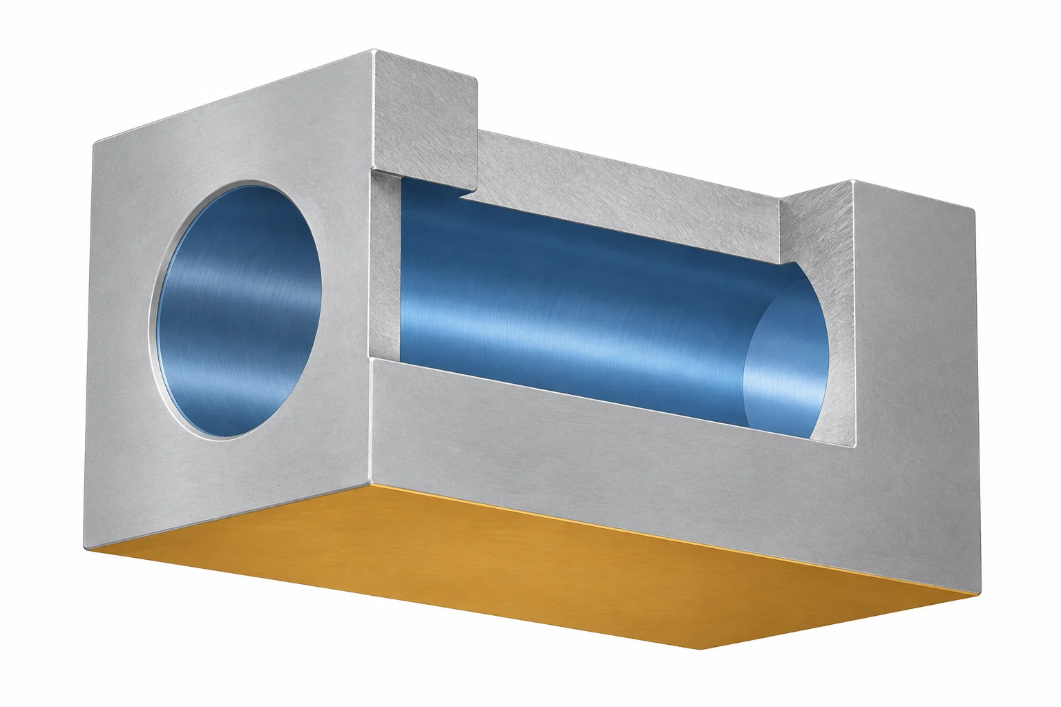
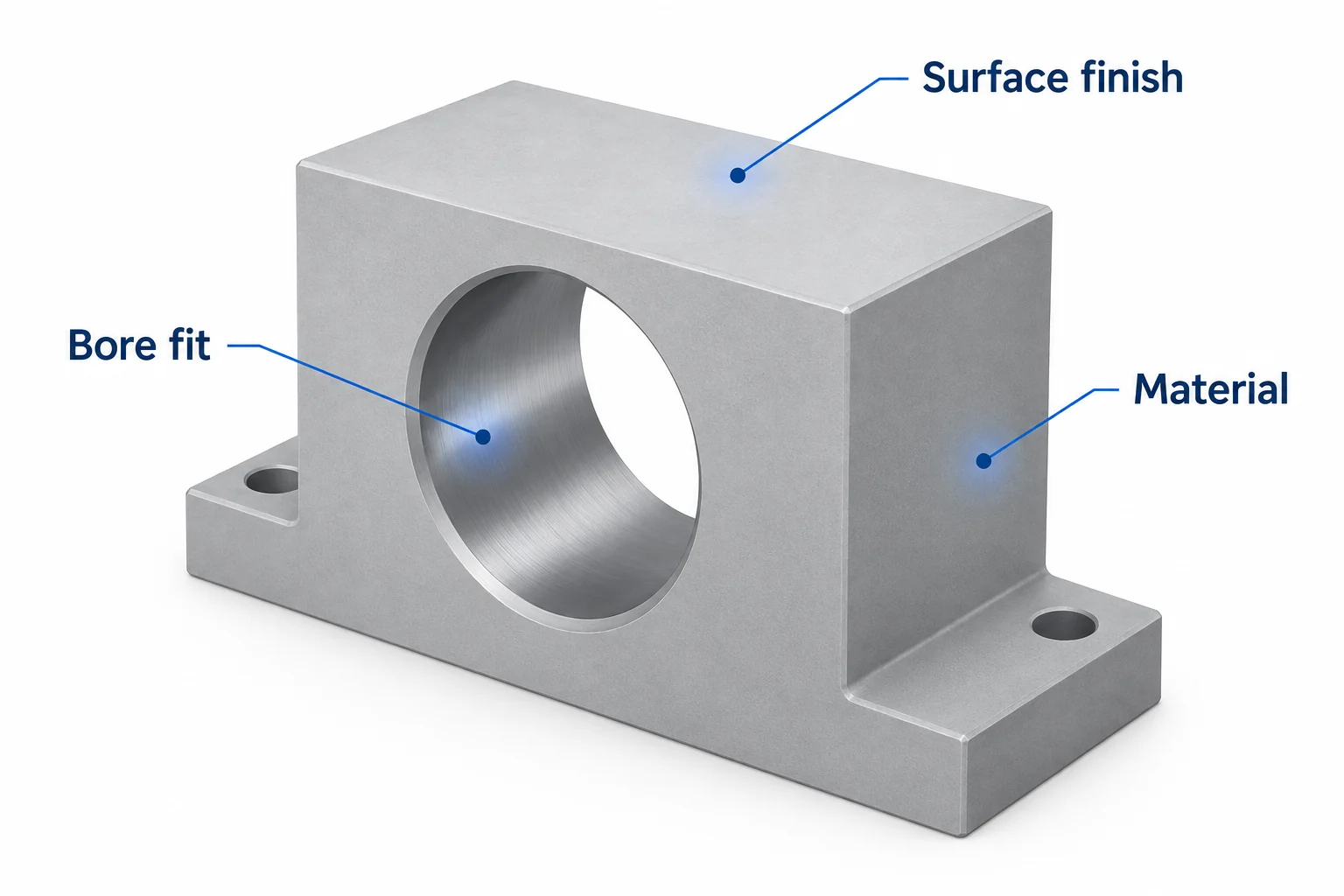
Consider a bearing block with a horizontal bore and a flat mounting face. Measuring the bore in the CAD model gives its nominal diameter. That measurement does not, by itself, establish the limits needed for the bearing fit or the bore’s permitted relationship to the mounting face.
The designer must define the functional requirements: the bore size limits, any necessary geometric controls and datum references, and the relevant surface texture. The material and any treatment belong in the same released definition. A smooth-looking CAD surface does not specify a roughness value, and a silver rendering does not distinguish aluminum from steel.
Before calling a dimension “untoleranced,” read the complete definition. A title-block tolerance, general note or expressly referenced specification may already apply. If no applicable requirement resolves the question, obtain clarification rather than assigning an arbitrary tolerance. The CNC machining basics guide explains the distinction between size, geometric requirements and surface texture.
Choose the package for the part and the workflow
A complete 2D drawing can be enough for straightforward geometry. A spacer or simple turned sleeve may be fully described by its views, dimensions and notes. Confirm how the shop will program it and whether it needs to reconstruct a model. A missing 3D file does not automatically make such a part unmanufacturable.
A model is especially useful for complex surfaces and spatial features. A small collection of dimensions cannot fully describe an arbitrary sculpted surface. Supplying its digital geometry avoids asking the recipient to infer that surface from a picture. The remaining manufacturing and acceptance requirements still need an agreed home.
A geometry-only model may support an initial discussion. If fit limits, material or finish remain undecided, identify those open items. Any estimate needs clear assumptions; it is not a complete production release. For quantities, inspection records and purchasing scope, use the CNC machining RFQ guide.
When a model can replace the drawing
Model-based definition (MBD) combines the model with the information needed to define the product. Product and manufacturing information (PMI) can connect dimensions, tolerances and notes to the affected geometry. ASME Y14.41 addresses digital product-definition practices; simply sending an unannotated solid is not the same workflow. [3]
The receiving workflow matters. Graphical PMI shows annotations for people to read; semantic PMI encodes information for software to interpret. Seeing a tolerance on screen does not prove that another application can reuse it automatically. NIST distinguishes these forms and checks geometry and PMI in exchanged files. [4]
Before omitting the drawing, agree which model and associated documents are authoritative, which information the supplier needs, and how manufacturing and inspection will access it. Open and verify the delivered export, not just the native CAD file. An export that preserves the shape but loses required annotations leaves an incomplete handoff.
Resolve differences before releasing the files
A matching filename is useful identification, but it does not prove that the model and drawing agree. Check the files the supplier will actually receive:
- Identity: part number, revision and release status agree with the order.
- Geometry: units, overall shape and functional feature locations match the intended design.
- Requirements: local callouts, general notes, material and finish refer to the correct features and finished condition.
- Authority: the package identifies which data defines geometry and which defines other requirements.
Suppose the model places a locating hole in one position while the drawing places it elsewhere. Do not ask the shop to select whichever file looks newer. Have the responsible design owner resolve the difference, issue consistent files and identify the superseded release.
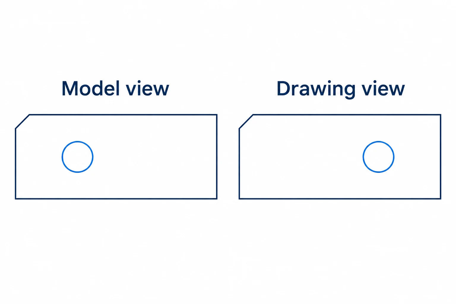
There is no useful blanket rule that the PDF always wins or that the 3D model always wins. Authority belongs to the agreed product definition. State it clearly, and correct known contradictions before production. NIST’s work on MBD verification emphasizes checking the master definition and its exported derivatives before downstream use. [3]
Where the preparation cost changes
Compare the work required to reach a usable definition. Starting with a paper drawing may require geometry reconstruction before CAM programming. Starting with a bare model may require additional dimensioning and clarification. Maintaining independently edited files creates another task: checking that a design change reached every affected document.
A reusable model-and-drawing set or an established MBD workflow can reduce repeated preparation, but only if its data stays consistent. NIST’s research shows that design, manufacturing and inspection need different information from the product definition. [5] Removing a document saves little if its required information must then be reconstructed.
For a repeat part, retain the approved files and a clear change record. For a revision, identify the changed features so programming and inspection can be reviewed. Ask whether a quote includes any necessary model reconstruction or drawing preparation. Neither “2D” nor “3D” alone establishes a fixed cost saving.
Questions about CNC models and drawings
Does a STEP file always contain tolerances?
No. STEP can carry PMI, but the actual content depends on what was authored and exported. Verify the received file and its associated requirements; the filename extension alone is not evidence of a complete definition.
Is a screenshot of the model enough?
A screenshot can help explain the part, but it does not provide reusable solid geometry or a complete controlled drawing. Use it as supporting context and provide the files and requirements needed for the agreed workflow.
Does adding a 2D drawing make a part more accurate?
The document does not improve machine performance. A clear, consistent definition communicates what must be made and accepted; the manufacturing and inspection processes must then meet those requirements.
Technical sources
- Dassault Systèmes, Technical Drawing for CNC Machining; views, drawing notes and feature callouts. Autodesk, Technical Drawing; model-derived drawings and revision information.
- ASME Y14.5: Dimensioning and Tolerancing; public scope description.
- NIST GCR 15-999: PMI modeling capability, Report 3, sections 1.1–1.3. ASME Y14.41, Digital Product Definition Data Practices; public scope description.
- NIST: STEP File Analyzer and Viewer; semantic and graphical PMI.
- NIST GCR 18-015, Extending and Evaluating the Model-Based Product Definition, pp. 2–3 and 34–35; information needs across manufacturing and inspection.



