On this page
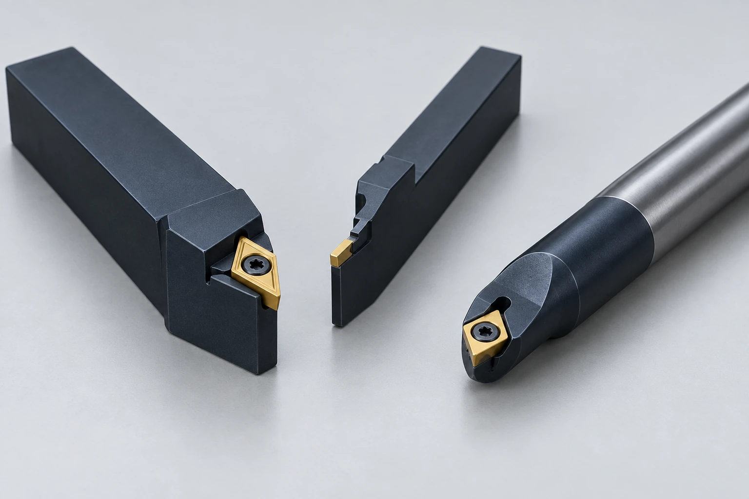
CNC turning tools combine a cutting edge with a holder that supports and positions it. For a turned part, the important question is whether that complete assembly can reach the surface, clear adjacent features and remain stable. An insert that fits the holder can still be unsuitable for the material or the cut.
Start with the feature being made. Our turning operations guide explains the cutting motions; this article looks at the tools that make those motions possible.
The insert and holder do different jobs
On an indexable turning tool, the replaceable insert provides the cutting edge. The holder supports it and establishes its orientation. The machine-side connection supports the assembly. These interfaces need compatible seats, clamps and dimensions; visual similarity is not sufficient.
Insert shape, nose radius, chipbreaker geometry and grade describe different choices. Shape affects access. The nose radius is the rounded tip, not the angle between its sides. Chipbreaker geometry must suit the feed and depth of cut, while grade selection depends on workpiece material and cutting conditions.
A pointed insert can reach more profiles
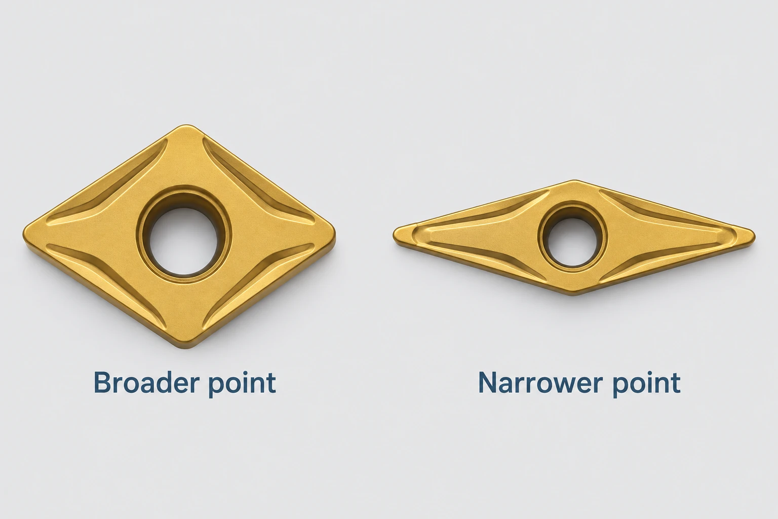
A narrower included point angle can provide clearance around a changing profile, at the expense of edge strength. A broader point is stronger but cannot enter every recess. The holder’s orientation also matters: selecting a slender insert alone does not establish clearance behind a shoulder.
Match the complete tool to the part feature
| Part feature | Tooling constraint | Useful drawing information |
|---|---|---|
| Shoulder beside a diameter | Insert tip and holder clearance | Fillet radius and mating-face requirement |
| Recessed groove | Blade reach and side clearance | Width, depth and root shape |
| Internal diameter | Bar size, overhang and chip space | Bore diameter, depth and entry geometry |
| Turned thread | Thread profile and tool exit space | Designation, full-thread length and runout allowance |
A nose radius also affects forces and the resulting surface. Making it larger can strengthen the edge, but can increase radial loading and vibration in a flexible setup. Making it smaller is not a universal finishing improvement. A functional shoulder radius should be specified from the mating geometry, with tooling access reviewed against it.
Threads require their own cutting profile. A full-profile threading insert forms the crest as well as the flanks and root, and is matched to the thread pitch and form. A partial V-profile insert can cover a specified pitch range but does not finish the crest; the relevant blank diameter must be prepared separately. Neither choice replaces thread inspection.
If the decision is between a turned thread and another method, see thread turning, tapping and thread milling. Insert selection comes after that process decision.
A boring bar needs space beyond the cutting edge
Internal turning adds a packaging problem. The insert must reach the cutting surface while the bar body clears the bore. A larger bar can improve stiffness, but it still needs room for the cutting edge, clearance and chip evacuation. The tool manufacturer’s minimum bore diameter applies to the specified assembly, not just the bar’s nominal diameter.
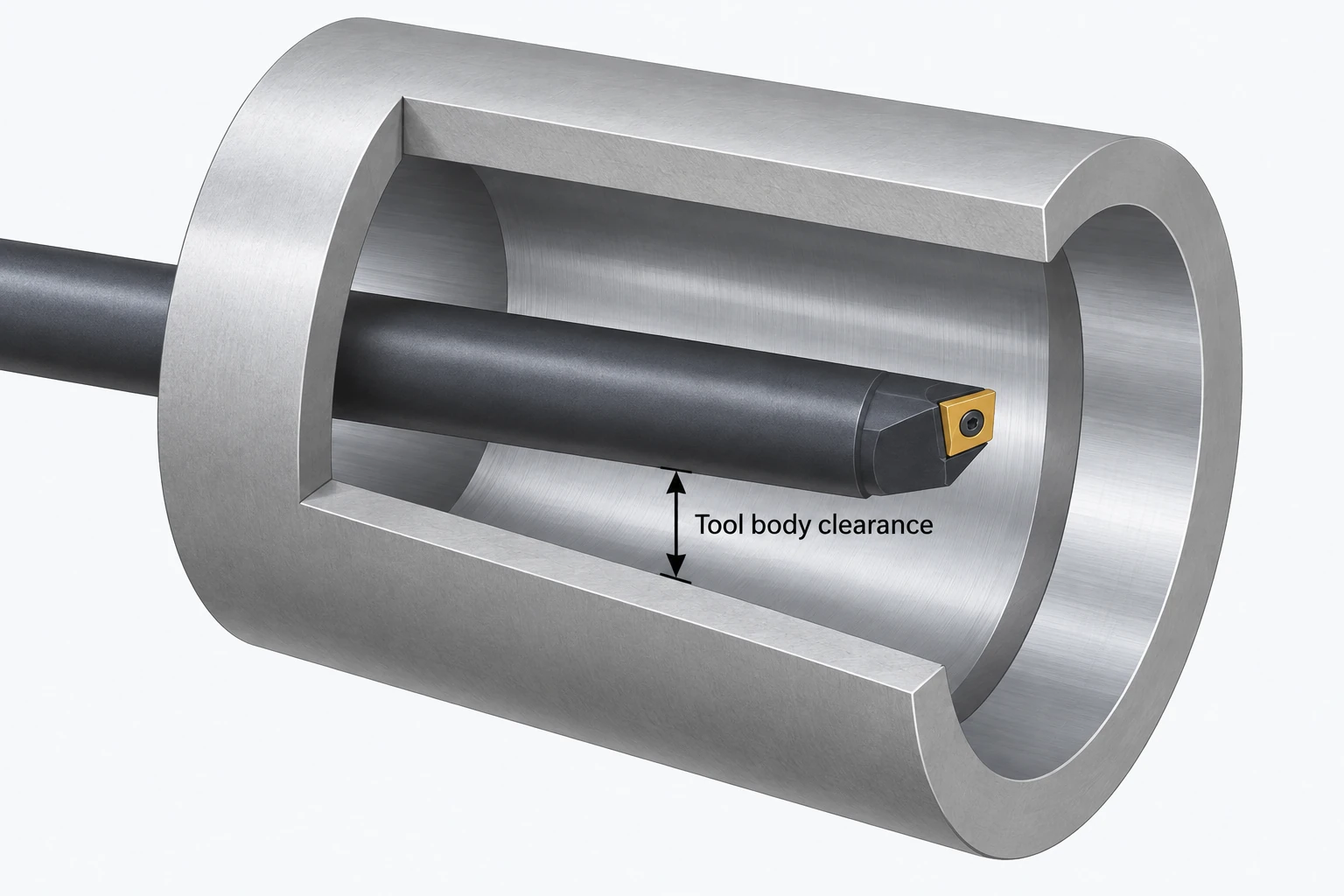
Reach is equally important. Unnecessary overhang increases the risk of deflection and vibration. A bar that enters the hole is therefore not automatically suitable for finishing its full depth. Blind ends, internal shoulders and restricted exits add access or chip-removal constraints that an outside diameter does not have.
For a CNC turning assessment, show the functional geometry and acceptance requirements. A section view through a deep bore or shoulder often communicates more than a proposed insert code. It lets the machining team assess an assembly and approach that preserve the required feature.
Frequently asked questions
Does a new insert automatically restore part size?
No. The replacement edge still has a position in the assembled tool. Seating, wear compensation, offsets and the resulting part need verification through the established setup and inspection process.
Can one turning insert machine every feature?
No. General turning, narrow grooves and threads have different edge and access requirements. Some tools cover several operations, but the actual profile and clearance determine what is possible.
Should a customer specify the insert brand?
Usually the drawing should define the part’s geometry, material condition, finish and acceptance criteria. Specify a tooling restriction when it is a genuine process requirement; otherwise, allow the machining team to select compatible tooling.
Technical references
Sandvik Coromant: How to choose correct turning insert; Internal turning; and How to choose thread turning insert and shim. These describe tooling principles and manufacturer recommendations, not VETCNC equipment or capacity.



