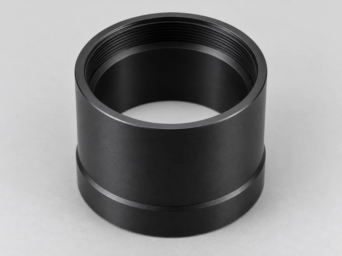
Lens barrels
Stepped internal bores, lens shoulders and retaining-ring threads in tubular bodies. External pilots, flats and side ports connect the barrel to its surrounding mount.
Discuss this barrel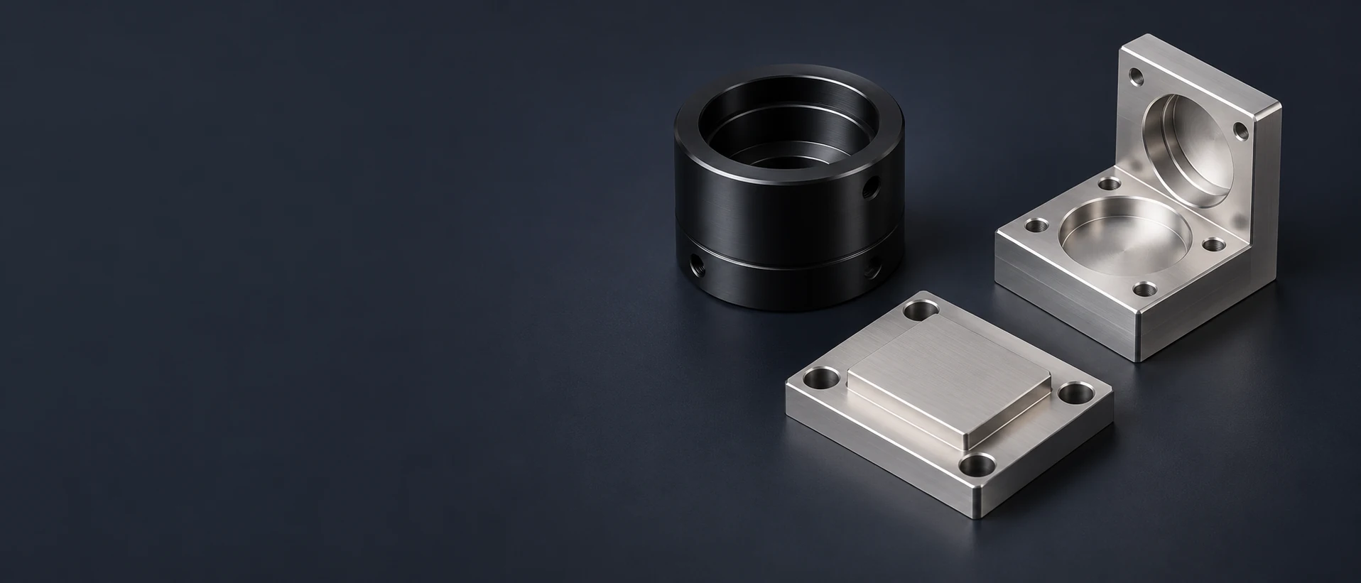
We machine optomechanical housings, lens barrels, mounts and baseplates for machine vision, laser instruments and spectroscopy. Our milling and turning service supplies the mechanical parts that locate and support the optical assembly.
Our custom component work covers cylindrical optical hardware and the milled structures around it. Barrels and rings can be ordered individually, or alongside housings, brackets and plates for the same instrument build.
Stepped internal bores, lens shoulders and retaining-ring threads in tubular bodies. External pilots, flats and side ports connect the barrel to its surrounding mount.
Discuss this barrel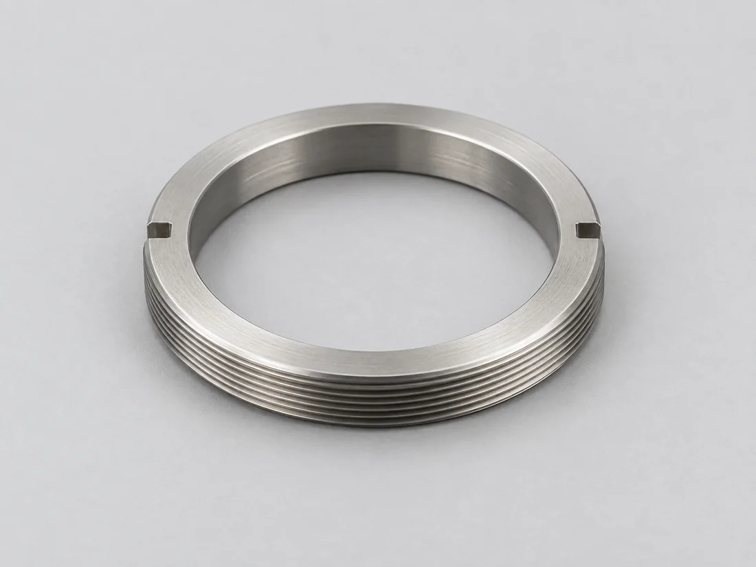
Turned rings provide axial retention or separation within an optical stack. Contact lands, clear openings and spanner slots are machined to the component drawing.
Discuss these rings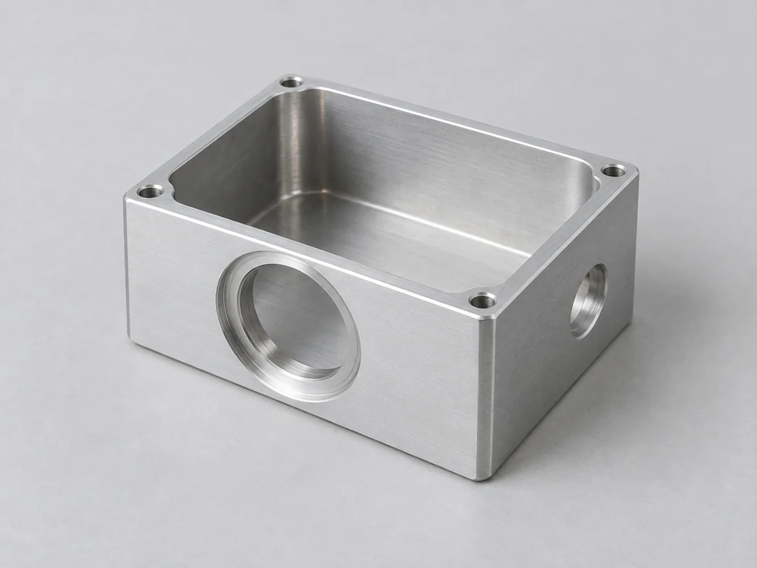
Milled enclosures combine detector-support bosses, internal pockets and cable or connector openings. Removable covers remain separate components with their own mating features.
Discuss this housing
L-shaped, angled and open-frame brackets carry camera modules or optical cells on an instrument frame. Bases, clamping faces and slots provide the specified mounting geometry.
Discuss this bracket
Machined pockets and support faces cradle a separately supplied prism. Reliefs around the pocket leave space for the optic edges and the selected retaining arrangement.
Discuss this holder
Instrument baseplates combine mounting patterns, dowel holes, recesses and local support pads. Custom hole layouts can connect optical hardware to an existing frame or cage assembly.
Discuss this baseplateEach optical system needs a different mechanical arrangement. We supply its machined supports and enclosures, with mounting and access features that suit the way the instrument is aligned and assembled.
A camera housing supports the detector module and lens connection; a bracket attaches that subassembly to the machine frame.
Loads from the camera, its lens and its connected cables reach the frame through the mounting structure. The support arrangement should carry those loads without relying on a thin removable cover.[1]
When a replacement camera uses a different footprint, a separate camera-side adapter can change while the machine-side bracket retains its established attachment.
Mounting screws need to remain reachable with the frame and neighboring optics installed. Side reliefs or an accessible fastener direction can avoid dismantling surrounding supports for camera removal.
A laser instrument may carry several discrete optical mounts on one plate or use a compact cage arrangement. A common base reduces the number of separate mounting joints; individual mounts retain access for alignment and component replacement.
Covers and apertures must leave the intended beam envelope open throughout the adjustment range. Mechanical clearance around that envelope is separate from the optical design of the beam.
Blind mounting holes need enough usable engagement for the selected screws without letting a screw bottom before the mount seats.
A separate cover can be removed while the optical mounts remain attached to the base, preserving access without releasing their fasteners.
Spectroscopy hardware connects input apertures, optical-element holders and a detector support along a defined layout. A machined plate or housing can carry those separate components from one mechanical reference.
A separate holder insert can accommodate a different prism or optical element while retaining the instrument’s outer frame attachment. Its mounting references preserve the intended relationship to the neighboring supports.
Pocket reliefs keep the optic’s edge or bevel from touching an unintended wall before its designated support faces are seated.
The detector package and its attached cable must pass through the selected opening, including any connectors that remain installed during removal.
The first mechanical set tests integration. A pilot build establishes the released finished parts, and repeat batches carry that definition forward.
Prototype barrels, brackets and plates reveal insertion, adjustment and tool-access constraints before a larger order. A fit-check set can remain unfinished when only the mechanical envelope is being evaluated.
A pilot set brings coating, masked areas and mating parts together for the customer’s assembly approval. Changes found at this stage become drawing revisions before the repeat batch.
Programming and fixture preparation are shared across identical pieces in a batch. More parts spread that preparation cost; extra setups, deep bores, individual finishing steps and additional inspection still add work to each component.
Thermal expansion changes the spacing between supported elements; density changes the mass carried by a bracket or adjustment mechanism. These grade-specific references help select the mechanical support material.
| Material / condition | Thermal expansion and density | Component use / CTE interval |
|---|---|---|
| 6061-T6 / T651 aluminum | 23.6 µm/(m·K); 2.70 g/cm³ | Barrels and baseplates; 20–100°C |
| 7075-T651 aluminum | 23.4 µm/(m·K); 2.80 g/cm³ | Loaded mounting brackets; 20–100°C |
| 316L / 1.4404 · solution annealed | 16.0 µm/(m·K); 8.0 g/cm³ | Corrosion-exposed supports; 20–100°C |
| POM-C · TECAFORM AH natural | 130 µm/(m·K); 1.41 g/cm³ | Insulating guides/spacers; 23–60°C, longitudinal |
Values are material references from Kaiser Aluminum’s 6061/7075 sheet and plate data, Outokumpu’s Supra 316L/4404 data and Ensinger’s TECAFORM AH natural data. CTE means coefficient of thermal expansion; the intervals shown differ for metal and POM-C. The two aluminum alloys have similar thermal expansion, so selecting higher strength does not itself reduce thermal movement.
The part geometry determines the machining route. A cylindrical barrel, an open mounting bracket and a prism pocket need different cutting access and ways of holding the component.
Turning suits concentric barrel seats, annular spacers and retaining-ring threads. Machining related diameters and shoulders from a common setup helps keep their relationship consistent; flats or radial holes can follow as secondary features.[3]
CNC turning servicesMilling produces detector pockets, prism supports and baseplate mounting patterns. Reach into a narrow pocket and support beneath a thin mounting pad can matter more than the overall outside size.
CNC milling servicesIndexed or multi-axis machining can reach oblique mounting faces and ports. Where a tool cannot enter an enclosed cavity, an accessible opening or separate component is needed even when additional machine axes are available.
5-axis machining optionsEach locating feature has a separate job. We machine the radial seats, shoulders, reference faces and attachment patterns that establish the drawing’s mechanical arrangement.

A pilot bore can locate a removable optical cell while its flange provides attachment. Clearance for installation must coexist with the required centering relationship; a thread used for retention need not be the radial locating surface.[4]
Shoulder positions and spacer thicknesses establish the distance between supported elements. The accumulated stack determines that separation, so controlling a single ring thickness alone may leave the full assembly outside its axial requirement.
Support pads must make the intended contact when a bracket is bolted down. A thin or uneven mounting face can change orientation under clamping, which makes the installed contact arrangement relevant alongside the free component dimensions.
Slots leave movement for initial alignment; locating features preserve a defined position after it is released. A mounting pattern should reflect whether each part is adjusted during every build or installed at a preset location.
Optical-facing cavities, fitted seats and exterior mounting faces can need different surface conditions. We keep those areas separate in the finishing scope.
Black anodizing is an option for aluminum housings and mounts. Anodizing follows the existing surface texture rather than leveling machining marks, so matte texture and the required finished dimensions belong in the same finish definition.
Locating bores, threaded interfaces or designated contact pads may remain uncoated while adjacent faces are anodized. The mask boundary must keep the working contact land clear without removing required protection from surrounding areas.[5]
Intersecting holes and recessed pockets need reachable edges for deburring and removal of machining residues. A sharp baffle edge and a handled exterior edge serve different functions, so they need different edge conditions.
We inspect the specified mechanical features in their required final condition. Nominal interface dimensions identify compatibility; the drawing supplies the actual size, form and location tolerances.
A thread check verifies engagement, a seat measurement verifies axial location, and datum-related measurement verifies the mounting relationship. Those checks answer different acceptance questions.
| Part / feature | Applicable reference | Acceptance detail |
|---|---|---|
| C-mount camera interface | 1″–32 UN; 17.526 mm flange distance | Thread and mounting shoulder; register ends at the assembly’s image plane |
| SM1 lens-tube port | 1.035″–40 TPI | Thread engagement and the drawing’s clear opening |
| 30 mm cage adapter | 30 mm rod-center spacing; Ø6 mm nominal rods | Hole pattern, drawing-defined fit and axis location |
| Lens seat / prism support | Position and orientation to drawing datums | Locating surfaces measured from the component mounting reference |
| Spacer / baseplate length | 20°C standard reference · ISO 1:2022 | Final surface condition; another reference temperature may be explicitly specified |
C-mount, SM1 and cage dimensions apply only to designs using those interfaces. The drawing defines thread class, engagement, dimensional and geometric tolerances, and clear aperture. Flange distance is measured from the mounting shoulder to the image plane. Sources: Basler; Thorlabs; ISO 1:2022.
Our component inspection covers the agreed dimensional requirements. Optical alignment, image quality, beam pointing and instrument-level qualification belong to a separately defined assembly acceptance scope.[6]
Barrels, rings and mounting plates often arrive at different receiving or assembly stations. We keep their finished interfaces and part identities intact through the agreed delivery arrangement.
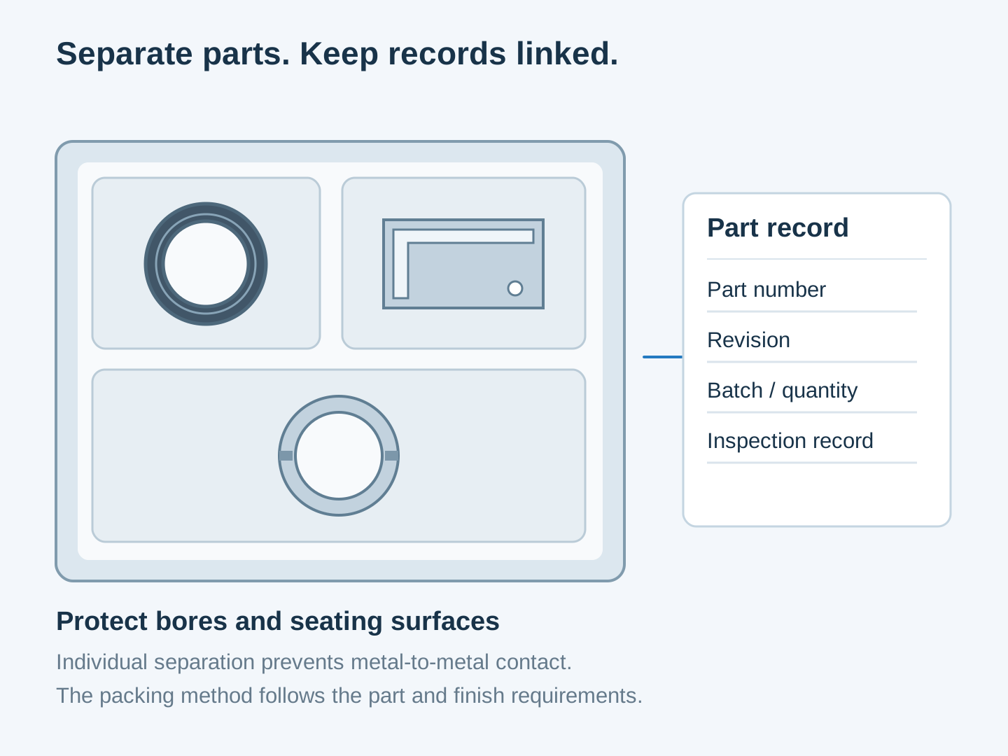
Separate packing keeps threaded rings and hard edges from rubbing against adjacent finished parts. Lens seats, exposed contact pads and black exterior surfaces receive protection appropriate to their geometry.
Spacer variants and similar retaining rings need distinct part numbers or thickness identification. Set packing can group the requested quantities without mixing parts that look alike but belong at different positions.
Parts going to optical assembly need a different handoff from parts going to a separate coating or cleaning process. The shipment scope identifies the delivered condition and any agreed records for that next operation.
No. SM1 and C-mount use different nominal diameters and pitches. They need a suitable adapter rather than direct engagement. The adapter also needs an adequate clear aperture and an axial arrangement compatible with the optical assembly.
No. Common metric breadboards use M6 holes on a 25 mm grid; imperial versions use 1/4-20 holes on a 1 inch (25.4 mm) grid. Both the thread and the spacing differ. A custom baseplate can use the required pattern or a deliberately designed conversion arrangement.
No. Thread fit does not set the load applied to the optic. Retainer contact geometry and the assembly’s preload requirement also matter; a compliant retaining arrangement can reduce stress where the optical design requires it. There is no universal tightening torque for all lens stacks.
Only when the optical component specification establishes that relationship. A mechanical edge can locate a lens in a cell, but its relationship to the optical axis is a separate centration requirement. The mount drawing and optical assembly definition must use compatible references.
Use catalog hardware when its aperture, travel, mounting pattern and envelope already suit the instrument. A custom component becomes useful when several interfaces must share one reference, the assembly must fit a restricted enclosure, or separate adapters create unwanted joints. A custom part still needs the adjustment the optical assembly actually uses.
Deburring removes unwanted edges; a controlled cleanliness level is a separate scope of work. An assembly with controlled cleanliness needs its own cleaning, verification and packaging requirements. Those requirements must be included in the ordered scope rather than inferred from a visually tidy cavity.
Not necessarily. NASA/JSC’s Type III anodizing guidance identifies reduced and uneven coating thickness inside narrow holes and tubing. Deep-barrel dimensions therefore cannot rely on an assumed equal inner and outer buildup. The finish route may need masking, a specific internal coating requirement or final machining suited to the selected process.
This page covers machined mechanical components that hold and connect optical elements. Lens grinding, optical polishing and diamond turning of optical mirror surfaces require separate processes and acceptance methods; they are outside this component service.
Interface, material and process references used for this page.
Send the component drawing or model and tell us whether you need individual parts or a complete mechanical set. We will quote the defined machining and delivery scope.
Current drawing or CAD, part numbers and the mating optical or mounting interfaces.
Quantity for each barrel, ring, holder or plate, including any separate spacer variants.
Required finish, masked surfaces, inspection records and the operation receiving the parts.
An early drawing can start the discussion; the released definition governs the build.
We use Google Analytics to see how this site is used. Analytics cookies are set only if you accept. Privacy Policy
