Multi-port imaging housings
We machine bodies with intersecting optical openings, mounting flanges and internal seats for medical imaging assemblies.
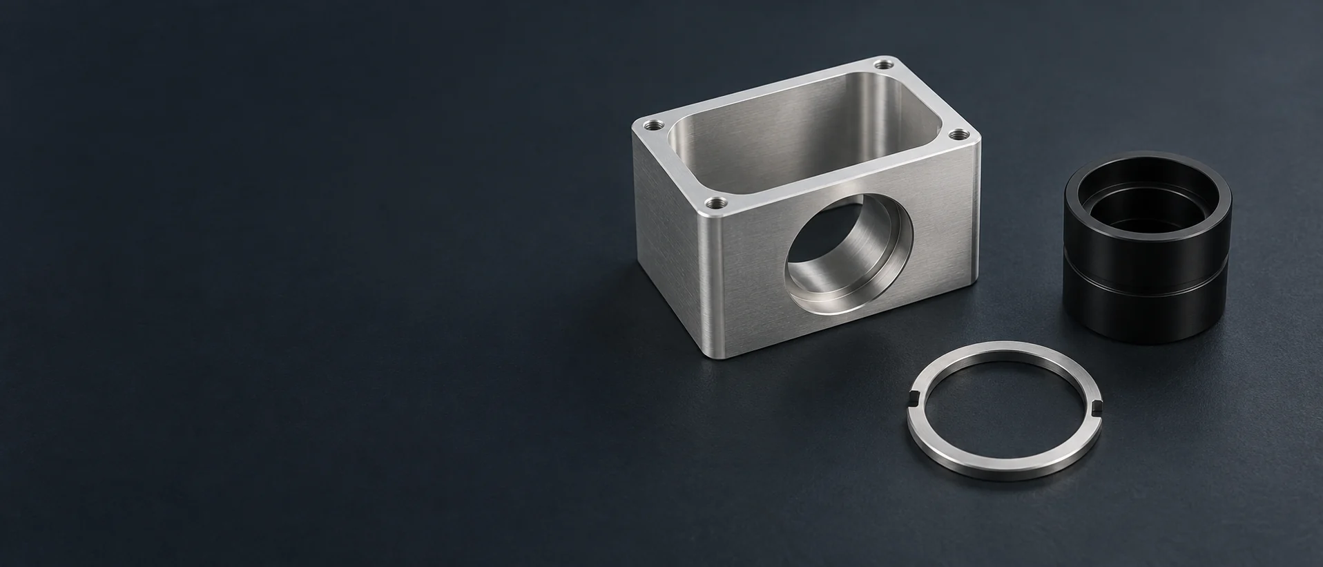
We machine bodies with intersecting optical openings, mounting flanges and internal seats for medical imaging assemblies.
Rectangular cavities accommodate sensor boards, with mounting bosses and connector openings positioned around the assembly.
Turned tubular bodies carry lens seats, retaining-ring threads and external mounting features. Milled flats or side holes can be added to the same component.
We machine oblique openings and intersecting faces for housings whose optical and mounting axes run in different directions.
Machined bodies locate an illumination module around its aperture, cable entry and attachment faces.
Removable plates close the housing or attach the imaging assembly to its instrument frame.
Threaded rings and spacers locate optical elements within the barrel. Spanner features allow access during assembly.
We machine insulating carriers and protective housings in the specified polymer, with openings for the installed instrument components.
No matching components. Try another part name or filter.
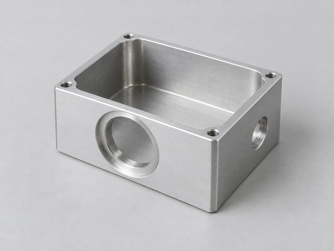
Aluminum keeps housing mass down while carrying several machined interfaces. Thin walls around a lens seat need support during pocket milling so clamping does not distort the finished interface.
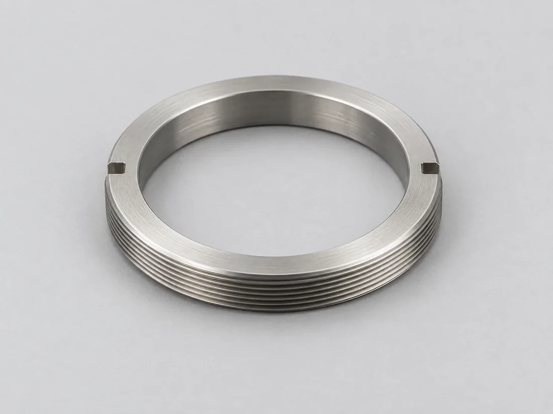
A housing body and its small threaded details need not use the same metal. A separate brass or stainless-steel insert can provide a replaceable interface without replacing the complete body.
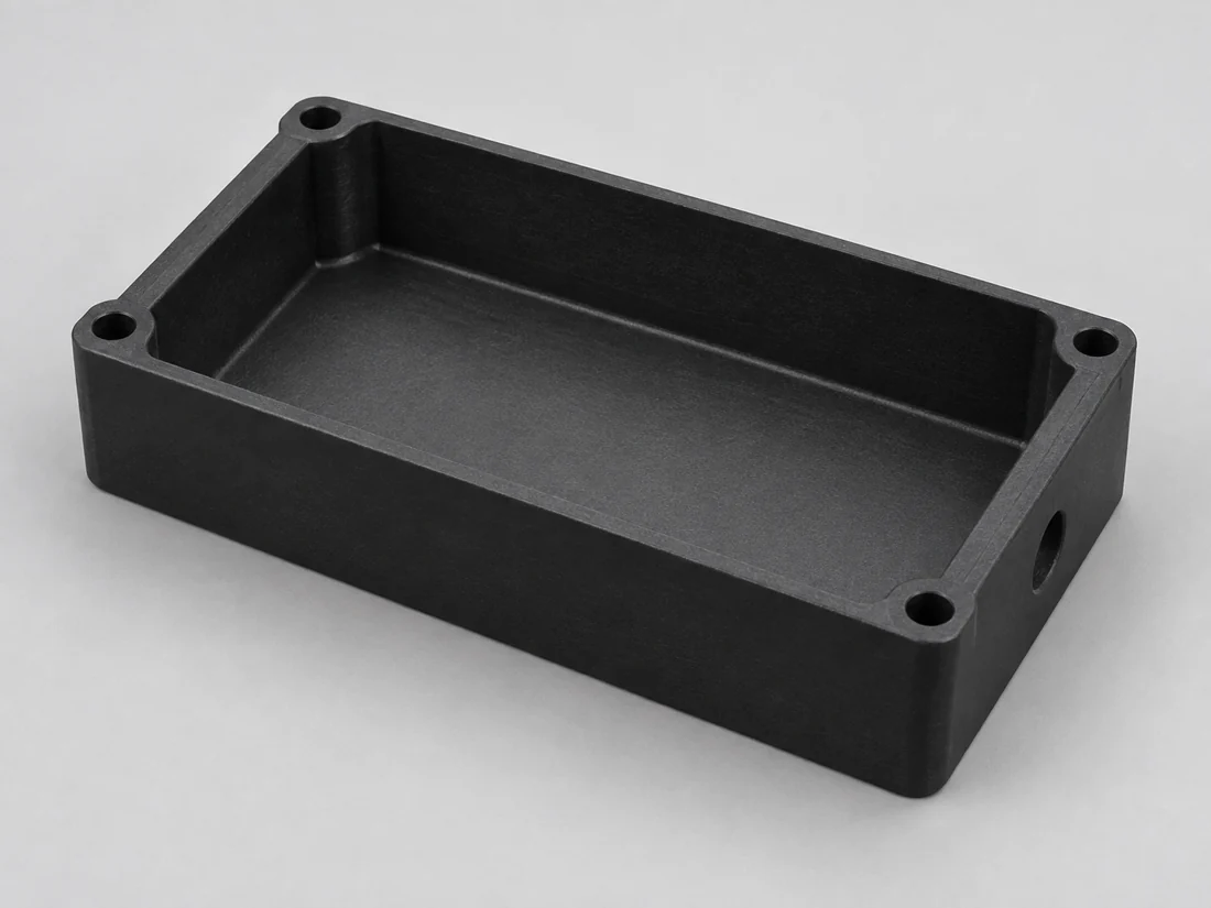
POM and PEEK are options for insulating carriers and nonmetallic covers. Use the specified grade for the component’s electrical, cleaning and exposure requirements; a material family name does not identify those properties.
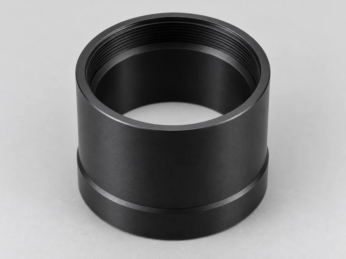
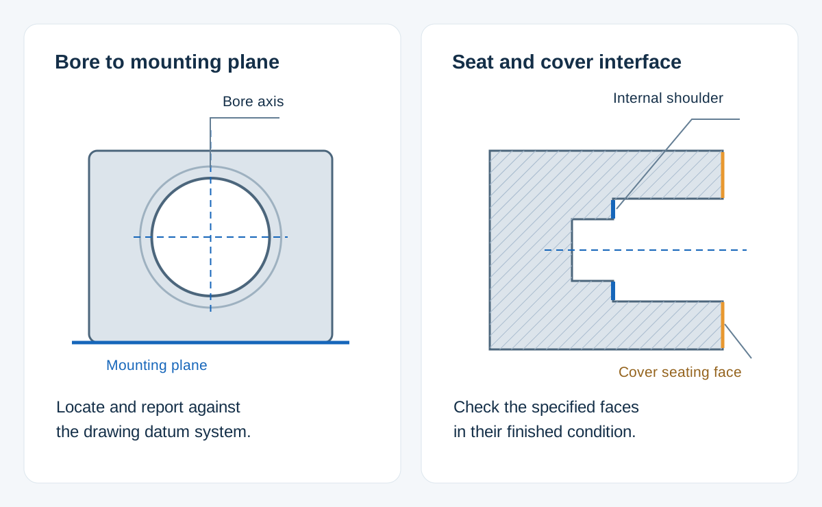
The bore locates the lens radially; its shoulder sets the axial seat. Their relationship to the mounting face must be defined. A bore can meet its size tolerance yet be misplaced relative to that face.
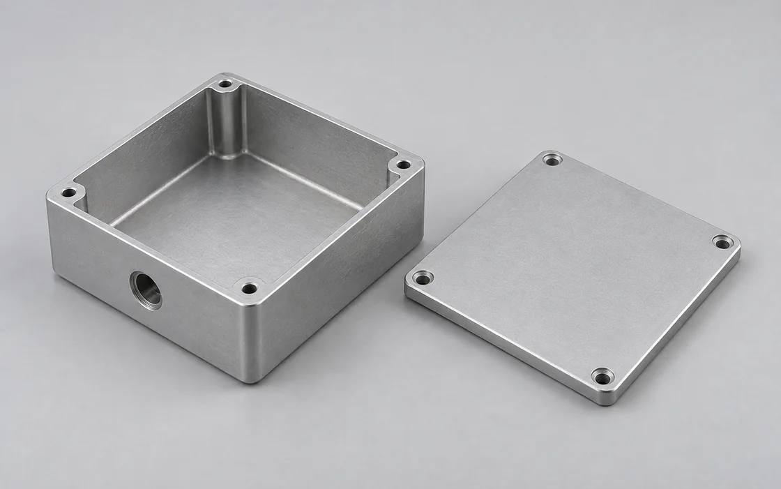
The sensor module may seat on several bosses or on a separate plate. Their height and orientation establish how that module sits behind the lens; connector clearance is a separate envelope requirement.
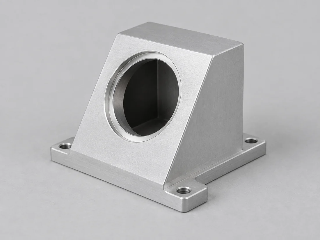
For a housing with angled optical ports, the angle and position must reference the same assembly datums. Independent dimensions from unrelated outside faces can leave the relationship between ports undefined.
| Interface | Thread | Flange distance |
|---|---|---|
| C mount | 1″–32 TPI | 17.526 mm |
| CS mount | 1″–32 TPI | 12.526 mm |
| S mount | M12 × 0.5 | No standardized distance |
| TFL mount | M35 × 0.75 | 17.526 mm |
| TFL-II mount | M48 × 0.75 | 17.526 mm |
| SM1 lens tube | 1.035″–40 TPI | Set by the optical assembly |
Flange distance is measured from the mounting shoulder to the image plane, not the overall housing length. These are interface references; the drawing defines thread class, engagement, clear aperture and dimensional tolerances. Sources: Edmund Optics, Lens Mounts; Thorlabs, SM1 Lens Tubes.
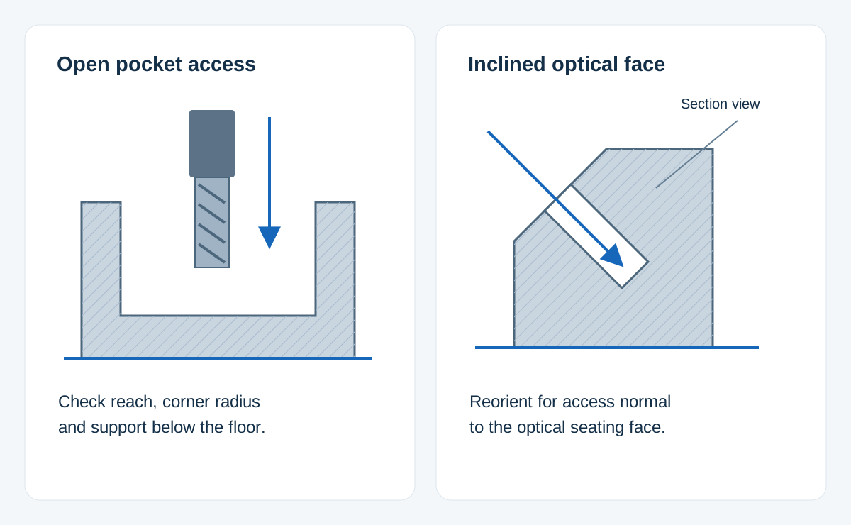
A cylindrical barrel with coaxial seats and threads starts as a turning problem. Adding a few flats or cross-holes does not make simultaneous five-axis machining necessary.
A 3+2 setup holds the part at a selected angle while the tool cuts. This can bring a port or mounting face into reach while retaining the same clamping arrangement.
Coordinated rotary motion becomes useful when tool orientation must change along a contoured surface. Deep internal seats still need a reachable tool path; extra axes do not make an enclosed feature accessible. [4]
A bare locating seat can be retained while other surfaces receive a finish. The masking boundary must leave the required contact area unobstructed.
Black anodizing changes the surface at lens threads, bores and shoulders. Critical dimensions belong in their required finished condition, with any masked surfaces identified.
For stainless details, the drawing can separate the machined surface texture from a specified cleaning or passivation process. Those requirements serve different purposes.
A housing intended for a separate optical-coating process needs that process’s substrate preparation and access requirements before machining is finalized.
We separate cosmetic exterior surfaces from optical-facing cavities in the finish scope, so the two are not accepted against the same appearance requirement. [5]
A housing report should identify the controlled bore, shoulder or mounting feature and its drawing datum. Recording unrelated outside dimensions will not verify the lens-to-sensor relationship.
Thread acceptance and full seating are separate checks. A mating component can engage the thread yet stop on a corner, burr or unfinished shoulder before reaching its intended seat.
Burrs at intersecting openings can remain inside the cavity. The drawing’s edge condition and cleanliness requirement should cover these internal surfaces as well as the visible exterior.
We quote the housing revision that matches the selected lens and sensor interfaces.
The prototype stage is where the customer checks insertion, fastener access and the complete optical assembly. A part that measures correctly can still reveal an assembly-access problem.
Once the prototype changes are accepted, the released revision becomes the batch reference. An informal adjustment to a first housing must reach the drawing before the next batch.
A replacement lens or sensor is a design change if its mechanical interface differs. Repeat orders should identify the approved revision rather than rely on the instrument’s unchanged product name.
Where a cover, spacer and body are designed as a set, include their separate part numbers and quantities. This makes the quotation’s assembly scope clear without assuming that every housing needs a new lens or sensor.
| File or requirement | Include |
|---|---|
| Housing drawing and CAD | Revision, units and datum controls |
| Mating optical module | Mount specification and installation envelope |
| Surface map | Finish, masked seats and optical-facing surfaces |
| Supply scope | Part numbers, quantities and required reports |
Agree confidentiality requirements before sending restricted instrument or product data.
A C-mount lens can be used on a CS-mount camera with a 5 mm extension that restores the mounting distance. The reverse combination does not work with a simple extension: a CS lens on a C-mount camera places the image plane ahead of the sensor. Compatibility rests on the mounting distance that places the image plane on the sensor.
Do not select the finish by visible color alone. Reflectance depends on wavelength and viewing angle; a surface that looks dark in visible light can behave differently in near infrared. The optical specification needs performance at the instrument’s operating wavelengths, whether the selected finish is anodizing or a specialty coating.
Use the assembly route to decide. A one-piece body reduces joints, but the lens, sensor and retaining hardware must pass through its openings and remain accessible to assembly tools. A removable cover or split body is useful when an internal component cannot be inserted or secured through the available port.
An existing part helps identify interfaces, and the nominal dimensions, tolerances and wear allowance are then reconciled against the mating lens and sensor. A replacement definition should reconcile the measured housing with its mating lens and sensor, then release those requirements in a drawing. Copying a worn seat can reproduce the clearance that caused the replacement.
No. A dimensional report verifies the specified mechanical features. Imaging performance also depends on the optics, sensor position and assembly. Lens installation, alignment and functional optical testing each come with their own acceptance scope.
The nominal layout may transfer, but the fit needs a new check. The lens and housing can expand by different amounts, and polymers can change dimensions under sustained clamping. The required clearance or retention should be evaluated for the actual material grade, temperature range and clamping arrangement, rather than copied from the metal version.
Share the housing drawing, mating lens or sensor interface and order quantity. We will review the component scope and machining requirements.
Interface references and machining context for this page.
We use Google Analytics to see how this site is used. Analytics cookies are set only if you accept. Privacy Policy
