Flanged sleeves
We turn the bore, outside seat and flange face as connected features. The flange locates the sleeve axially while its cylindrical contacts establish the required relationship with the retained housing or shaft.

We turn the bore, outside seat and flange face as connected features. The flange locates the sleeve axially while its cylindrical contacts establish the required relationship with the retained housing or shaft.
A hollow adapter combines its threaded ends with a wrenching section and an open passage. We machine the selected connection geometry and keep the sealing contact distinct from the thread that provides retention.
A brass mount can connect a side opening to top fixing features. We mill the locating faces and machine the related bores from the specified datums rather than center each feature independently in the raw blank.
A bezel combines an aperture, retaining thread and front flange. Its internal shoulder supports the selected insert while the flange seats on the surrounding panel; those contacts stay separate from the visible front edge.
A split collar locates a round component through its bore and fastening arrangement. We retain the drawing-defined split and wall section so tightening acts through the intended clamp geometry.
A knob joins the grip surface to its internal connection. The bore or thread establishes how it attaches; the knurled band provides the selected handling surface without becoming an uncontrolled change to the mating fit.
CW614N is a leaded machining brass suited to substantial material removal from bar. Its free-cutting behavior is useful for repeated threads, shoulders and small turned features. We retain the actual EN designation instead of purchasing a substitute under the old OT58 name alone.[1]
CW617N is a separate leaded brass used in machining and hot-formed component routes. A shaped starting blank can keep more material near a complex body while later machining completes its seats, threads and fixing faces. The preform and finished drawing remain connected.[1] [2]
A drawn rod and a softer starting form do not have identical strength and deformation behavior. The R-condition and section stay with the material record, especially where a thin collar, recessed shoulder or later assembly operation depends on the retained material state.[3]
A hexagonal blank can retain a wrenching section while its ends are turned. Flat stock can reduce unnecessary removal for a rectangular mount. A suitable form reduces cutting work, but its original corners and surface still need to leave material at the finished boundary.
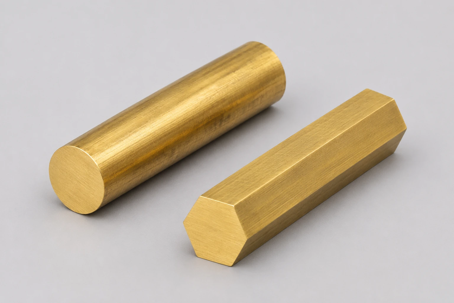
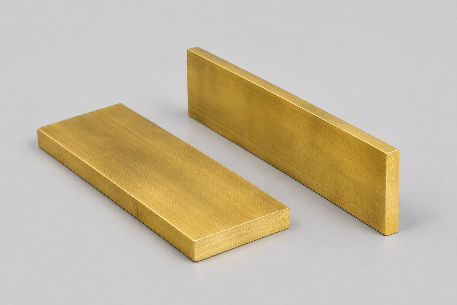
OT58 is a legacy commercial name used for more than one modern specification. TMS Metalli lists both CW614N / CuZn39Pb3 and CW617N / CuZn40Pb2 as ex OT58. The accepted EN designation, product standard and stock condition identify the material for manufacture; the short name by itself does not make the two alloys interchangeable.[4]
Both are leaded brasses. The broader brass selection page covers lead restrictions and end-use requirements; the ordered component retains its separately specified material and use conditions.
| Property | CW614N / CuZn39Pb3 | CW617N / CuZn40Pb2 | Reference condition |
|---|---|---|---|
| Lead content | 2.5–3.5 wt% | 1.6–2.5 wt% | Alumeco EN12164:2024 chemistry |
| Tensile strength Rm | 430 MPa minimum | 430 MPa minimum | R430; round rod 2–60 mm |
| 0.2% proof strength | 220 MPa minimum | 220 MPa minimum | R430; round rod 2–60 mm |
| Elastic modulus | 97,000 MPa | 97,000 MPa | 20°C |
| Thermal conductivity | 117 W/(m·K) | 123 W/(m·K) | 20°C |
| Electrical conductivity | 25% IACS | 28% IACS | Published material reference |
| Thermal expansion | 21.4 µm/(m·K) | 21.4 µm/(m·K) | 20–300°C |
Alumeco rod data, 18 March 2025. R430 rows refer to 2–60 mm round rod; physical values retain the stated temperature basis. Product-reference values are not a finished-part load or dimensional rating.

We mill the mounting faces, slots and cross features that connect the part to its assembly. Datums transfer the reference from the turned axis or existing face to the milled detail, keeping the whole interface in the same manufacturing definition.
Turning connects the bore, outside seats, end faces and axial stops. A short adapter can require several different contacts on the same axis; their finished lengths and seating surfaces matter as much as the largest diameter.
A deep bore, a narrow flange or a split collar leaves less material to resist clamping and cutting forces. We support the available robust regions and check the released state so a held round bore is not mistaken for a round loose component.
| Feature | Working requirement | Accepted condition | Verification |
|---|---|---|---|
| Bore and outside seat | Size and relationship to locating face | After specified final operations | Drawing limits and datum checks |
| Thread and seating land | Usable engagement plus distinct seal contact | Delivered finish and selected assembly state | Thread acceptance and seat geometry |
| Split collar / flange | Retained wall, split and bearing width | Released part or defined installed state | Section, face and fit checks |
| Mounting / visible face | Hole location, controlled edge and appearance | Included finishing completed | Dimensions plus agreed surface acceptance |
A thread fit, a locating bore and a visible flange face do different jobs. We finish and check each against its selected requirement instead of assigning one tolerance to every surface.
A retaining thread holds the connection together while a separate cone, shoulder or seal land may close the fluid path. We retain both definitions and their assembly clearance rather than treating a correctly gauged thread as proof of the seal.
The remaining wall carries the clamping or mounting reaction. Recesses, cross-holes and a clamp split can interrupt that path; we preserve the released section and locate secondary features from the working geometry.
A side hole or threaded port can intersect a bored passage. Access for cutting and deburring that junction belongs to the part route, so clearing the visible entrance does not leave the buried edge unaddressed.
A knob, collar or bezel needs enough usable engagement and room for its mating shoulder or insert. We retain the full connection length and runout space without extending a thread into the surface that locates the assembly.
Adapters and local port details join their passage to a selected connection seat. We supply the machined component with the agreed dimensional scope; any required pressure or leak result remains a defined additional acceptance task.
A bezel or flanged sleeve supports the insert on its intended shoulder while seating against the panel. The opening, flange and retained thickness are related features, allowing the insert to seat without loading an unintended edge.
Mounts and collars locate a retained component through a face or bore. Keeping the mounting pattern and clamping contact distinct gives each its own reference and avoids using a decorative outer profile as the assembly datum.
A knurled knob carries hand input through its thread or bore to the retained mechanism. The finished grip surface remains separate from the dimensions that locate the knob and control its axial position.

We retain the specified texture at bores, shoulders and sealing contacts. Tool marks on a non-working exterior need not be removed merely because an adjacent front face has an appearance requirement.
Edge treatment removes loose projections while preserving the intended corner and bearing width. Narrow internal junctions need a reachable removal route rather than only an exterior brush pass.
A front bezel or knob can receive an agreed directional or polished appearance. Its visible edge, lettering and adjacent contact surfaces remain within the released geometry through finishing.
We protect bright faces and keep marking away from the working contact. Any included plating retains its specified coverage and final fit; part identity distinguishes similar components with different stock conditions.

The stock record identifies CW614N or CW617N and its ordered condition. That identity stays connected to the machined component rather than being replaced by a generic OT58 description at receiving.
We relate bore and outside sizes to the locating faces, then check thread, hole and edge requirements in the delivered condition. A dimensional record identifies the part revision and the surfaces actually accepted.
A fluid, electrical or assembly-performance result needs its defined test and acceptance. Material chemistry and a dimensionally correct component provide different evidence from that additional functional result.
Round or hexagonal bar can share efficient turning preparation. A flat blank can reduce removal for a mount, while a shaped preform introduces its own preparation and datum route before the final contacts are cut.
A turned adapter with cross-holes, flats or a local pocket needs additional tool directions. Narrow bores and fragile flanges can require extra support or intermediate handling even when the overall part is small.
An appearance face, included coating or recorded close-fit inspection adds work to the component. Keeping those requirements on the surfaces that need them avoids extending the same costly operation to the whole exterior.
Programming, fixture preparation and first-part checks are spread across the ordered quantity. Shared geometry can reuse that preparation, while changed grades, conditions or delivered finishes create separate work.
The released component connects its EN grade, product form and condition to the finished drawing.
The first part resolves support, connected features and the inspection access for the controlled contacts.
The accepted datum setup and finishing sequence accompany the batch so the completed contacts have a consistent definition.
A changed fit, thread or material condition stays in the new revision instead of being mixed into an otherwise similar component.
No. R is a tensile-strength condition designation under the EN1173 system used by EN12164; R430 identifies the minimum tensile-strength requirement, not a named furnace cycle. It also does not convert directly to a hardness condition. Retain the full ordered material condition rather than infer a thermal history from those digits.
No. Alumeco states that index relative to CuZn39Pb3=100. It is a comparative material reference, not a prescribed speed, tool-life ratio or cycle-time percentage. The actual tool, section and operation still determine the cutting route.
That needs a separate forming decision. Alumeco rates cold formability poor/not recommended for both cited grades even though their machining ratings are high. A thin lip that must flare or bend is therefore not approved by the alloy’s free-cutting description; its material condition and intended deformation need a suitable released forming route.
No. In Alumeco’s cited data, soldering is rated excellent while TIG and MIG welding are rated poor/not recommended. These joining methods impose different thermal conditions. A soldered design cannot be converted to a fusion-welded connection merely by retaining the same OT58 component outline.
No. ASBW’s stated diameter classes describe its incoming round rod. A turned bore, pilot or flange is a new feature with its own reference and finished limits. The raw-bar tolerance can affect available machining stock, but it is not acceptance of the completed mating surface.
No. Alumeco gives mechanical polishing a good-to-excellent rating and electrolytic/chemical polishing a poor/not-recommended rating for these grades. They are not interchangeable routes to the same result. The selected process must preserve the required appearance, contact geometry and edge condition on the actual component.
Send the component drawing, accepted CW designation and stock condition, quantity and final contact requirements. We can define the turning, milling and included finish for that part.
Sources for named rod properties, material condition and legacy OT58 usage.
We use Google Analytics to see how this site is used. Analytics cookies are set only if you accept. Privacy Policy
