Insulating barriers
A profiled barrier separates adjacent conductive hardware. Its outline, mounting holes and local openings must leave the intended insulating material between the installed components.

A profiled barrier separates adjacent conductive hardware. Its outline, mounting holes and local openings must leave the intended insulating material between the installed components.
Terminal support strips carry a repeated opening pattern in a common laminate section. Hole pitch and the material between neighboring openings determine how the mounted terminals are positioned.
A pocketed plate combines an assembly reference face with local clearance. The pocket floor and mounting lands retain different thicknesses, so the bottom of the recess is not automatically the locating surface.
A washer separates fastened faces while passing the bolt through its bore. The remaining annulus carries the contact, and the outer profile must clear nearby conductive hardware.
A support block can include a seat, step and attachment pattern in one piece. The mating surface locates the supported component; clearance pockets provide access without taking over that job.
A carrier positions components around a circular pattern or central opening. Local openings and the outside rim must remain connected by enough material for the specified handling and support conditions.
We quote drawing-defined G10 and FR4 components with milled profiles, pockets, holes and specified finished faces. These are machined laminate parts; electrical-system qualification and PCB fabrication are separate activities.
G10 and FR4 share a woven-glass epoxy construction, but the grade names do not authorize automatic substitution. Norplex describes the NEMA distinction that excludes bromine and other halogen flame retardants from G10 and G11.[2]
Norplex NP510A is a brominated FR4 product. A named manufacturer grade connects the ordered laminate to its actual data and recognition; a generic FR4 label does not identify every available formulation.[2] [1]
Lengthwise and crosswise properties differ in woven-glass sheet. Orienting the same outline differently in the blank can change the material direction carrying a bent tab or loaded support.[1]
A deep recess leaves a different laminate section from the full-thickness stock. The remaining floor, attachment lands and webs each carry their own portion of the component geometry.
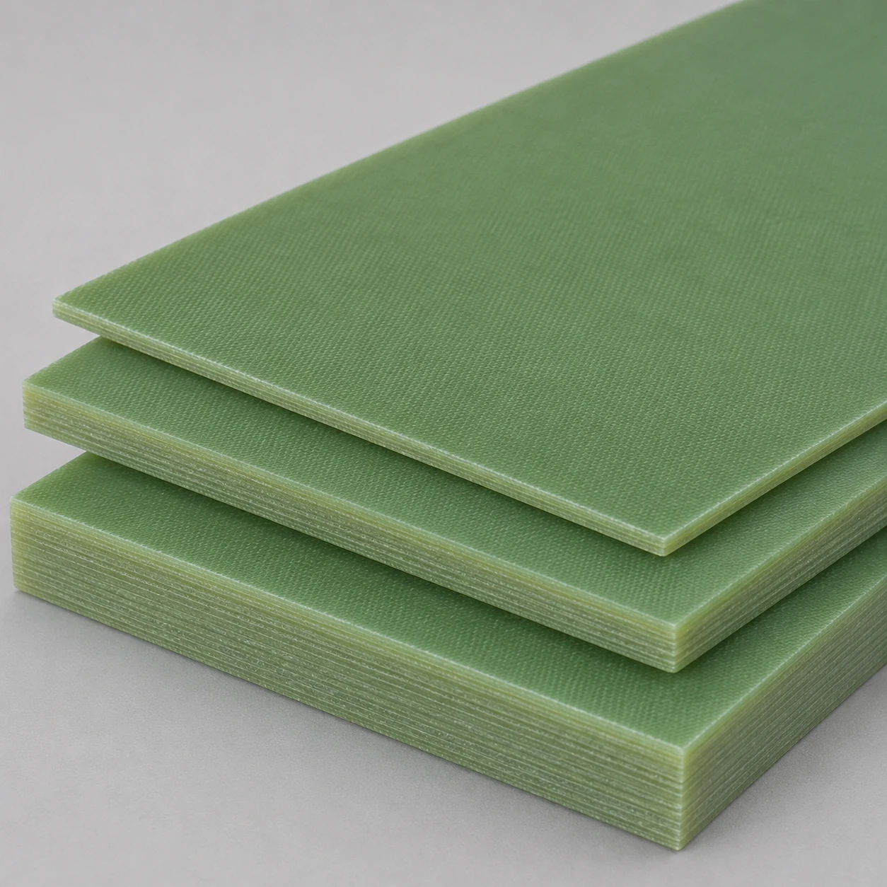

A cut part retains the laminate construction and direction selected in the blank.
| Property | Reference value | Test basis | Specimen / direction |
|---|---|---|---|
| Specific gravity | 1.85 | ASTM D792 | 0.500 in |
| 24-hour water absorption | 0.10% | ASTM D570; D1-24/23 | 0.0625 in |
| Flexural strength | 448.2 / 358.5 MPa | ASTM D790; Condition A | LW / CW; 0.0625 in |
| Flexural modulus | 20.0 / 17.9 GPa | ASTM D790; Condition A | LW / CW; 0.0625 in |
| Tensile strength | 275.8 / 220.6 MPa | ASTM D638; Condition A | LW / CW; 0.125 in |
| Compressive strength | 455.1 MPa | ASTM D695; Condition A | Flatwise; 0.500 in |
| Shear strength | 148.2 MPa | ASTM D732; Condition A | Perpendicular; 0.0625 in |
Norplex-Micarta NP510A TDB, 14 July 2022. Typical values for this FR4 product; LW/CW means lengthwise/crosswise. Test directions, specimen thicknesses and conditioning are retained for comparison.

Glass fabric is abrasive to cutting edges. Norplex recommends carbide tooling for glass-based laminates; edge wear can affect a run before the outline itself changes.
A contour cut passes across the reinforced layers. Cutter engagement and supported sections drive edge integrity, so the cut edge is inspected on the edge itself.
The exit side of a drilled hole can chip where the laminate loses support. A backed exit and suitable cutting method address that edge separately from the finished bore diameter.[3]
Inspect the released or specified mounted part. Material coupon data do not supply a universal component tolerance.
| Feature | Drawing requirement | Accepted condition | Verification |
|---|---|---|---|
| Mounting-hole pattern | Size and location to datum | Released / specified mounted state | Size and position check |
| Fastener seat | Depth and retained bearing land | After edge cleanup | Depth and land inspection |
| Pocketed plate | Floor and mounting-face relationship | At defined supports | Datum-based geometry |
| Cut edge | Permitted chip / delamination condition | Finished critical edge | Edge examination |
The drawing identifies the functional references and required condition. Material coupon properties and geometric inspection do not replace a separately specified electrical or assembly test.
We relate the finished openings, bearing lands and support faces to the drawing’s mounting references. Any separate dielectric or assembly test has its own defined scope.
Closely spaced holes leave narrow ligaments. Their width and position relative to a loaded opening affect the retained component section, not merely the quantity of material removed.
A fastener recess removes material beside its hole and beneath the head. Keeping the complete bearing footprint inside the retained section avoids turning a full seat into a partial edge contact.
A milled corner retains a cutter radius. The mating component’s corner relief and entry path determine whether it reaches the intended seating face.[3]
Rotating parts to improve sheet yield can rotate their laminate direction too. Nesting follows the direction requirement when the part uses that material distinction.
A barrier’s position determines which hardware it separates. Mounting clearances and openings belong to the equipment design rather than an assumed insulation rating for any machined shape.
A common support pattern keeps several terminal positions related. Replacing a strip includes the installed mounting pattern, so an individually matching bore is only part of the replacement geometry.
A fixture pocket can locate a component while local relief clears projections or tools. Giving these surfaces separate jobs makes the intended contact visible in the part definition.
A spacer or carrier establishes a position within an assembly stack. Its working faces and the intervening hardware determine that position; the unused stock face is not automatically an accepted assembly datum.
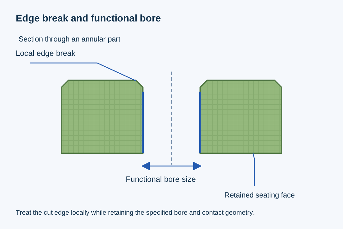
The required face texture belongs to the contact it serves. A broad cosmetic sanding operation can remove material from a face that sets the mounted thickness.
A specified edge break removes a sharp intersection. It must not consume the narrow land around an opening or change a locating bore into a tapered entrance.
Loose fragments at a pocket corner or hole exit can interfere with seating and handling. The accepted edge condition is defined separately from the nominal outline.
An engraved mark changes the local surface. Its location and depth can be kept away from a thin insulating web, bearing land or finished locating face.
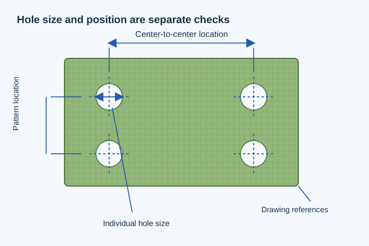
The material record identifies the ordered glass-epoxy grade and product. Where direction matters, the blank-to-part layout carries that orientation into the finished component.
Cut-edge inspection can address chips, exposed fibers and delamination at critical openings. A size report does not describe these local edge conditions.
The dimensional record follows the part’s actual mounting references. Any specified electrical verification remains a separate test of the stated part or assembly condition.
The outside blank, direction and nesting determine yield. A small finished outline can still need more sheet area when narrow features require retained support during machining.
Tool wear and edge-control work add cost beyond the material removed. A long perimeter with many small openings can require more cutting effort than a larger simple plate.
Opposed recesses or finished thickness faces need their relationship maintained across the work. They add setup and inspection work compared with a one-sided outline.
Preparation and first-part verification can be spread across a repeated run. A changed laminate construction or mounting pattern can alter that preparation rather than inheriting the old setup.
The released part combines its material construction, direction and functional geometry. That is the baseline for the quoted machined component.
The first-part result establishes the actual opening pattern, finished section and critical edge condition against that baseline.
Repeat production retains the drawing and material revision. A change to either receives the corresponding manufacturing and acceptance adjustment.
Packing separates thin edges and finished faces from abrasion or bending during handling. The shipment retains the part and material identification used for the order.
No. Norplex’s fabrication guide notes that drilled laminate holes can finish below the drill size. Acceptance follows the actual finished bore; the tool marking alone does not account for cutting condition and the chosen finishing method.
No. Tg describes a resin transition measured by the stated method. The bulletin lists temperature-index data separately and says the operating limit depends on the application. Neither the Tg number nor a brief exposure establishes the service condition of a finished insulating part.
No. The bulletin reports that flame result at a tested thickness of 0.0625 in. A thinner section cut into a part needs matching evidence at that thickness. The required material recognition and finished thickness need matching evidence.
It can be a design option. Norplex’s guide calls for sanding and cleaning before a two-part epoxy suited to the environment. Joint geometry, the metal preparation and the actual exposure determine the bonding system, and bond strength is confirmed by testing that joint.
Yes. Norplex’s guide recommends predrilled pierce locations to prevent delamination. That concerns preparation of the supplied blank, separately from the later CNC features and dimensional acceptance; the cut route should preserve the material needed for those features.
It is a different construction. Copper foil adds a conducting layer to the laminate faces, changing the electrical and machining interfaces. Isola’s PCB-laminate offerings explicitly include foil types and weights; the bare NP510A reference table here does not qualify that copper-clad construction.
Send the part drawing, named laminate grade, thickness, direction requirement and quantity. Identify the working faces, critical edge condition and any separately included electrical or assembly acceptance.
Named material data and fabrication guidance support the distinctions used on this page.
We use Google Analytics to see how this site is used. Analytics cookies are set only if you accept. Privacy Policy
