Stepped shafts
We turn the working diameters, shoulders and end features of 304 shafts. Milled flats, slots or cross-holes can be related to the shaft axis where the drawing requires a drive, mounting or adjustment feature.
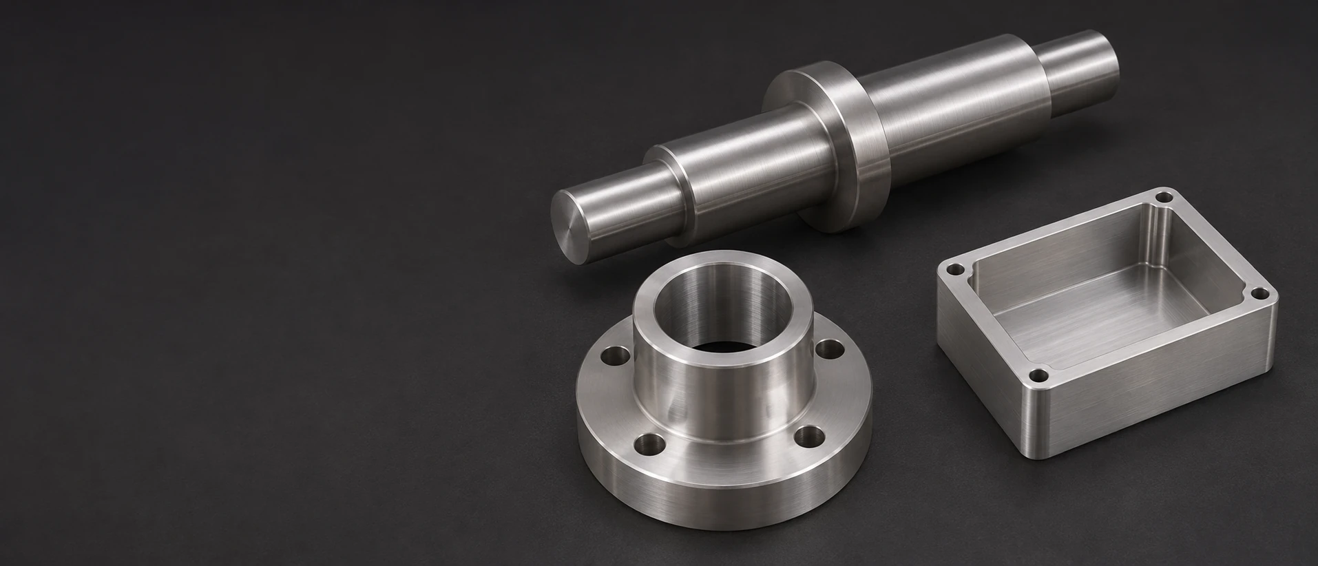
We turn the working diameters, shoulders and end features of 304 shafts. Milled flats, slots or cross-holes can be related to the shaft axis where the drawing requires a drive, mounting or adjustment feature.
Flanged couplings combine a center bore or spigot with an axial seating face and bolt pattern. We machine these interfaces into the stainless body, including specified recesses or reliefs around the connected components.
We turn internal or external threads, seating diameters and shoulders on drawing-defined adapters. Wrenching flats, a through bore or secondary openings follow the actual connection rather than a generic outside thread size alone.
A mounting block combines reference faces with hole patterns, slots or pockets. We mill those features into the selected 304 blank so that the supported item is located from the faces and datums specified on the drawing.
We machine equipment cavities, cover lands and mounting features in stainless sensor bodies. Probe or cable openings can connect to the cavity, while the local wall and attachment pattern follow the intended device arrangement.
Turned 304 rings provide a defined bore, outside profile and axial spacing. A step, counterbore or relieved edge can be included where the ring meets the mating shoulder or neighboring hardware.
VETCNC quotes drawing-defined 304-family and specified SUS304 turned and milled parts. We retain the ordered product standard, stock condition, finish and final acceptance; polishing is included for the identified surfaces when specified.
304 is a chromium-nickel stainless choice for general mechanical components. The named Sanmac 304/304L reference below is a specific low-carbon bar product, with nominal 18.5% chromium and 8.5% nickel. Its published values describe that product and condition rather than every form sold as 304. [1]
A low-carbon requirement matters where later welding or heat exposure could affect intergranular-corrosion resistance. The ordered 304L or certified combined designation stays with the component definition. Welding and its final surface and dimensional work are included only as defined for the assembly. [1] [1]
Round bar suits shafts, adapters, couplings and rings. Its delivery condition provides the starting material basis for machining. The table uses solution-annealed Sanmac bar; a cold-worked product would need its own ordered condition and properties. [1]
A rectangular blank can suit a mounting block or pocketed housing with broad reference faces. The selected product form and allowance need to cover the retained wall, pocket and mounting features. Bar reference values are not silently transferred to plate or another delivery condition.
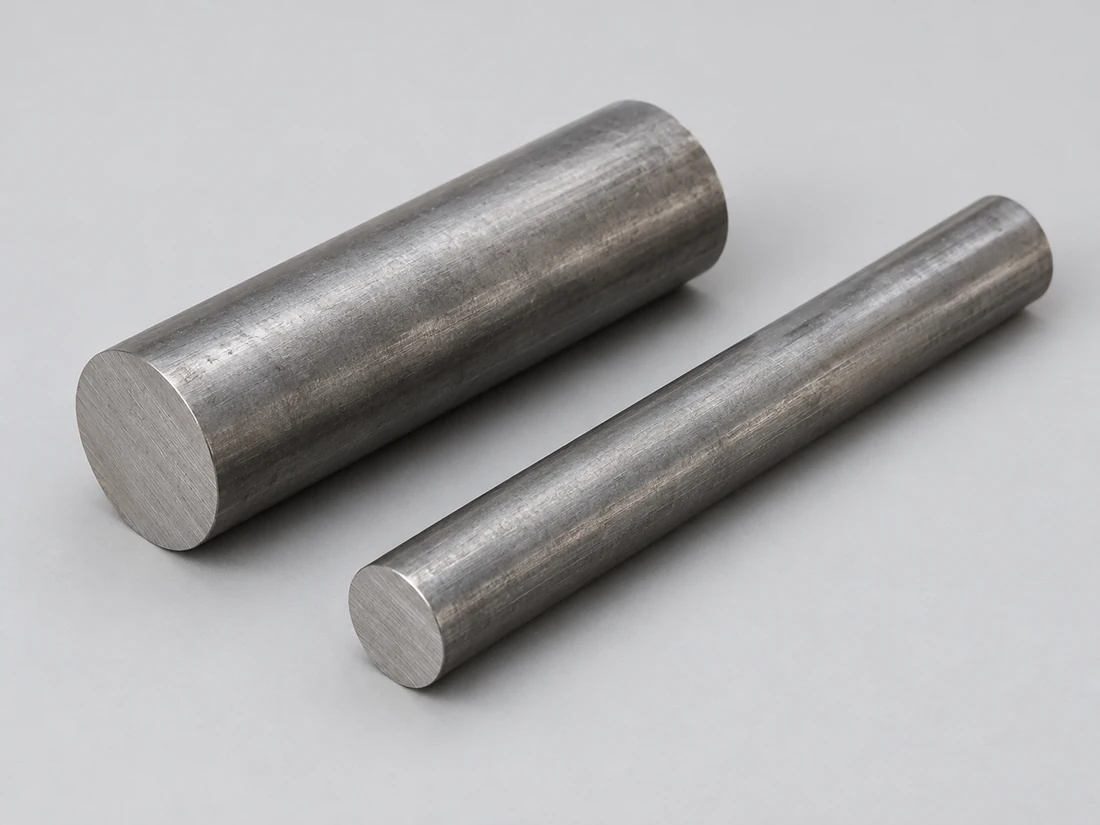

The stock condition establishes the material basis; the finishing route establishes the supplied surface and final feature state. A bright exterior cannot substitute for the specified strength, and a suitable bar does not by itself establish the finish on a fitted diameter or visible housing face. [1] [2]
The table separates the named bar’s delivery-condition mechanical limits from its physical reference properties.
| Property | Published value | Unit | Condition / basis |
|---|---|---|---|
| 0.2% proof strength, Rp0.2 | ≥205 | MPa | Bar delivery condition; 20°C |
| Tensile strength, Rm | 515–680 | MPa | Bar delivery condition; 20°C |
| Elongation, A | ≥45 | % | L₀ = 5.65√S₀; 20°C |
| Brinell hardness | ≤215 | HB | Bar delivery condition; 20°C |
| Elastic modulus | 200 | GPa | Physical reference; 20°C |
| Density | 7.9 | g/cm³ | Producer physical reference |
| Mean linear expansion | 16.5 | µm/(m·K) | 30–100°C interval |
Alleima Sanmac 304/304L Bar Datasheet, updated 09 May 2025. Round bar is supplied solution annealed and peel turned; mechanical properties are tested in delivery condition at 20°C. The first four rows retain the producer’s stated mechanical limits; the last three are physical reference values. Plate, hollow bar and other 304 products each carry their own product requirements. The ordered product specification governs the supplied material.

We relate shaft seats, adapter threads and flange faces to their working axis. Tool condition, chip control and a stable cutting setup matter in 304; rubbing or a built-up edge can compromise the surface intended for a later fit or polish.
Milling adds the bolt pattern, mounting flats, equipment pocket and connection openings. The setup references the working bore or face where those features need to align with the turned geometry, rather than locating each face independently.
Austenitic 304 can work-harden as it is deformed. The cutting plan therefore keeps the tool cutting effectively rather than dwelling or repeatedly rubbing the same track. The actual stock, tool access and retained section determine the machining conditions. [1]
Final acceptance identifies the applicable machining, polishing and treatment stage for each feature.
| Feature | Requirement | Final acceptance stage | Verification |
|---|---|---|---|
| Shaft seat and shoulder | Drawing diameter and axial datum relationship | After finishing included on the seat | Diameter / face relationship |
| Coupling bore and flange | Drawing bore, face and bolt-pattern datums | After required machining and surface work | Bore / face / hole-location check |
| Threaded adapter | Drawing thread and seating requirements | After any finish affecting the thread | Specified thread and shoulder checks |
| Selected polished area | Drawing texture, lay or agreed appearance | After final polishing and cleaning | Required surface measurement / appearance check |
Finishing coverage, protected areas and any removal allowance are defined for the component. Final size, texture and appearance are separate acceptance items; a bar-supply finish or abrasive label is not a finished-part tolerance or universal roughness guarantee.
We quote the bore, shaft seat, thread and selected surface requirements on the actual drawing. The final dimensions and inspection method include the specified finish route; there is no single removal allowance or accuracy value that applies to every polished 304 component.
A visible polished band and an adjacent bearing or locating track can require different surfaces. Defining where one zone ends keeps the finishing operation from blending across the functional boundary. That boundary should be reachable without using the fitted track as a holding surface.
A bolt circle may need a defined angular relationship to a flat, slot or other drive feature. The circle diameter and number of holes alone do not fix that clocking. The component datums establish how the connected parts line up.
A sensor housing needs a continuous cover land around the equipment cavity. Pocket corner radii, cable entries and attachment holes must leave that land where the cover seats. A local clearance relief can solve corner interference without removing the entire seating edge. [2]
If the component receives a welded tab or another attachment, the final position of its working references needs to follow that fabrication sequence. A tightly controlled face or bore may need its final acceptance after the attachment rather than only before it.
A stepped shaft positions the rotating components through its seats and axial stops. A flat, slot or end attachment transmits or retains the connection as designed; the shaft’s stainless grade does not itself establish a wear rating for a sliding interface.
A removable flange connection needs room for the mating components to enter and separate along the intended assembly direction. Fasteners also need tool access with the surrounding equipment in place, so the connection can be opened for the required service work.
An adapter brings one defined thread, seating face or mounting diameter to another interface. Wrench access and the actual stop position make the connection usable in the equipment. A machined adapter is not assumed to be a certified pressure fitting.
A mounting block or sensor body positions the inserted item relative to the equipment. Pocket depth, probe axis and attachment faces establish that position, while the enclosure leaves the required access for the cable, cover and service tools.

Bores, thread forms and locating faces can remain as machined where they meet the drawing’s surface requirement. Tool marks and entry edges are accepted for their function; a uniform exterior shine is not required on every hidden or fitted feature.
Mechanical polishing establishes the specified texture or appearance on the identified surfaces. Access and polishing direction affect the result, especially beside recesses or changes of section. The finish plan preserves the required edges and mating geometry instead of blending the whole component indiscriminately.
Where specified, chemical passivation follows the required preparation and acceptance route for removing free iron and other surface contamination. It has a different purpose from abrasive polishing. The treatment and required evidence are identified for the actual part and surface condition.
Electropolishing removes surface metal while modifying the surface condition. Its selected coverage and process allowance are coordinated with threads, fitted bores and edges, with the final feature checks performed at the required stage. It is not treated as an added coating thickness.
The part record retains the ordered grade designation, governing product specification and supplied condition. Required material evidence is agreed for that order rather than inferred from an unmarked bright surface or a generic stainless label.
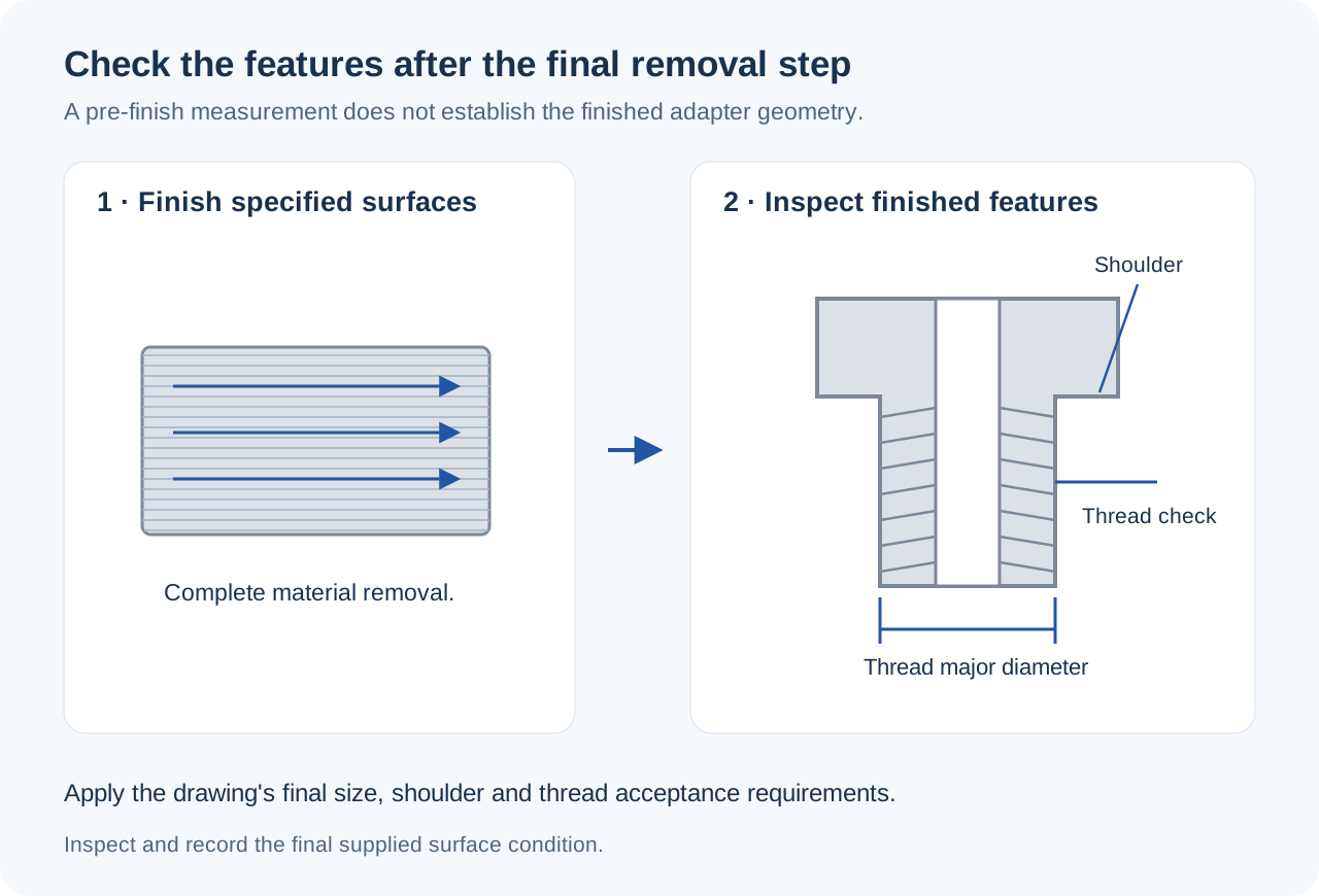
We inspect the selected fitted diameters, threads and shoulder relationships after the material-removal steps included for those features. A final thread or bore result is compared with the released limits, rather than carried over unchanged from the earlier turning measurement.
The finish requirement defines the selected areas, texture or appearance and any specified treatment checks. Those results are recorded within the agreed scope. Surface-treatment effectiveness and the geometry checks are reported separately, each against its own acceptance basis.
The required product standard, supplied condition and source restrictions affect sourcing. A large-bore ring removed from solid bar uses material differently from a compact shaft or a block laid out from a rectangular blank.
Long bores, slender reaches and interrupted features can require added support or cutting steps. Threads, flange holes and housing pockets on several faces add setup work beyond a simple rotational outside profile.
The extent and accessibility of polished faces change finishing effort. Protected fit zones, an agreed appearance sample and recorded final texture or thread checks also add defined work. The quote includes the actual surface route rather than a general polished-part label.
Programming, workholding and first-part checks are divided across identical parts produced together. Different adapters or finish variants retain their own preparation. An unchanged repeat can reuse the accepted drawing and process basis.
An initial component checks seating, connection access and the selected mating geometry. The accepted result identifies any drawing change needed before the remaining quantity follows that definition.
The representative component uses the intended material condition and finish route. Where visible appearance matters, the accepted face or sample defines that result alongside the measurable feature requirements.
The material product, drawing revision, finish coverage and required checks define the production run. Agreed changes are carried into that released definition rather than remaining an undocumented adjustment on one sample.
Repeat supply references the accepted part and finish definition. A changed stock condition, source or surface process is identified before it enters the same equipment, so the affected fit, material and appearance requirements can be reviewed.
Not by itself. SUS304 is a JIS designation, while an ASTM order also identifies a product specification and its applicable requirements. Alleima’s cross-reference lists related designations for its own product; it does not qualify every bar sold under one of those names. The supplied material evidence must support the actual standard and condition required by the order.
Handheld XRF does not measure carbon, so an XRF alloy-family result alone cannot verify the low-carbon requirement. Where carbon verification is required, use suitable material evidence or an agreed carbon-capable analytical method. The method and its scope are specified for the order; a generic PMI label does not tell us which elements were actually measured.
No. Cold work can create a magnetic response in 304 through deformation-induced martensite. Carpenter notes that chemistry and working history affect permeability. Grade identification therefore comes from the material record rather than a hand magnet. If low magnetic permeability is a functional requirement, define the required property and test separately.
Grit identifies a process input, not a guaranteed conversion to final Ra. Starting surface, abrasive condition, polishing route and measurement direction affect the result. BSSA reports substantial variation in surfaces described by a common grit finish. Specify the required roughness and relevant direction when texture matters, and define appearance separately where the part is visible.
No. Stress-corrosion cracking depends on the combination of tensile stress, temperature and a susceptible environment. Alleima warns of this risk above about 60°C in certain solutions, particularly chlorides. That observation is not a guaranteed safe boundary below 60°C. The actual exposure and stresses need a corrosion assessment alongside the mechanical requirement.
No. Surface texture and surface contamination are different results. Carbon-steel tools, wire brushes or grinding dust can leave iron contamination that rusts on stainless steel even when the surface looks smooth. BSSA recommends segregation and appropriate cleaning of shared equipment. The surface route must address that contamination rather than rely only on the Ra reading.
Send the matching drawing and model, grade and product standard, stock condition and quantity. Identify the working fits, polished areas and required final records so we can quote the machining and surface route for the intended part.
Named bar data and the specific verification and finishing guidance used for the decisions on this page.
We use Google Analytics to see how this site is used. Analytics cookies are set only if you accept. Privacy Policy
