On this page
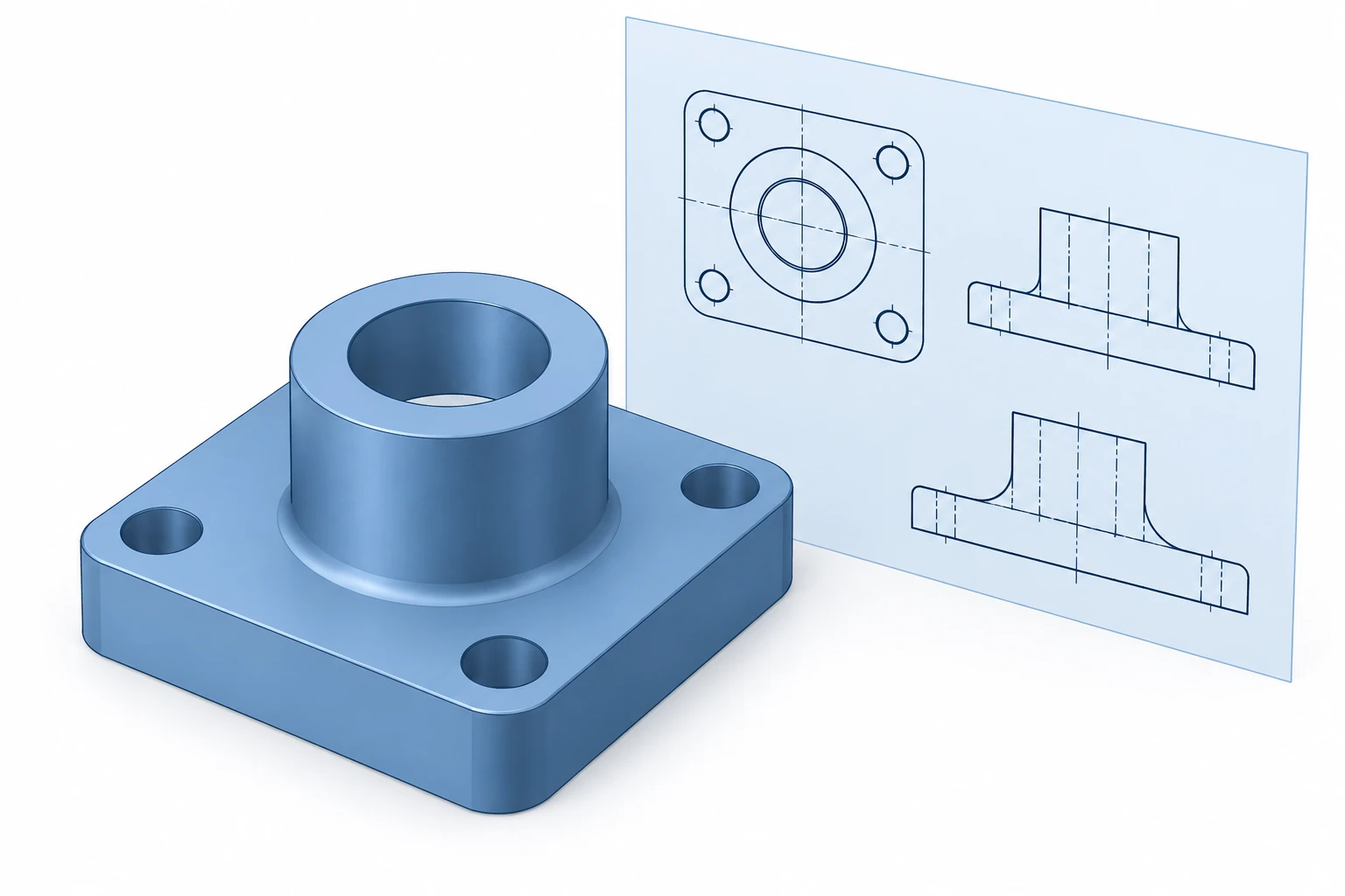
For a 3D mechanical part, a STEP solid model is a practical starting point for CNC file exchange. Confirm the receiving CAD/CAM system’s requirements; Parasolid or the native CAD file may be a better fit for that workflow. A planar profile may suit DXF, while an STL needs a different review because it describes a triangular mesh. The useful choice depends on the data the recipient needs, not just the extension. [1] [2]
Send the manufacturing requirements alongside the geometry, in the agreed drawing or model-based definition. Then check the actual exported file: a successful save does not prove that its size, bodies or annotations survived translation.
Choose a format for the information you need
A CAD exchange format carries design data into another application. It is not, by itself, a machine-ready CNC program. This table distinguishes common handoff uses; the receiving software and export settings still determine what can be used.
| Format | Useful handoff | Check before sending |
|---|---|---|
| STEP · .step, .stp | 3D part or assembly exchange | Solid/surface content and required annotations |
| Parasolid · .x_t, .x_b | Compatible solid-model workflow | Receiver’s supported version and body type |
| IGES · .igs, .iges | Agreed curve, surface or solid exchange | Entity types, joined faces and gaps |
| Native CAD · e.g., .sldprt | Direct collaboration or supported translation | Version, configuration and referenced files |
| STL · .stl | Mesh-based geometry workflow | Units, mesh quality and CAM compatibility |
| DXF / DWG | Agreed profiles or drawing data | Actual entities, scale, layers and missing depths |
| PDF drawing | Readable dimensions, notes and requirements | Revision, legibility and complete definition |
These formats are not interchangeable containers for identical information. STEP and IGES can contain different geometric representations; even a file accepted by the application may arrive as surfaces rather than the intended solid. [1] [3]
STEP, Parasolid and IGES: inspect the received model
A solid boundary representation, or B-rep, describes the faces and their connections around a volume. For a part designed as a solid, confirm that it still imports as the expected solid body. A collection of separate surfaces may need repair before the intended manufacturing workflow can use it.
IGES is not limited to disconnected surfaces. SOLIDWORKS, for example, offers trimmed-surface, solid B-rep and wireframe export options. The selected entities and the recipient’s support matter more than a blanket rule that every IGES file is unsuitable. [3]
Choose Parasolid or native CAD when the receiver confirms the format and version. Onshape explicitly prefers Parasolid for import and also supports several other systems’ native files. Cross-system support does not establish that every original feature, constraint or editing operation will remain available. [2]
STEP can also carry product and manufacturing information (PMI), including dimensions and tolerances. Check the exported and imported content before relying on it: visible annotations and software-interpretable PMI are different forms of information. An AP242 selection alone is not proof of a complete manufacturing definition. [1]
What changes when the only file is STL?
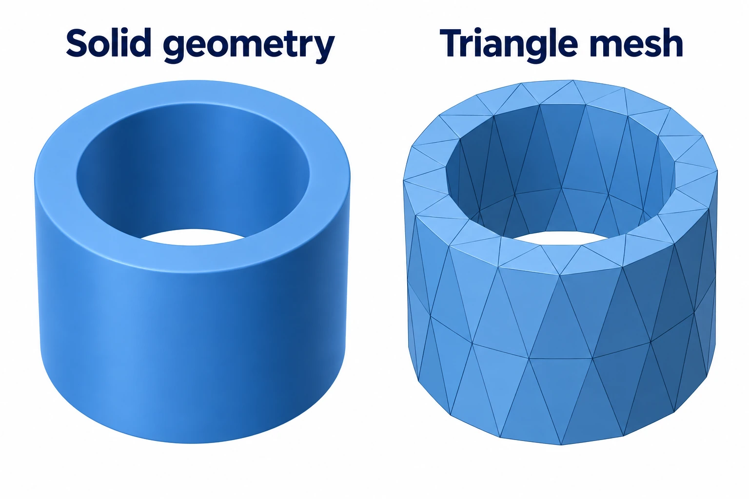
STL stores the surface as triangles. A circular bore is therefore represented by facets rather than the original continuous cylindrical surface. A finer mesh can approximate the shape more closely, but the extension does not tell you whether the approximation is adequate for a particular feature. [4]
Mesh geometry can be machined in compatible workflows. Autodesk documents mesh use in Fusion toolpaths, so “STL can never be used for CNC” is too broad. Confirm the supported operations and how the mesh will be checked; being able to display it is a different capability from using it for machining. [5]
Converting STL to a solid does not automatically recover the original design. Fusion’s faceted conversion creates a face from each mesh face; its prismatic method infers features from face groups. Neither process establishes the designer’s intended bore size or fit tolerance. If the original solid exists, request it. If only a scan or mesh remains, agree how reconstructed geometry and functional features will be validated. [6]
DXF profiles need depth and feature context
For a planar machining contour, a clean DXF profile can be useful. Specify units and identify the intended cutting geometry. Check for open contours, duplicate entities and reference layers that should not become machining boundaries.
Do not confuse that profile with a complete drawing sheet: Fusion can export the current drawing sheet as DXF. The filename alone does not say which views, annotations or geometry it contains. Nor are DXF and DWG universally restricted to simple 2D outlines. [8]
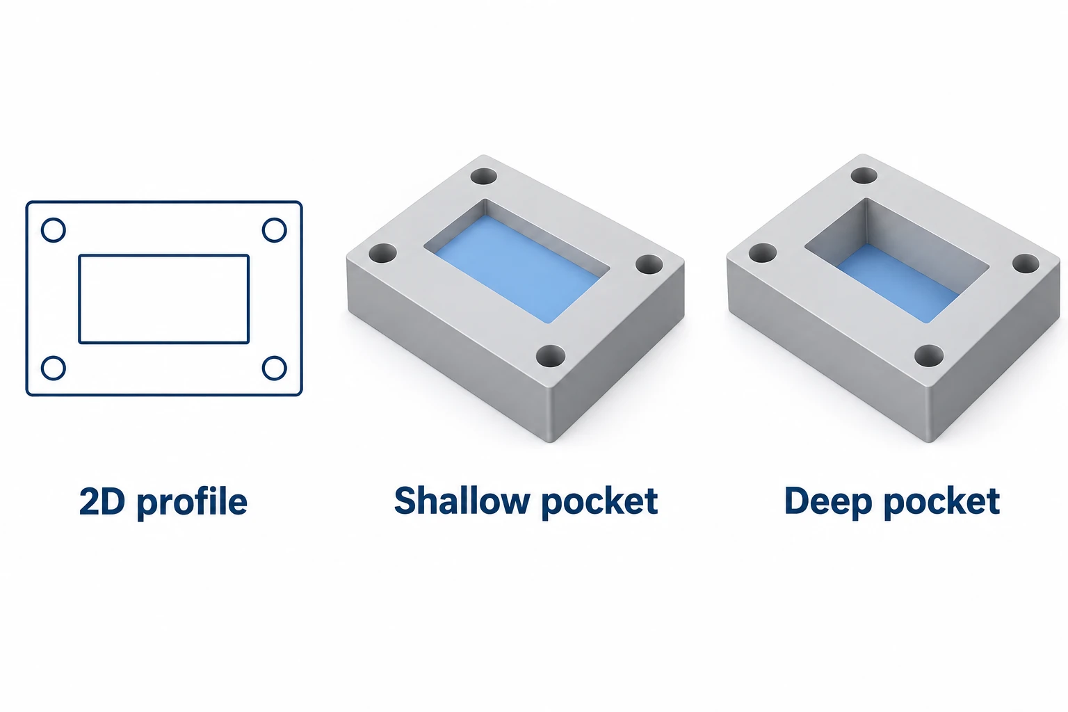
A top-view outline cannot resolve the two pockets above. Add the relevant thickness, depth and feature requirements through a dimensioned drawing or suitable 3D model. For questions about the geometry itself—such as corner access or usable thread depth—see the materials and part-design guide.
Reopen the export before handing it over
Open the file you will send, preferably in the receiving application or an independent compatible viewer. Compare it with the released design:
- Measure a known size. Confirm the imported units and overall dimension. STL is unitless; assigning inches to coordinates intended as millimeters makes the model 25.4 times too large. Correct the unit interpretation, not the approved design. [7]
- Count the intended parts and bodies. Check that the right configuration was exported and no required component or referenced file is missing.
- Inspect geometry. Review bores, pockets and small features. Use available import diagnostics for missing faces, gaps or invalid bodies; an attractive shaded view is not a geometry check.
- Check required information. Verify any PMI and associated drawing against the same revision. Resolve translation losses before release.

Keep the approved export with its matching requirements. The CNC machining RFQ guide covers the quantities, records and delivery scope to accompany those files. Our CNC machining service overview explains the available process routes.
Questions about CNC file formats
Are .stp and .step different types of geometry?
No. They are alternative STEP filename extensions. Inspect the actual file content and supported application protocol; the extension does not establish which geometry or annotations were exported.
Should I send every available format?
Send the agreed geometry file and required documentation. Add an alternative format when it solves a compatibility problem, clearly identifying it as the same revision. Several uncontrolled exports can make it harder to identify the intended definition.
Will exporting a finer STL solve a fit problem?
It may reduce geometric approximation error, but it does not define the fit limits or prove the final machined result. Use the original solid where available and specify the functional requirements separately.
Technical sources
- NIST — STEP File Analyzer and Viewer; geometry exchange, PMI and validation.
- Onshape Help — Supported File Formats; supported representations, native formats and version limits.
- SOLIDWORKS 2025 Help — Setting IGES Export Options; curves, trimmed surfaces and solid B-rep.
- Library of Congress — STL File Format Family; triangular surface representation.
- Autodesk Support — Mesh bodies are not recognized for toolpath generation in Fusion CAM after update; mesh manufacturing workflow.
- Autodesk Fusion Help — Convert a mesh body to a solid body; faceted and prismatic conversion.
- Autodesk Support — How to insert a mesh body into Fusion; unit interpretation.
- Autodesk Fusion Help — Export to DXF; drawing-sheet export. PTC Creo Help — Importing DXF or DWG Files with 3D Solids and 2D Entities as Drawings.



