On this page
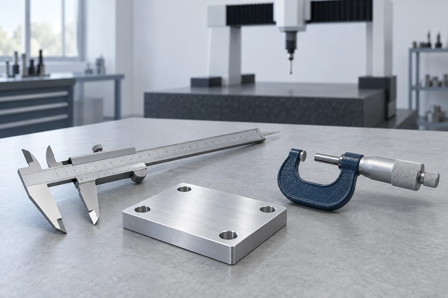
Calipers, micrometers and coordinate measuring machines answer different inspection questions. Calipers cover many accessible dimensions; micrometers suit defined contact measurements such as shaft diameter or thickness; a coordinate measuring machine (CMM) can evaluate feature locations and geometric relationships. The right choice depends on the characteristic, access and measurement uncertainty—not the instrument’s price or number of display digits.
CNC quality control connects that choice to the production sequence. A first-part check establishes the setup result, intermediate checks detect change, and final inspection verifies the required finished condition. Each stage needs a defined feature, method and response to an unexpected result.
Define the feature before choosing the instrument
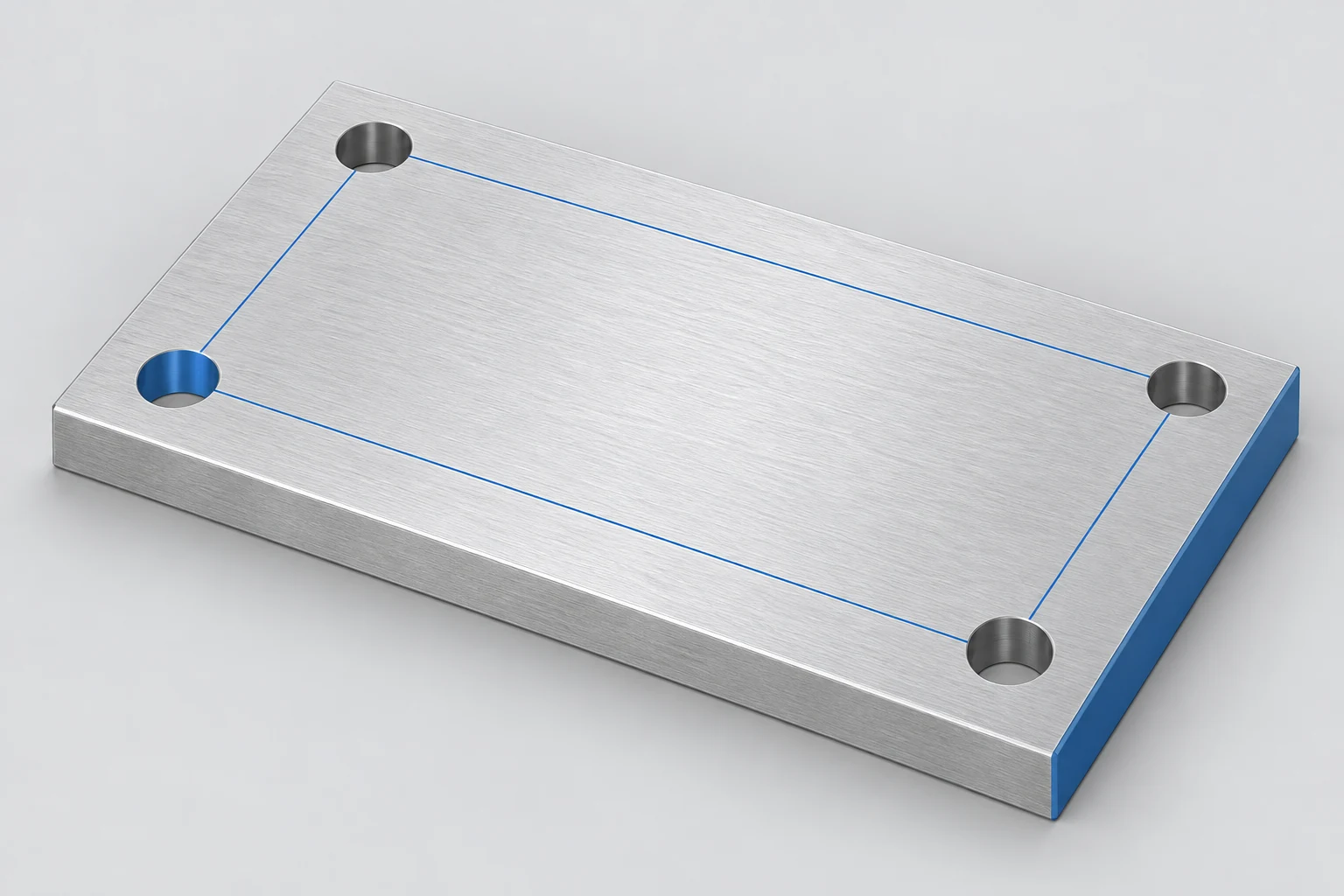
Take a mounting plate with four holes. Its outside length, hole diameters and hole-pattern position are separate questions. A reading across the plate cannot establish hole location. Likewise, a diameter reading does not fully describe a bore’s shape along its depth.
Begin with the released drawing: identify the characteristic, limits, units, datum references and condition in which the requirement applies. For the broader drawing-to-production sequence, the CNC machining basics guide provides the context.
Then ask whether the method can reach the specified surfaces and distinguish acceptable variation from measurement variation. Resolution is the smallest indicated increment. Accuracy concerns closeness to the true value; measurement uncertainty characterizes the doubt associated with a result. A fine readout alone establishes neither accuracy nor sufficiently small uncertainty. The assessment includes significant contributions from the instrument, operator, setup and environment. [1]
Calipers: versatile checks with contact limits
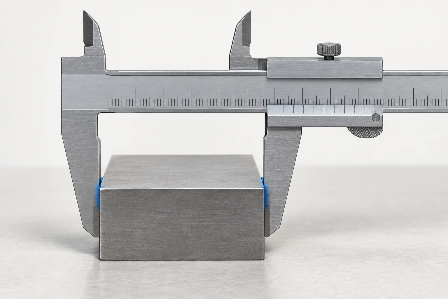
A suitable caliper can measure outside dimensions, accessible inside dimensions, steps and depths using its corresponding measuring faces. Its versatility is useful when checking a plate’s overall envelope or a noncritical step. Whether it is adequate for acceptance still depends on the particular tolerance and measurement method.
For an outside measurement, clean the contact surfaces, check the zero and seat the jaws squarely against the intended faces. Excess force, tilted jaws or contact on a burr can change the reading. Keep the contact location consistent when comparing successive parts.
Inside jaws introduce a different contact geometry. Small holes, chamfers and restricted access can prevent them from representing the required bore section. A depth rod seated on an uneven edge can also reference the wrong surface. Mitutoyo’s caliper guidance treats these as distinct measurement tasks with their own precautions. [2]
If a bore controls a fit, choose a method that reaches its specified depth and suits the tolerance—such as an appropriate bore gage, internal micrometer or CMM strategy. Do not approve the whole bore from a convenient reading at its mouth.
Micrometers: controlled contact for a defined dimension
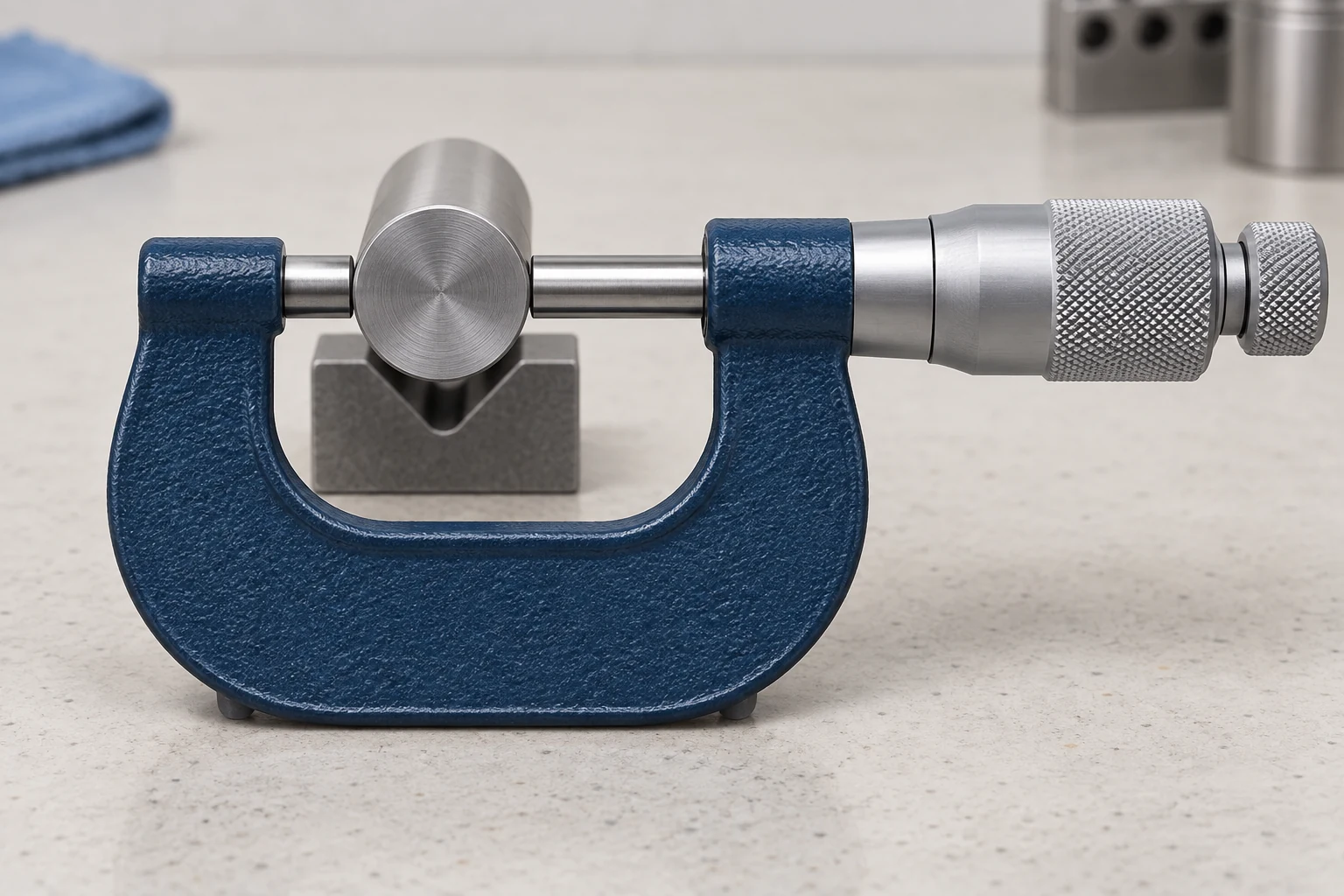
An outside micrometer places a feature between an anvil and spindle. With the correct range and measuring faces, it is useful for repeated shaft-diameter or thickness checks. A ratchet or friction mechanism helps control measuring force; use the instrument’s specified technique rather than tightening until the reading looks stable. [3]
On a shaft, align the measuring axis across the diameter. Measurements at several axial positions and orientations can reveal size variation that one reading misses. Those readings do not constitute a complete roundness or cylindricity evaluation. A groove, narrow land or curved surface may require different measuring faces.
Thin walls and compliant materials need particular attention to contact force and support. A repeatable reading on a squeezed feature may not describe its released size. Also identify the material and treatment stage: a finished, coated interface is a different measurement condition from the surface before coating. The materials and design guide connects those choices with the part’s functional requirements.
CMMs: feature relationships require a measurement strategy
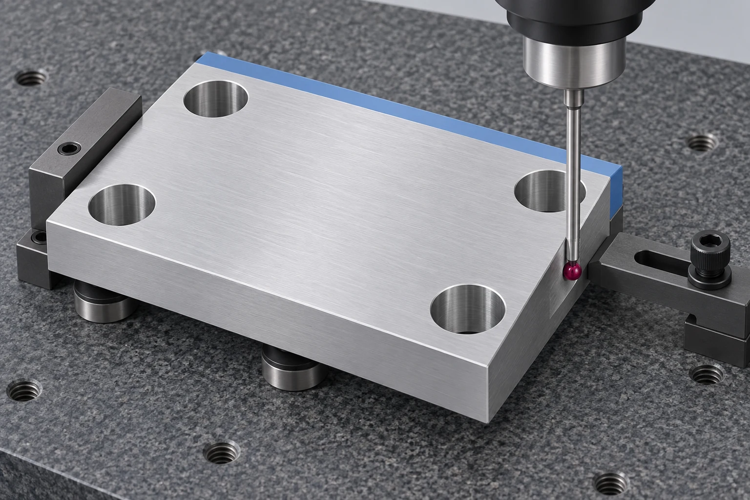
A CMM records points and evaluates features from them. It is useful when a hole pattern must be related to drawing datums, or when several surfaces must be evaluated in one coordinate system. More points can improve coverage, but their placement and the evaluation method matter.
Establish the reference system from the drawing’s datum requirements. Do not substitute the largest or easiest face merely because it simplifies loading. The plan must also address probe qualification, stylus access, part support and the locations sampled. Sparse points can miss local form variation, while excessive clamping can distort a flexible part. ZEISS’s guidance on CMM inspection errors discusses these sources of variation. [4]
A standard dimensional CMM inspection does not automatically include surface roughness. That requirement needs a suitable texture-measurement method. Nor does a CMM label settle a close-tolerance size dispute: the actual measurement strategy and uncertainty must support the decision.
Turn a mounting plate drawing into an inspection plan
The following example assigns inspection work for a four-hole mounting plate. It is a planning framework: the released drawing supplies the limits, datums and applicable condition. The method still needs to be qualified for each requirement.
| Characteristic | Candidate method | Define before measuring | What this check leaves open |
|---|---|---|---|
| Overall length and width | Caliper, if adequate | Opposing faces; jaw seating; contact positions | Hole location and surface form |
| Plate thickness | Suitable micrometer | Accessible points; contact force; free or restrained condition | Flatness across the plate |
| Hole diameter | Bore gage, internal micrometer or CMM | Depths; orientations; setting or probing method | Unsampled form and hole position |
| Hole-pattern position | Suitable CMM program | Drawing datums; feature sampling; evaluation settings | Material, finish and unreported characteristics |
| Seating-face flatness | Suitable form or CMM method | Support; surface coverage; evaluation | Surface roughness |
Add the inspection stage, frequency and record required for each row. A useful plan names the characteristic that an instrument verifies; an equipment list alone does not do that. VETCNC’s precision CNC machining service is the related service for a drawing-specific discussion of the manufacturing and inspection scope.
Connect first-part, in-process and final checks
First-part checks evaluate the setup’s output before further production. They should cover characteristics affected by that setup, including relationships created across operations. A tool change, offset adjustment or reloading event may require relevant checks again.
In-process checks follow characteristics that can change as cutting continues. A drifting shaft diameter, for example, may call for investigating tool wear or temperature before adjusting an offset. Renishaw’s process-control framework distinguishes setup controls, active monitoring during machining and checks after machining. [5]
Final checks assess the specified delivery condition, including relevant effects of subsequent treatment. Define inspection coverage by characteristic and risk. NIST describes acceptance sampling as a way to decide the disposition of a lot; it does not establish conformity of every unmeasured part. [6]
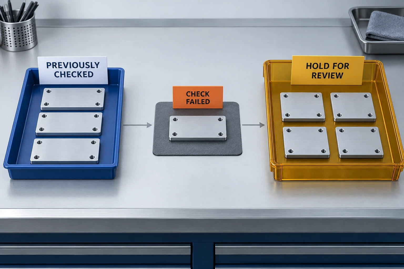
If a check fails, identify and segregate the potentially affected material while investigating the cause. The suspect interval can extend back before the failed check; the last recorded acceptable result is evidence for that investigation, not automatic clearance for everything made afterward.
When two instruments disagree, compare the methods
Do not average conflicting readings or assume the CMM must be right. Work through the difference:
- Confirm the same quantity. Compare the feature, units, drawing revision, section, orientation and treatment stage. A local two-point diameter and a fitted diameter from sampled coordinates may differ.
- Check the physical setup. Look for contamination, burr contact, temperature differences, misalignment, restraint and measuring force.
- Check the measurement system. Review instrument condition, calibration information, setting references and the CMM program or probe qualification.
- Resolve the acceptance basis. Use the qualified method and agreed decision rule. For readings near a limit, that rule determines how measurement uncertainty enters the conformity decision. [7]
Record enough to reconstruct the decision
Record the part and revision, characteristic, requirement, result with units, method or program, measurement stage, inspection coverage and disposition. Include relevant setup conditions and the acceptance basis where needed. The CNC machining RFQ checklist helps carry those deliverables into the order, so the report answers the agreed inspection questions.
CNC inspection FAQ
Does every CNC part need CMM inspection?
No. Use methods that can verify the specified characteristics with suitable uncertainty. An accessible shaft diameter may suit a micrometer; a datum-related hole pattern may justify a CMM or suitable dedicated gaging. Define coverage separately from the instrument choice.
Is a calibration sticker enough to prove a measurement is reliable?
No. The calibration information must be relevant to the instrument and task, and the measurement procedure still matters. NIST defines traceability through a documented calibration chain with uncertainty contributions; traceability alone does not establish fitness for a particular measurement. [8]
Can an on-machine probe replace final inspection?
Only where its method and coverage are suitable for the specified acceptance requirements. A probe used to set offsets or monitor a feature does not automatically verify every finished characteristic. Checks after later treatment may still be needed.
What should “100% inspection” mean on an order?
Define which characteristics are checked on every part, by which methods and at which stage. The phrase alone does not identify the features covered, establish measurement reliability or replace a clear acceptance rule.
Technical sources
- NIST. Essentials of Expressing Measurement Uncertainty: Basic Definitions. Significant contributors to the measurement process.
- Mitutoyo. General Catalog, Section D: Calipers—Quick Guide to Precision Measuring Instruments. Contact geometry and measurement precautions.
- Mitutoyo. General Catalog, Section B: Micrometers. Measuring faces, applications and constant-force devices.
- ZEISS. Common CMM Inspection Errors and How to Reduce Them. Alignment, probing, support and measurement conditions.
- Renishaw. Transform Your Manufacturing, Productive Process Pyramid. Setup, in-process control and post-process monitoring.
- NIST/SEMATECH. Engineering Statistics Handbook, 6.2.1: What Is Acceptance Sampling?
- Mitutoyo. Decision Rules, TAR, and TUR, EDU-15005A. Decision rules and measurement uncertainty; apply the requirements agreed for the task.
- NIST. Metrological Traceability: Frequently Asked Questions and NIST Policy, §3.2.



