On this page
Climb milling is usually the first choice on a rigid CNC setup that controls backlash. [4] Its thick-to-thin chip formation reduces rubbing at entry. Conventional milling remains useful when a difficult surface layer or the machine setup changes the cutting conditions. Neither direction guarantees a good finish by itself. [3]
The distinction concerns how a cutting edge meets the material. It does not describe a different machine or a separate manufacturing process. For the wider sequence of cutters, setups and toolpaths, see how CNC milling works.
Identify the feed direction at the cutting edge
Climb milling is also called down milling; conventional milling is also called up milling. To identify them, imagine the cutter center staying still while the workpiece feeds past it. Compare that workpiece motion with the tangential motion of the cutting edge where it contacts the material. [1]
- Climb: the workpiece feeds in the same direction as the edge motion at contact.
- Conventional: the workpiece feeds against the edge motion at contact.
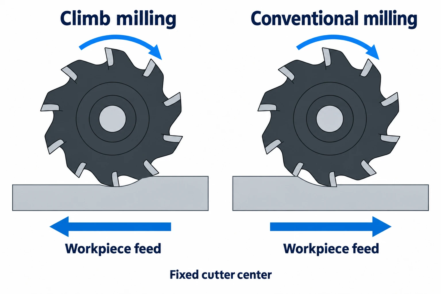
A CAM screen usually shows the cutter center moving relative to a stationary part. That feed arrow is opposite to the workpiece-feed convention above. State which object moves before comparing diagrams. “Clockwise” alone describes rotation or travel around a contour; it does not identify climb milling without the contact side.
Chip formation changes rubbing and surface finish
| Peripheral cutting behavior | Climb milling | Conventional milling |
|---|---|---|
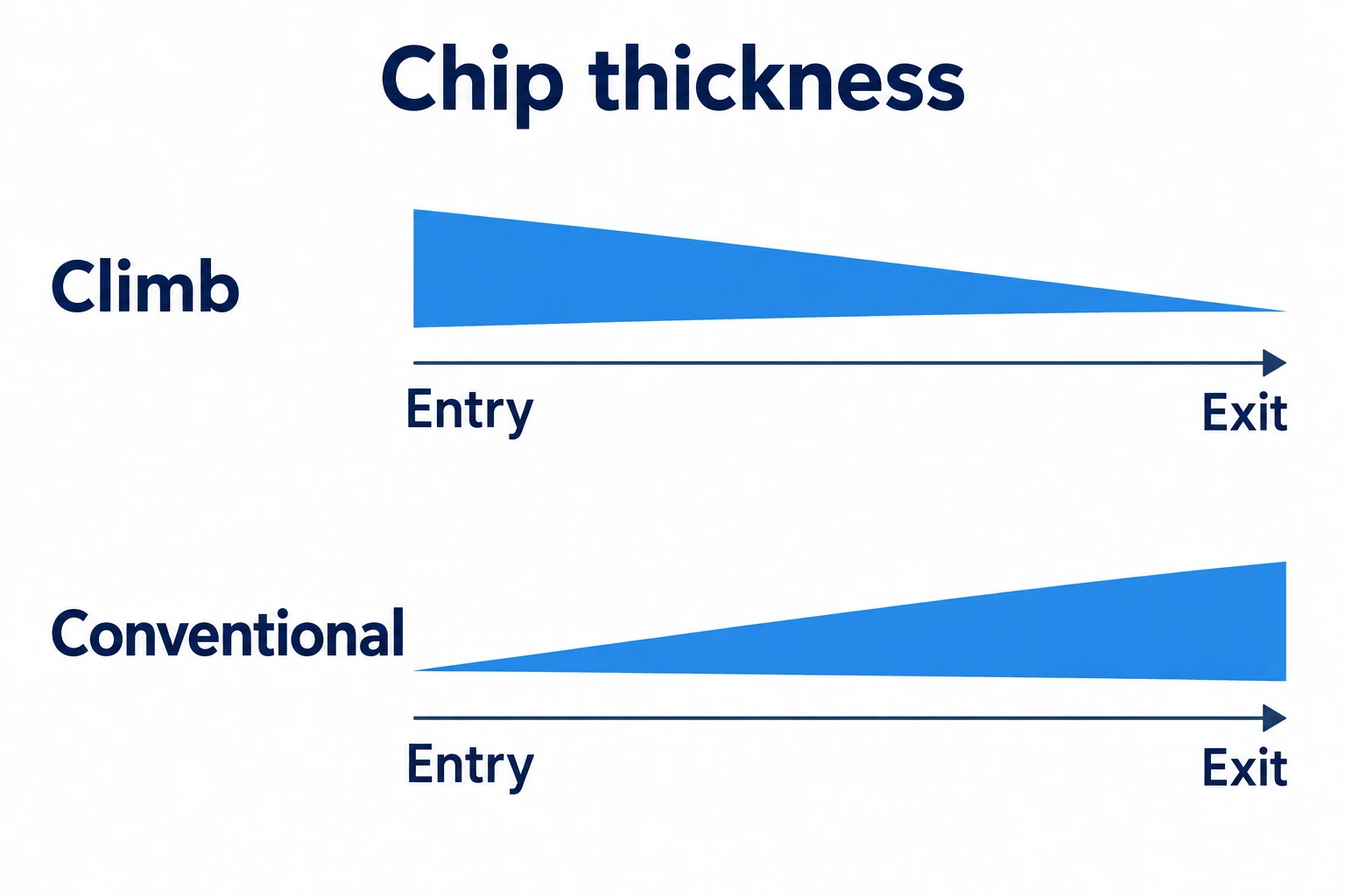
| Uncut chip thickness through engagement | Thicker at entry, thinning toward exit | Near zero at entry, increasing toward exit |
| Initial edge contact | Begins by taking a chip | More rubbing before a chip develops |
These are peripheral-cutting tendencies, not guaranteed roughness values. Harvey Performance connects climb milling’s finish advantage with reduced rubbing and chip recutting. [3] The progression describes uncut chip thickness, not the final shape or length of a curled chip.
Tool load also depends on how much edge is engaged. A light side-finishing pass and a full-width slot are different load cases even at the same feed setting. Long overhang, cutter deflection and retained chips can spoil the result before changing direction offers any benefit. [6]
Choose by the machine, stock and tool
Backlash is lost motion in the feed mechanism. Climb cutting can pull the work into the cutter, taking up that play abruptly and increasing the actual bite. Conventional milling does not repair the mechanism; it changes how the cutting load acts against the feed. [2]
| Condition | Direction to consider | Reason or limit |
|---|---|---|
| Rigid setup with controlled backlash | Climb as the starting choice | Favorable entry and chip formation |
| Uncontrolled feed play | Conventional, following the machine’s operating guidance | Avoid assuming the table can resist a climb cut’s pulling action |
| Hard or rough surface layer | Conventional may help | Assess entry below the difficult layer; do not classify every casting alike |
| Large variation in stock allowance | Evaluate conventional | Entry loading changes with the remaining stock |
| Ceramic inserts in a heat-resistant alloy | Follow application guidance; up milling may be specified | Impact sensitivity changes the usual preference |
The backlash, allowance and ceramic-tool distinctions follow Sandvik’s application guidance. [2] Harvey’s surface-layer discussion concerns the entry condition, rather than a rule that all cast or forged parts need conventional milling. [3] Machine condition matters more than simply labeling a mill “manual” or “CNC”; the manual versus CNC comparison covers that broader distinction.
Pockets, islands and slots change the contact side
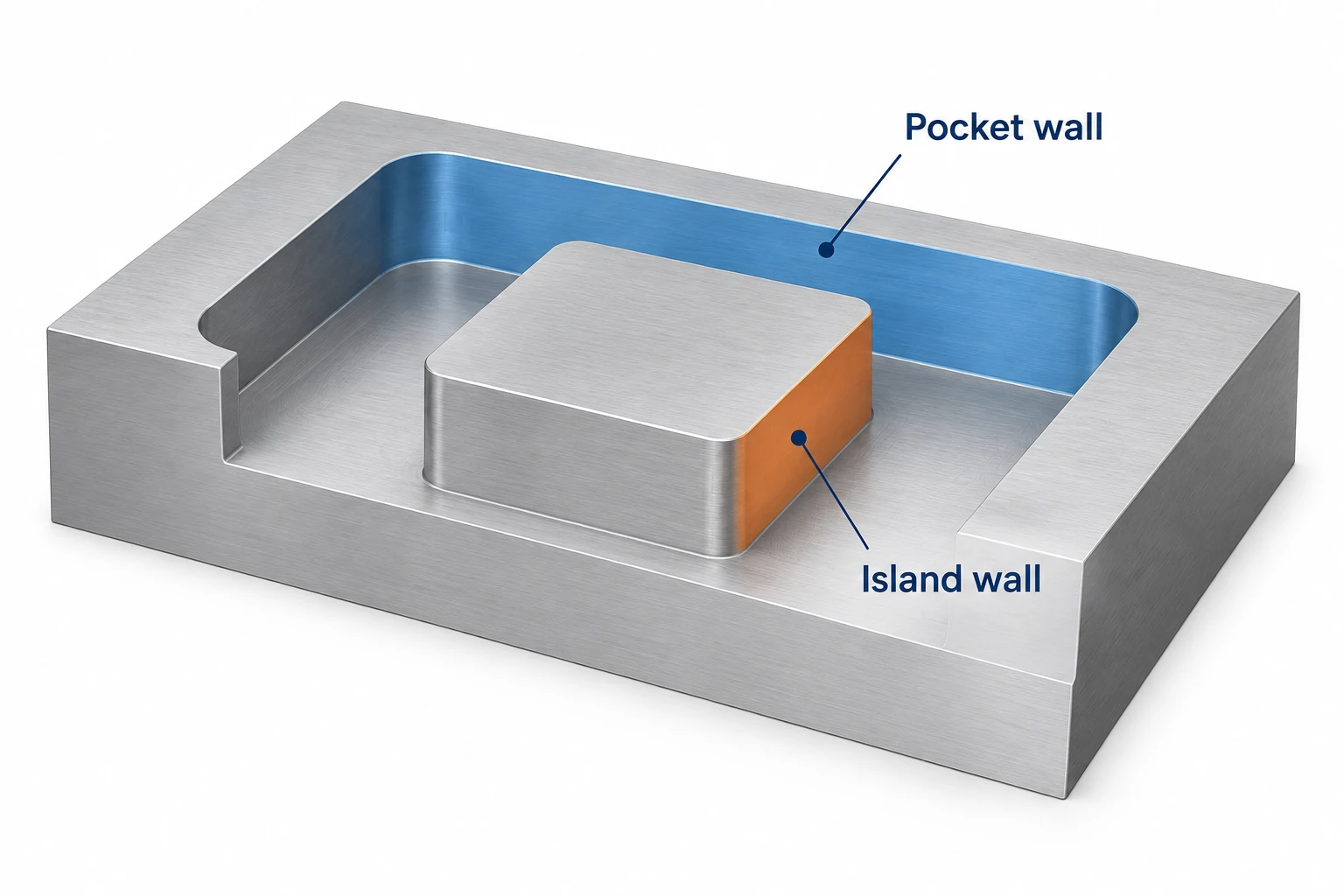
For a right-hand cutter rotating clockwise when viewed from above, a climb-finishing path runs counterclockwise around an internal pocket boundary and clockwise around an external island. The cutter contacts opposite sides of those boundaries. Haas’s programming workbook illustrates this reversal between pocket and island paths. [4]
A full-width slot engages the cutter on both sides, so it cannot be treated as a single side-wall climb pass. For an accurate slot, roughing with an undersized cutter and finishing the walls separately allows better control of engagement. Sandvik’s keyway guidance even recommends up-milling for its finishing approach—an important exception to “climb always gives the best result.” [6]
Check the generated path, not only the CAM option’s name. Autodesk Fusion’s Direction setting attempts to maintain the chosen mode, but geometry can prevent it throughout the path. Its Both Ways option deliberately includes climb and conventional passes on open profiles, with separate settings for the reverse pass. [5]
Compare the finished feature, not just the sound of the cut
When evaluating a direction change, record the material, tool, reach, radial engagement, axial depth and feed conditions. Keep the comparison consistent where practical, and note any other changes needed for a viable cut. Otherwise, an apparent improvement cannot be attributed to direction alone.
Inspect surface texture, feature size and wall form separately. A smoother wall can still be tapered or out of size. At an internal corner, check whether engagement rises sharply: Autodesk identifies tight corner geometry as a cause of chatter and distorted finish. Changing the direction label will not remove that geometry. [5]
For a part being outsourced, specify the required dimensions and surfaces. The supplier can choose a suitable cutting route unless the drawing or approved process requires a particular one. Our CNC milling services page covers the component features and inspection scope used in that discussion.
Questions about climb and conventional milling
Is climb milling always better for thin walls?
No. Secure support and the workpiece’s ability to withstand the cutting forces still matter. Direction alone is not a thin-wall machining strategy. [1]
Does “down milling” mean the tool feeds downward in Z?
No. Down milling is another name for climb milling. It describes the relation between cutting-edge motion and feed at engagement, not a plunge into the workpiece. [1]
Sources
- MIT OpenCourseWare, Introduction to the Mill, 2004, PDF page 5: workpiece-feed definitions. Its manual-shop recommendations are not a universal CNC cutting rule.
- Sandvik Coromant, Down Milling vs. Up Milling: peripheral chip formation, backlash, varying allowance and ceramic-insert exceptions.
- Harvey Performance Company, Climb Milling vs. Conventional Milling: rubbing, chip recutting and difficult surface layers.
- Haas Automation, Mill Programming Workbook, printed pages 61 and 112: cutting direction and pocket/island boundaries. Referenced for geometry, not current control commands.
- Autodesk Fusion, 2D Adaptive Roughing Reference: Direction, Both Ways and Minimum Cutting Radius.
- Sandvik Coromant, Groove or Slot Milling: end-milling load, deflection and separate keyway-finishing passes.



