On this page
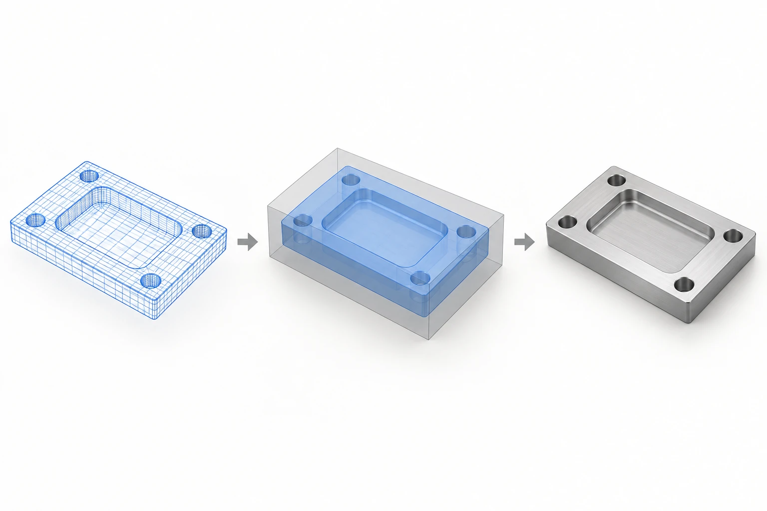
A CAD file defines the part to be made. In a CAD/CAM workflow, that definition must become a workable sequence of setups, tools and machine instructions before machining starts. The shop checks the received geometry and requirements, plans how to hold and reach the part, generates toolpaths, verifies them and prepares a program for the intended machine.
For an engineer or buyer, the useful question is what remains undecided after the model opens successfully. A pocket may be visible in CAD while its tolerance, cutting access or inspection requirement still needs clarification. The following steps explain that gap within the broader CNC machining workflow.
Establish which part definition will be manufactured
The received file needs a geometry check: units, overall size, missing faces, intended bodies and revision. A recognizable shape alone does not prove a successful transfer. Comparing a known overall dimension is a useful way to catch a scale error before programming.
Then the geometry must be read with its manufacturing requirements. Material and condition, threads, tolerances, surface requirements and inspection criteria may be supplied through a drawing, model annotations or an agreed combination. NIST’s work on model-based definition emphasizes retaining the information needed by manufacturing and inspection when moving from drawings to models.[1]
If a drawing and model disagree, identify the conflict and resolve which definition governs. Do not silently select the easier dimension. A nominally unchanged shape can also acquire a tighter tolerance or different finish requirement, so revision checking includes the requirements as well as the solid.
Add the stock, holding method and machining references
CAM preparation describes the starting condition around the finished part. The programmer defines stock, machining orientation, a coordinate origin and the relevant fixture geometry. These are separate from the finished CAD model. Autodesk’s setup documentation distinguishes the model, work coordinate system and fixture for this reason.[2]
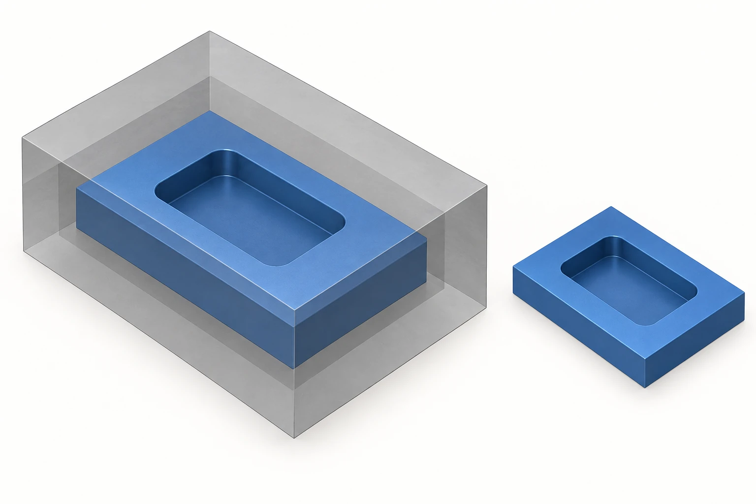
Consider a pocketed plate that also needs machining on its underside. The first setup must hold the plate while leaving the pocket accessible. The second needs a way to locate and support the partly machined piece. Removing every convenient gripping surface in the first operation can make the next operation harder to control.
The machining origin is a programming reference. It must correspond to a reference that can be established on the actual setup; it is not automatically the same as the designer’s model origin or a drawing datum. The choice of machining processes and setup sequence therefore happens before the file becomes executable instructions.
Why the manufacturing model may look different
The programmer may create a manufacturing model alongside the original design. This can include workholding geometry or additional surfaces used to calculate a particular operation. Those additions describe how the part will be made; they do not necessarily revise what the customer ordered.
For example, a virtual surface patch can cover a hole or pocket so a selected surface-machining path does not dip into that opening. Autodesk documents this technique in a manufacturing-model example while leaving the original design data unchanged. The relevant operation must actually include the added surfaces in its calculation; merely displaying them is insufficient.[7]
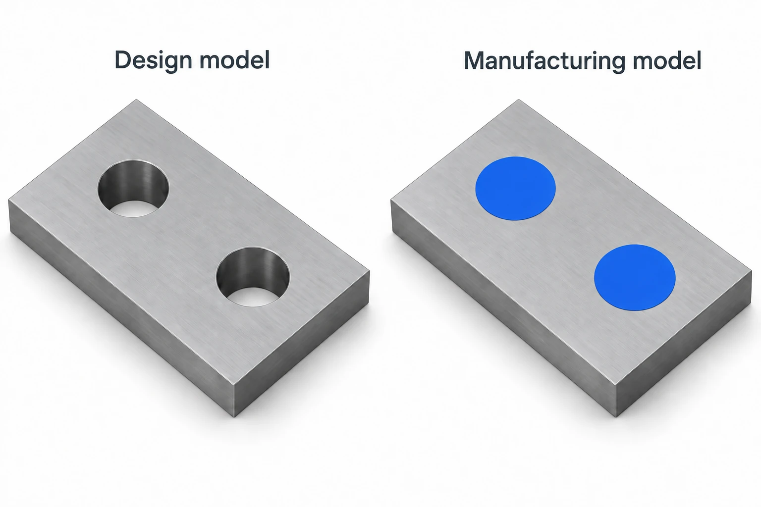
This distinction matters when reviewing a CAM screenshot. A covered opening may be a programming aid rather than a deleted feature. Ask whether the displayed model represents the finished part or an intermediate manufacturing operation. Any proposed change to the finished geometry still needs resolution against the agreed part definition.
Turn each feature into suitable operations
A pocket does not specify its own cutter, entry move, roughing passes or finishing strategy. Those choices depend on the material, available tooling, accessible geometry, remaining stock and required result. CAM software calculates paths from these choices; it does not remove responsibility for making them.
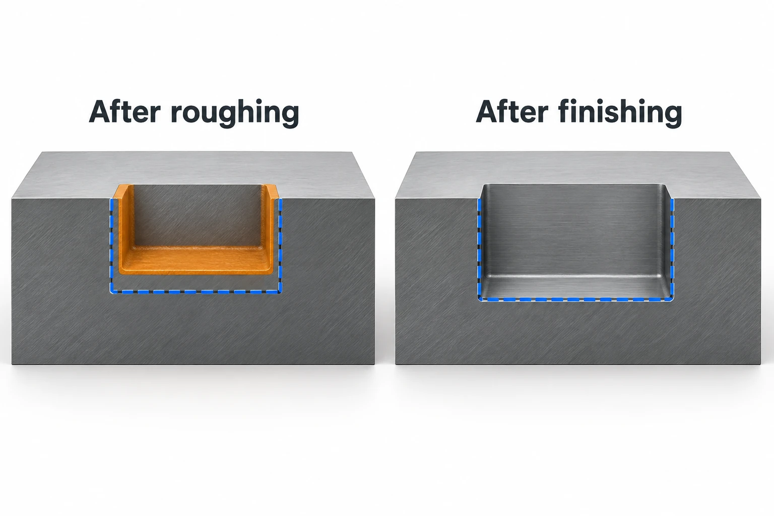
For the plate example, a larger cutter may remove most of the pocket material, with a smaller cutter reaching the remaining corners. Roughing can deliberately retain material on the walls and floor for later passes. That stock allowance belongs to the manufacturing plan; it does not change the finished dimensions on the drawing.[3]
The plan also accounts for operations that the model does not describe by shape alone, such as the required thread specification or a finishing requirement on a mating face. The explanation of cutters, toolpaths and milled features covers how those cutting actions differ.
If the intended approach cannot reach a feature, the next step is a specific engineering question. For the pocketed plate, that might be whether a larger internal radius is acceptable or whether the geometry must remain unchanged and require another approach. The designer supplies the functional constraint; the shop evaluates the manufacturing options. A useful answer identifies the affected feature and its purpose, rather than giving blanket permission to alter the model for easier machining.
Check more than the tool tip
Simulation can reveal uncut stock, unwanted contact and problematic moves, but its scope matters. A check containing only the cutter and stock does not represent every possible machine or fixture interference. Autodesk distinguishes simulation with machine kinematics from simpler tool-and-stock simulation.[4]
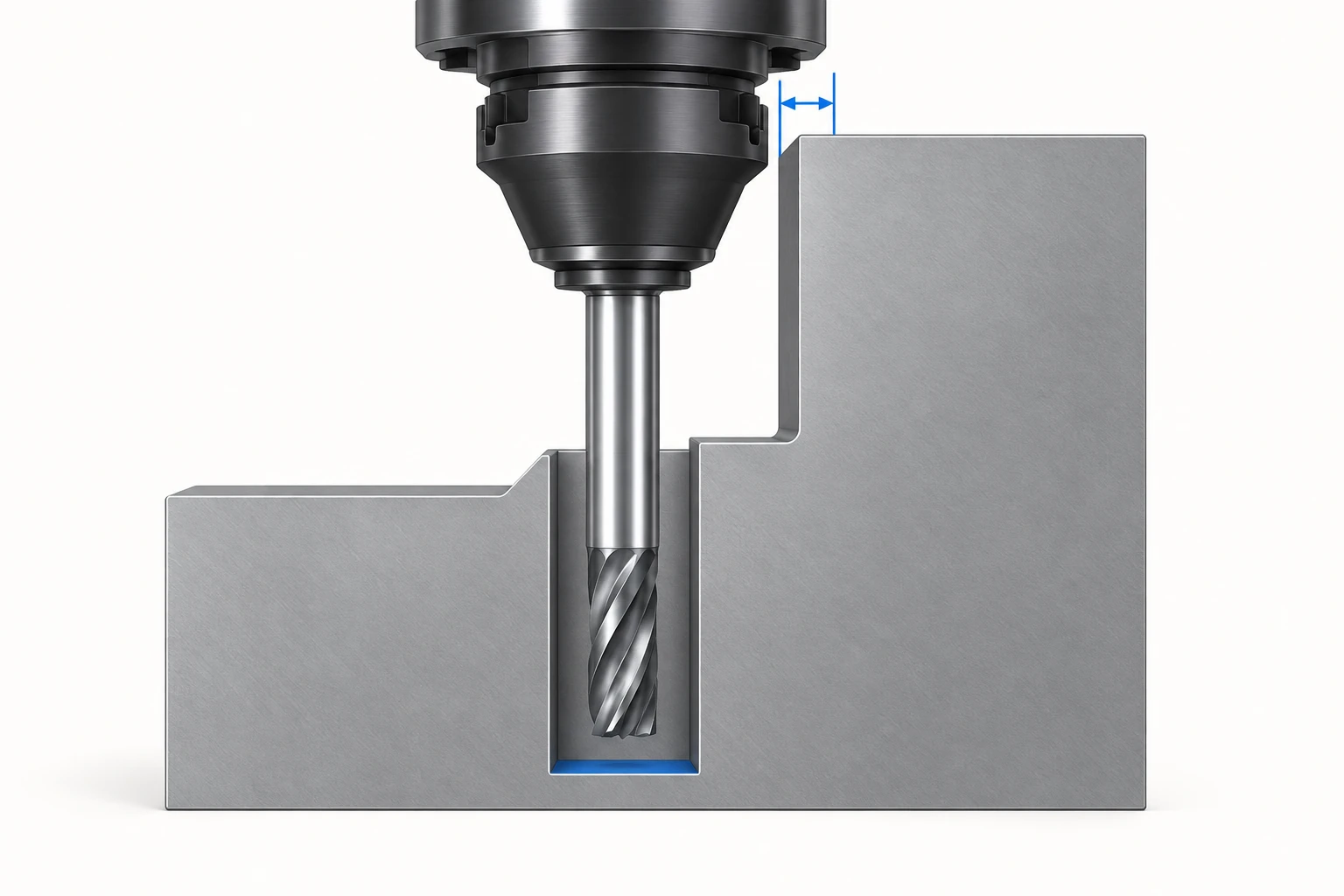
Include the geometry relevant to the intended check: cutter, shaft, holder, stock, fixtures and, where supported, the machine. Review approach, withdrawal and moves between cuts as well as the cutting passes. A fixture omitted from the model cannot contribute its actual shape to a collision check.
Simulation verifies a modeled process. It does not by itself establish the actual offsets, clamping condition or dimensional acceptance of the finished part. A clean result is useful evidence about the programmed motion within the modeled conditions.
Prepare the program and match it to the physical setup
Postprocessing converts CAM toolpath data into instructions formatted for the selected machine and control. Texas A&M’s hosted Autodesk CAM teaching material separates this step from generating and verifying the paths.[5] The postprocessor and its configuration must suit the intended machine.
At the machine, the physical stock, holding arrangement, tools and offsets must match the preparation. Work offsets establish the workpiece reference; tool offsets account for the relevant tool geometry. Haas documents these as distinct parts of mill setup.[6] Simply opening a CAD file or loading a program does not establish them.
The operator also needs enough information to reproduce the intended setup. A CAM setup sheet can include a model view, stock orientation and size, work coordinate information, tools and operation details. Autodesk lists these as outputs of its setup-sheet function.[8] The sheet makes choices made during programming visible to the person preparing the machine.
For the plate’s second setup, a useful handoff makes clear which face is now presented for machining and how the partly machined part is oriented. A program name alone cannot communicate that relationship. Program output, setup information and part revision need to agree; otherwise, a correctly generated program can still be paired with the wrong preparation. This is why completing CAM calculations and preparing the machine are separate milestones.
Inspection requirements also belong in this preparation. If acceptance depends on the relationship between features cut in different setups, checking each feature’s size separately may not answer the drawing requirement. Identify the characteristic to verify, the applicable reference and when it can be checked. This connects the manufacturing sequence to the agreed acceptance criteria without assuming that a simulated toolpath proves the finished relationship.[1]
A small revision can affect several preparation steps
A revised file should identify what changed and replace the superseded definition explicitly. CAM associations can help update affected paths, but changes still need review, verification and fresh machine output where applicable. Existing released code does not become current merely because a new model arrived.[5]
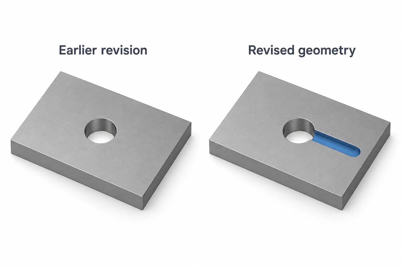
Different revisions affect different parts of the preparation:
- Deeper pocket: revisit tool reach, holder clearance, stock removal and remaining wall or floor geometry.
- Added underside feature: revisit additional access, second-setup location and available gripping surfaces.
- Same geometry, tighter tolerance: revisit the finishing method and inspection plan, even if the nominal toolpath can be reused.
- Different material condition: revisit tool selection and cutting parameters, along with the relevant finishing or treatment sequence.
What can be reused on a repeat order?
A repeat part does not necessarily require every programming choice to be made again. A retained CAM project, established operation sequence or suitable operation template can provide a starting point. Autodesk’s template library, for example, creates operations in the active setup from saved templates.[9] Reuse preserves useful work; it still requires checking that the current job matches the conditions behind that work.
Start with the released revision and manufacturing requirements, then compare the stock, material condition, intended machine, tools and holding arrangement. If these remain applicable, much of the existing plan may carry forward. If the plate now arrives as thicker stock, however, the stock definition and affected removal operations deserve review even when the finished CAD shape is identical. A machine change can also affect the required program output and setup assumptions.
Changes do not always invalidate the entire project. The practical task is to identify affected operations and their dependencies, regenerate where needed and verify the resulting process. In Fusion, a change can make an operation out of date, requiring regeneration.[10] That supports targeted updates, but a software status cannot confirm that unrecorded shop-floor conditions have stayed the same.
For a machining request, send a clearly identified revision with the requirements that determine acceptance. Flag unresolved conflicts and functional surfaces. Our CNC RFQ file checklist covers that handoff. The goal is a consistent definition from which the shop can prepare the process and check the resulting part.
Technical sources
- NIST, Promoting Model-Based Definition to Establish a Complete Product Definition (2016), abstract. Used for the information requirements of model-based definition.
- Autodesk Fusion Help, Setup tab (milling and cutting) reference. Model, fixture and work coordinate system definitions.
- Autodesk Fusion Help, Horizontal Roughing/Finishing reference, “Stock to Leave.” No software default is presented here as a universal machining allowance.
- Autodesk Fusion Help, Simulation for manufacturing. Scope of simulation with and without a machine model.
- Autodesk, CAM, teaching slides hosted by Texas A&M University, slides 10 and 15–19. Used for the general workflow and revision sequence, not current software interface instructions.
- Haas, Mill Operator’s Manual, Chapter 8: Part Setup, sections 8.3 and 8.5. Tool and work offsets; specific machine procedures follow the applicable manual.
- Autodesk Fusion Help, Example: Add work-holding equipment and patch a surface, “Patch surfaces for toolpath generation.” Manufacturing-model changes and the unchanged design definition.
- Autodesk Fusion Help, Setup sheets. Operator documentation generated from the machining setup.
- Autodesk Fusion Help, Manage the Template Library. Creating operations from saved templates.
- Autodesk Fusion Help, Generating operations in the Manufacture workspace. Regeneration of affected operations.