On this page
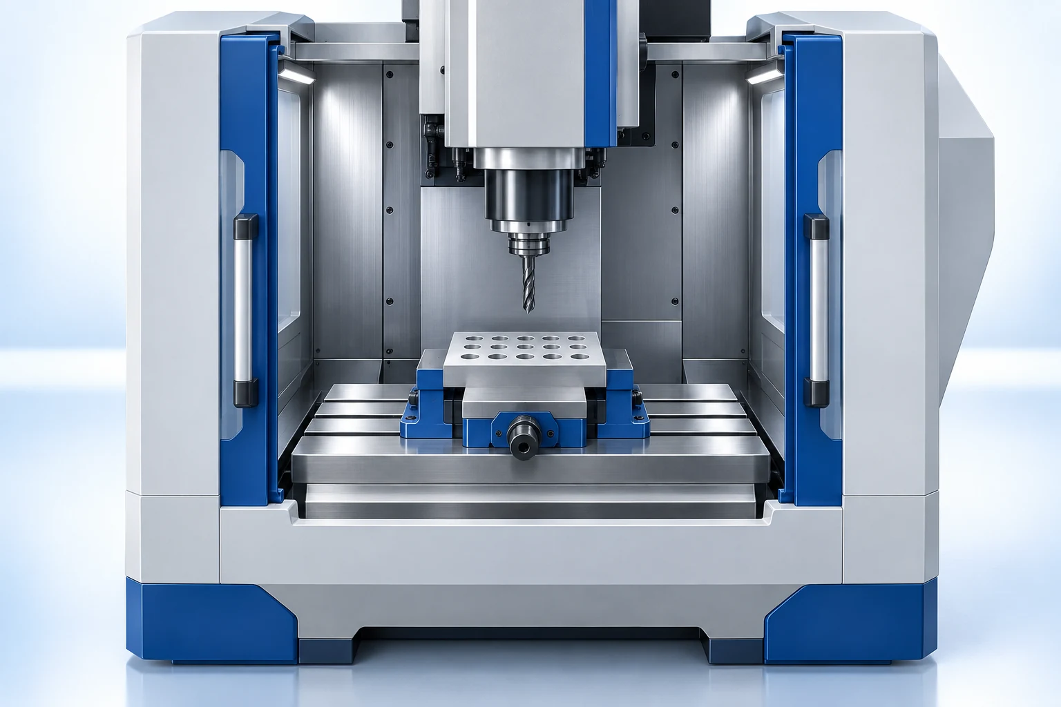
A CNC drilling machine positions a tool and controls its feed to produce holes at programmed locations. Whether it can finish your part depends on more than the largest drill it accepts. Hole direction, tool access, chip removal, threading, finishing and inspection all affect the route.
For a mounting plate with many similar holes, a drill-tap center may offer an efficient sequence. A housing with side ports, deep passages and locating bores presents a different task—even if every hole diameter looks modest. Evaluate the complete hole pattern and its requirements before treating a machine name as proof of suitability.
Drilling machine, drill-tap center or machining center?
These labels describe overlapping equipment categories. A dedicated CNC drilling machine may be arranged around a particular workpiece or drilling task. A drill-tap center commonly combines programmed positioning, tool changes and threading functions. A general machining center can also drill and tap alongside milling.
The distinction is not “drilling only” versus “everything else.” Haas, for example, describes its DT-1 drill-tap machine as having full milling capabilities. Its specification separately lists spindle speed, tapping speed, travels, tool limits and spindle-to-table distances. Those separate entries matter more than a broad category label. [1]
For an outsourced part, the practical question is which operations can share a stable setup. Drilling clearance holes, finishing locating holes and tapping fastener holes may require different tools, yet remain in one clamping. Cutting a side port can require another orientation. Our guide to CNC machining centers explains the wider machine configurations; the focus here is how they serve a complete set of holes.
A tool changer helps execute that sequence, but does not establish the result. Tool assemblies must fit the spindle and magazine, and each tool needs a suitable approach. Count the required drilling, finishing, threading and inspection tools when evaluating a proposed setup, rather than counting hole diameters alone.
Match the spindle to the material and drill diameter. Use the tool supplier’s cutting recommendations for the specified alloy and condition to establish the required rpm, then check available torque and power at that speed. Small drills may need high rpm; larger drills can be limited by cutting load. Maximum rpm alone does not prove suitability, and a material change can alter the load without changing the hole pattern. [3]
Separate hole function from the operation name
Start with what the hole does in the assembly. A clearance hole allows a fastener to pass. A locating bore controls a mating feature. A threaded hole must provide the specified usable thread. A fluid passage introduces internal-edge and cleanliness questions. Similar openings can therefore require different manufacturing and acceptance plans.
| Hole function | Requirement to define | What the route must address |
|---|---|---|
| Fastener clearance | Diameter, position and edge condition | Drilling and accessible deburring |
| Locating pin or fitted bore | Size, geometry and datum relationship | Prepared hole, suitable finishing and measurement |
| Blind threaded attachment | Thread designation and full-thread depth | Drill depth, tap lead and bottom clearance |
| Counterbored mounting hole | Recess diameter, depth and seating surface | Tool sequence and concentric feature relationship |
| Intersecting passage | Intersection, internal burrs and cleanliness | Interrupted cutting, edge access and inspection |
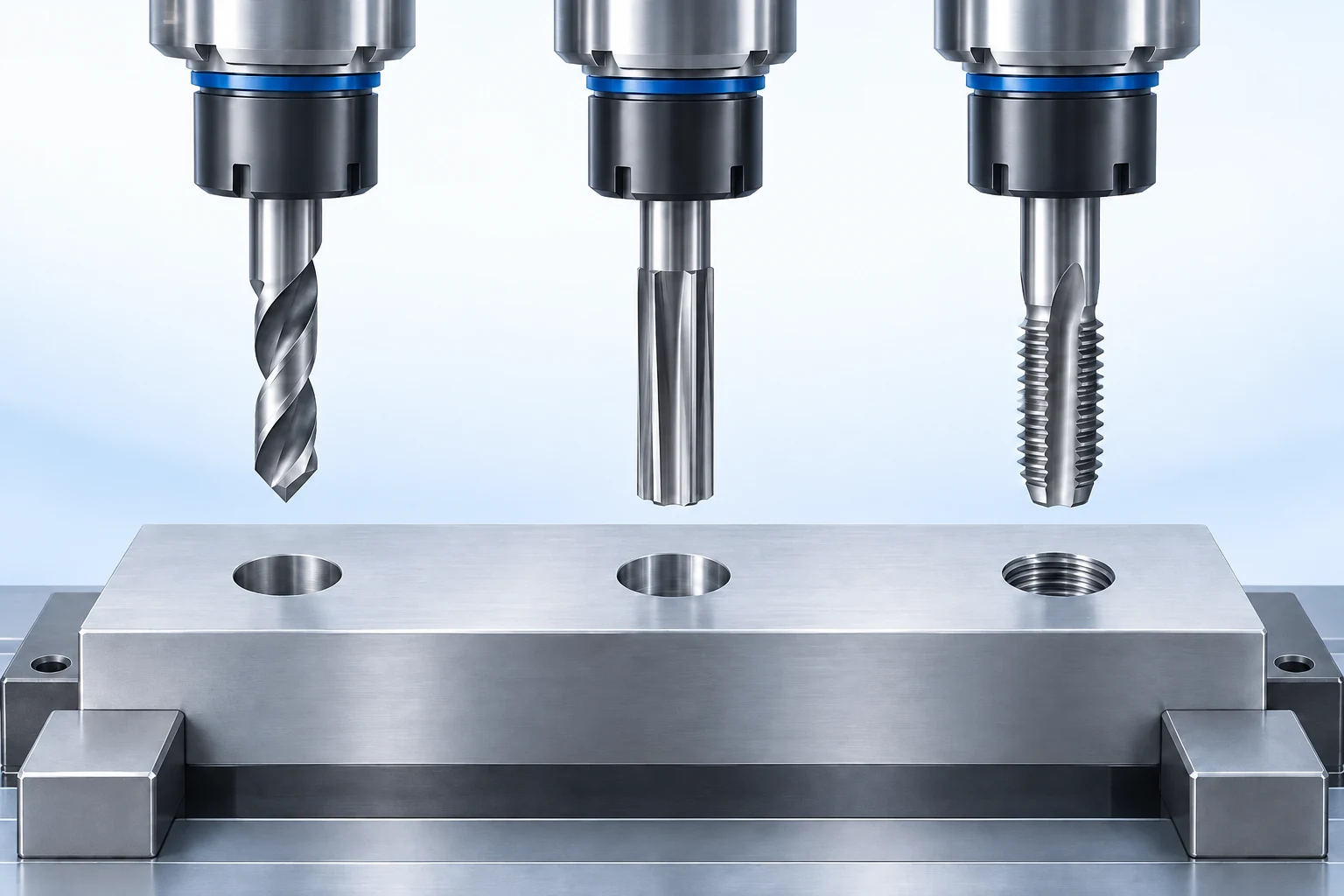
A supplier’s statement that a hole will be “drilled and reamed” describes a route, not an acceptance limit. Reaming finishes a prepared hole; its stock allowance, alignment, toolholding and clamping affect the result. Too little or too much material left for the reamer can undermine the operation. [2]
Keep the drawing requirements in charge. Read individual dimensions together with general tolerances and referenced specifications. If the part needs a controlled bore location, do not assume that adding a finishing tool automatically corrects an incorrectly located initial hole. Discuss how the complete process establishes and verifies that location.
Check the assembled setup, beyond the bare part
Machine travel is a movement range. It does not describe all the space available to a drill, holder, workpiece and fixture together. A plate may fit on the table while a long drill cannot retract above it, or while the holder approaches a clamp before the cutting edge reaches depth.
The DT-1 specification lists three distinct dimensions: [1]
| Published specification | Value | Dimension described |
|---|---|---|
| Z-axis travel | 394 mm | Movement range along the Z axis |
| Maximum spindle-nose-to-table distance | Approximately 546 mm | Separation between the spindle nose and table |
| Maximum tool length | 178 mm | Tool length measured from the gauge line |
These are three different dimensions, not three interchangeable hole-depth limits. They describe that machine configuration, not VETCNC capacity.
Review the highest fixture surface, the actual tool assembly and the entry and retract positions together. For a through-hole, also leave a viable exit beneath the part. A solid fixture plate directly under the opening may obstruct breakthrough unless the setup provides appropriate clearance.
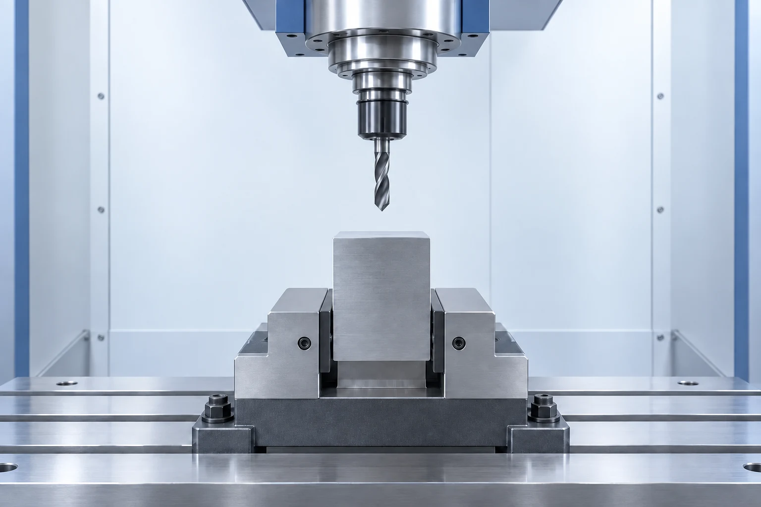
Workholding must resist the operation without distorting the feature being made. A thin plate supported only near its edges is different from a rigid block seated on a fixture. Moving a clamp can expose a hole while changing support. When assessing a quotation, ask which surfaces locate the part, where clamps act and whether the drawing’s functional faces remain protected.
Group holes by their approach direction
A vertical spindle can reach multiple top-face holes by repositioning in the table plane. It cannot turn a vertical drill into a horizontal one merely because the control has three linear axes. Side holes need the part or tool oriented appropriately, using the actual equipment and fixturing available.
Group the drawing’s holes by direction before comparing setup counts. Top-face holes, side ports and underside counterbores may form separate groups. An indexed rotary arrangement can bring another face toward the spindle, but the fixture must still hold the part and leave that face accessible. For straight holes, positioning at a fixed angle may be sufficient; continuously changing tool orientation is not automatically required.
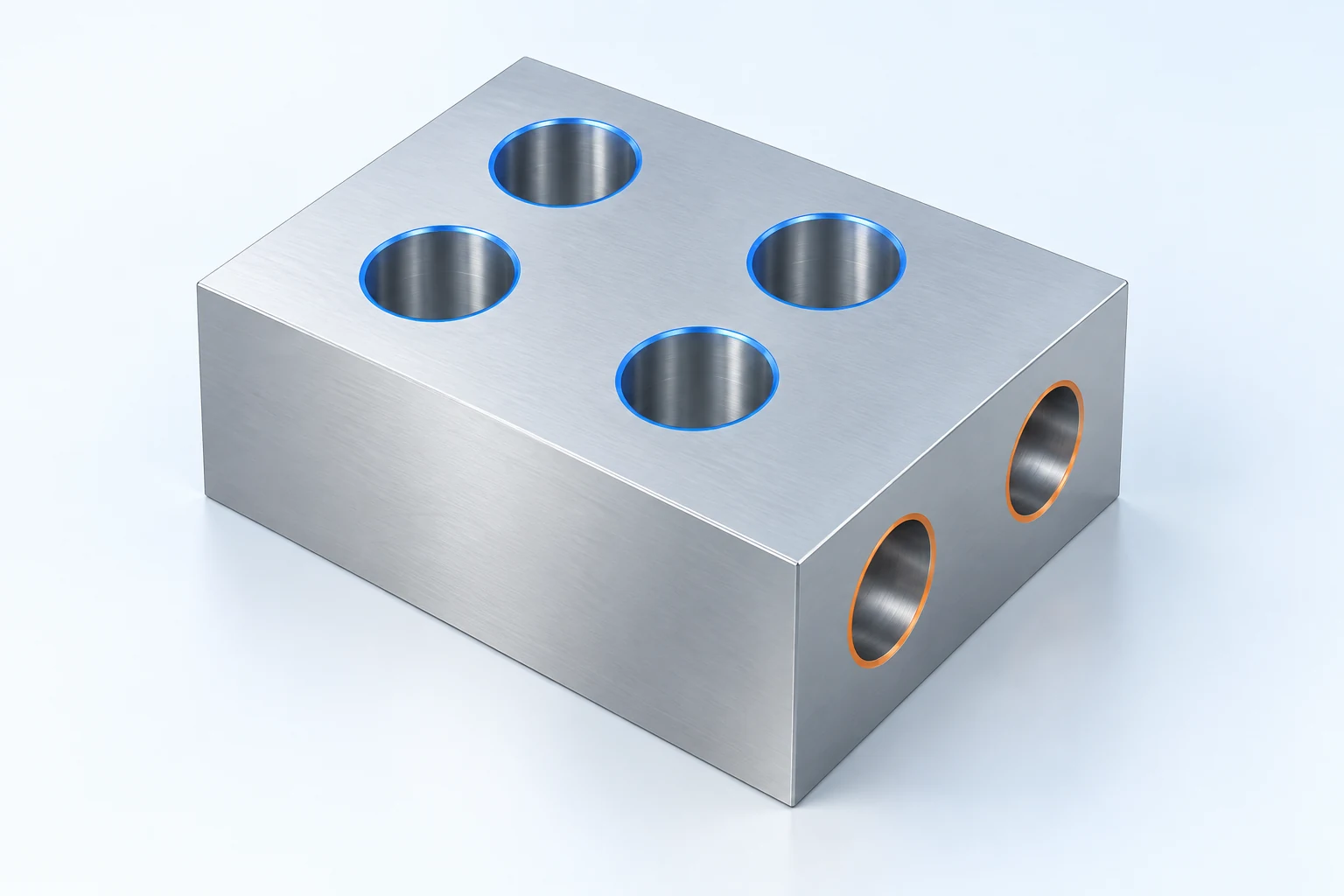
The important issue is the relationship between groups. If a side port must intersect a top passage, relocating the part must preserve their intended relationship. An attractive one-clamping proposal also needs scrutiny: a clamp covering an underside feature still prevents access. Compare the locating method and inspection approach rather than the advertised number of axes.
Our machining-process selection guide connects these access choices with the other surfaces on the part. A hole-making plan should fit that wider sequence, especially when a reference face is machined before the holes.
Hole depth depends on more than tool length
A drill needs usable cutting length and a path for chips to escape. Chip shape, tool geometry and coolant delivery affect that path. Through-tool coolant, where supported, differs from directing fluid toward the opening. [3]
Depth-to-diameter ratio helps describe the task, but does not approve it. A hypothetical 5 mm hole 50 mm deep has a depth-to-diameter ratio of 10. That arithmetic says nothing about the selected drill’s suitability, pilot requirements, material condition or coolant arrangement. Use it to communicate the geometry, then review the actual tooling system.
A peck-drilling cycle divides the advance into steps with programmed withdrawal behavior. Haas’s G83 documentation describes these motions and chip-clearing settings. The presence of that cycle does not make every long drill suitable for every deep hole; the chosen tool’s application instructions still govern the strategy. [4]
Entry and exit conditions deserve separate attention. An angled entry, a curved surface or an intersecting hole changes how the cutting edges engage. A prepared entry or a tool intended for that condition may be needed. These cases should be identified on the drawing review rather than treated as ordinary flat-entry drilling. [5]
Treat tapping as another operation with its own limits
For rigid tapping, axial feed and spindle rotation must remain synchronized with the thread pitch. A machine’s maximum spindle speed therefore should not be substituted for its specified tapping capability. Haas lists separate values for these functions, and its Mill Programming Workbook explains the speed/feed relationship for G84 tapping. [6]
On a blind threaded hole, distinguish required full-thread depth from the depth of the prepared hole. The tap’s leading geometry and bottom clearance occupy space beyond the usable thread. A pointed drill also leaves a conical bottom. The available material beneath the feature must accommodate the selected sequence without breaking through an unintended surface.

State the thread form, size, pitch, class and usable depth, plus any insert or final coating requirement. Let the proposed tool and process determine the necessary preparation; do not apply one universal extra-depth allowance to all threads. A bottoming tap reduces its lead length, but does not eliminate the need to evaluate the actual geometry.
Evaluate one complete hole pattern
Consider a hypothetical housing with eight clearance holes on its top face, two locating bores and one side port. The clearance holes may share a drill and approach. The locating bores need their own finish and verification plan. The side port introduces a second direction and an internal intersection. A single “maximum drilling diameter” cannot answer whether this housing is a good fit for a particular machine.
A useful supplier proposal connects those features in order: establish the reference surfaces, hold the housing, make and finish the accessible holes, reorient as needed, then complete internal edges and inspection. It should explain which requirements survive each relocation. This example describes a review method, not a prescribed production sequence.
Inspection must distinguish hole size from pattern location. Measuring one diameter does not establish where that hole lies relative to the part’s datums. Likewise, checking a thread with the agreed gauge does not prove that an intersecting passage is free of burrs. Choose evidence for the actual characteristic, including internal features that a simple external view cannot reveal.
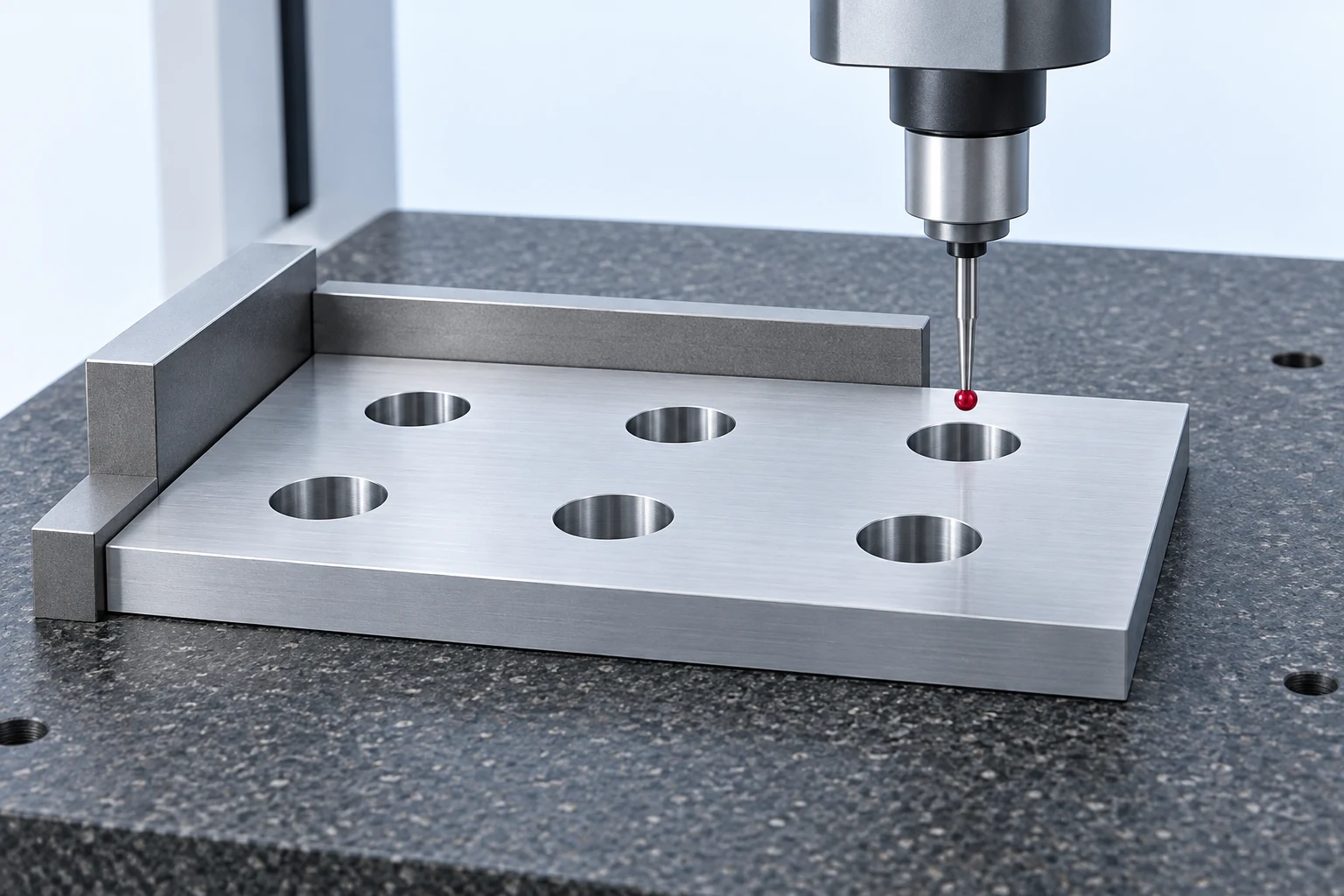
Finally, compare total work rather than drilling seconds alone. Setup, tool changes, reorientation, deburring and inspection can change the outcome of a machine comparison. Send the model, released drawing, material condition and quantities together; the CNC machining RFQ checklist helps keep that scope consistent between proposals.
Questions about CNC drilling capability
Does a CNC drilling machine need a pilot hole for every drill?
No. Pilot or entry preparation depends on the selected drill system and application. Deep-hole tooling may specify a compatible pilot; other drills are intended to start under different conditions. Follow the tool-specific method rather than adding a pilot automatically.
Can the same setup handle different hole diameters?
Often, if suitable tools are available and the tool changer, holders and clearances accommodate them. The harder question is whether all holes can be reached and accepted from that setup, particularly when their axes point in different directions.
Is an automatic cycle enough for unattended hole production?
No. The review also needs to address tool condition, chip accumulation, coolant supply and what happens when a tool fails. Programmed repetition alone does not establish that acceptable holes will continue to be produced throughout a batch.
Technical sources
- Haas Automation, DT-1: CNC Drill/Tap Center, machine functions and published configuration specifications, accessed September 29, 2026.
- Sandvik Coromant, What is reaming? and How to ream a hole, prepared-hole, stock-allowance and setup considerations.
- Sandvik Coromant, Drilling a hole, hole, component, machine and deep-hole tooling considerations.
- Haas Automation, G83 Normal Peck Drilling Canned Cycle (Group 09), withdrawal and chip-clearing behavior.
- Sandvik Coromant, Irregular surface drilling, angled entry, exit and intersecting-hole conditions.
- Haas Automation, Mill Programming Workbook, G84 tapping section; OSG, How is tapping depth calculated? (FAQ 9535; Japanese original), tapping synchronization and blind-hole clearance considerations.