On this page
Sinker EDM uses a shaped electrode to produce features such as blind cavities, recesses and narrow ribs. Wire EDM moves a continuously fed wire along a programmed path to cut through a conductive workpiece. For most part-selection decisions, the first question is whether the feature needs a floor or an open path through the stock—not which machine has the most impressive accuracy specification.
Both methods remove material with controlled electrical discharges. Their tooling, access requirements and finishing sequences differ enough that choosing the wrong one can add an unnecessary setup or make the intended geometry impossible. The comparison below follows a part from its drawing to its finished features.
The difference begins with the electrode
In electrical discharge machining, the electrode and workpiece remain separated by a small gap containing dielectric fluid. Discharges remove material locally, while the fluid helps carry debris away. Conventional EDM needs an electrically conductive workpiece; a hard material is not automatically an EDM candidate if it does not conduct electricity.[1]
The electrode determines how that removal reaches the required shape. A sinker electrode carries a three-dimensional form. A wire electrode is a slender line whose controlled movement creates a cut surface. That distinction explains why a blind mold cavity and a profiled die opening lead to different machining plans.
The term CNC EDM machine describes computer control, not a third EDM process. Wire and sinker machines can both use CNC. Comparing EDM with CNC milling is therefore a comparison of removal methods: electrical erosion versus a rotating cutting tool.
| Comparison | Sinker EDM | Wire EDM |
|---|---|---|
| Tool | Shaped electrode, commonly graphite or copper | Continuously fed wire |
| Typical feature | Blind cavity, recess or detailed internal form | Through opening, external profile or tapered through cut |
| Access | A collision-free approach for the electrode and holder | A continuous wire path between guides |
| Initial preparation | Electrode design, manufacture and alignment | Programmed contour, workholding and a threading entry |
| Roughing and finishing | Roughing and finishing strategies that account for electrode wear | Rough cut and, when required, skim passes |
| Common fluid arrangement | Oil-based dielectric | Deionized water; oil-based machines also exist |
The table describes common arrangements, not an interchangeable machine specification. Feature dimensions, material condition and the required surface determine the actual setup.[2]
What a wire can reach
A wire EDM machine guides a tensioned wire above and below the workpiece. Moving the workpiece relative to the wire generates the contour. The wire is an electrode, not a saw blade: it does not need teeth or mechanical cutting contact to remove metal.[3]
This arrangement suits punches, die openings, narrow through-slots and intricate external profiles. It also creates an access requirement. The wire must pass through the machining region and continue to its opposite guide. A pocket with a solid floor does not provide that route.
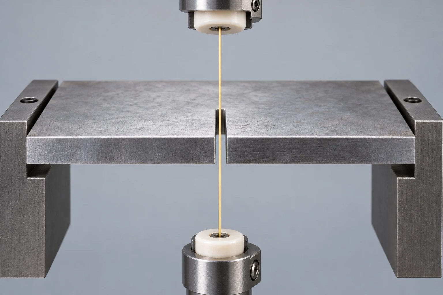
Upper and lower guide offsets allow suitable machines to cut tapers. The top and bottom contours can differ, but the wire still spans between them. That does not give it unrestricted access to a curved internal passage or an arbitrary sculpted surface.[2] On a drawing, identify whether a wall is straight, uniformly tapered or changes shape through its height; these are different programming problems.
For an external profile, the wire can enter from outside the blank. For an enclosed opening, a start hole within the material to be removed normally provides the threading location. That hole is a preparation feature, not necessarily a hole left in the finished part.
What a shaped electrode adds
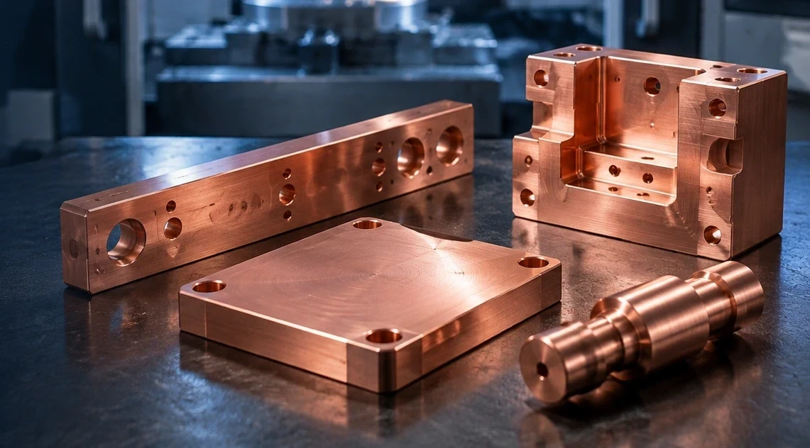
Sinker EDM is also called die-sinking or ram EDM. A shaped graphite or copper electrode approaches the workpiece and erodes the corresponding form while maintaining the discharge gap. It can create a cavity that stops within the block, retaining a solid bottom.[1]
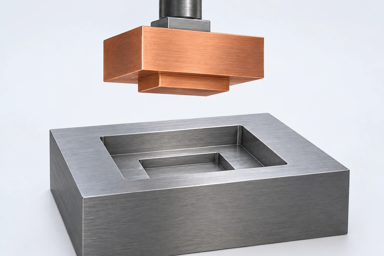
A useful distinction is between the cavity shape and the electrode’s access envelope. A cavity may be electrically machinable but still require several electrodes because one large form cannot reach every region without collision. The electrode holder, approach direction and space for flushing belong in the plan alongside the final cavity model.
Electrode preparation is part of the job. The tool needs the correct form, dimensional allowance and alignment to the workpiece datums. It also wears during use; roughing and finishing may require different electrodes or strategies. Ordering another identical cavity is different from ordering a new cavity shape because some preparation may be reusable, provided the existing tooling remains suitable.
Where an ordinary milling cutter can remove the bulk of a pocket efficiently, pre-machining can leave EDM to finish inaccessible detail, narrow features or difficult corners. The planned remaining stock matters: a cavity already milled beyond its final boundary cannot be recovered by an erosion process. The sequence should therefore be agreed before the first operation.
Start holes and slugs belong in the drawing discussion
Consider an enclosed opening in a plate. The start hole needs to reach through the stock, allow threading and connect to the intended contour by a lead-in path. Place it in the waste region. A hole outside the opening would require a connecting cut across material that may need to remain intact.

Cutting a closed contour usually frees a solid core, often called a slug. It does not turn all the enclosed material into chips. Before the contour closes, the machining plan must account for that core: retaining it temporarily, supporting and removing it, or using a suitable machine handling method. A loose core can obstruct the wire or lower hardware.[4]
This changes how a drawing is quoted. Several separate openings can mean several threading locations and several core-handling events, even if their combined perimeter is short. A detail that looks trivial in a top view may determine whether the operation can proceed unattended.
The finished surfaces also need to survive the last separation. If a retaining tab or cutoff location is used, its position and cleanup must suit the final drawing. It should not leave a witness mark on a functional sealing or locating face. State which surfaces matter rather than prescribing a tab arrangement without discussing the machining sequence.
A thin wire still needs a finite cutting width
The cut is wider than the physical wire because discharges occur across the side gaps. In an idealized straight cut, the geometric relationship is:
Kerf width = wire diameter + 2 × side gap.
For an assumed 0.25 mm wire and a 0.01 mm gap on each side, the kerf is 0.27 mm. The wire center is therefore 0.135 mm from either straight wall in this simplified cross-section. These inputs illustrate the geometry; actual compensation comes from the machining conditions, pass strategy and measured result.

That center-to-wall distance is not a guaranteed achievable internal corner radius. Cornering also involves wire behavior and the programmed path. Makino’s wire-lag discussion shows why straightness and profile error can vary through a workpiece’s thickness, rather than only at the top surface.[5] Specify a permissible corner radius instead of writing “sharp” and assuming a mathematically perfect intersection.
Sinker EDM also needs allowance for the discharge gap. Copying the finished cavity dimensions directly onto an electrode drawing would ignore the space in which erosion occurs. For a narrow cavity, electrode strength, wear and debris removal must be considered together. A fine-looking CAD detail is not, by itself, evidence that the same detail will remain accurate over the full burn depth.
Keep the acceptance requirement on the part drawing and let the electrode or wire program compensate for the process. The buyer needs a conforming feature, not a particular offset value divorced from the machine conditions.
Two drawings that lead to different process plans
A through opening in a hardened die plate
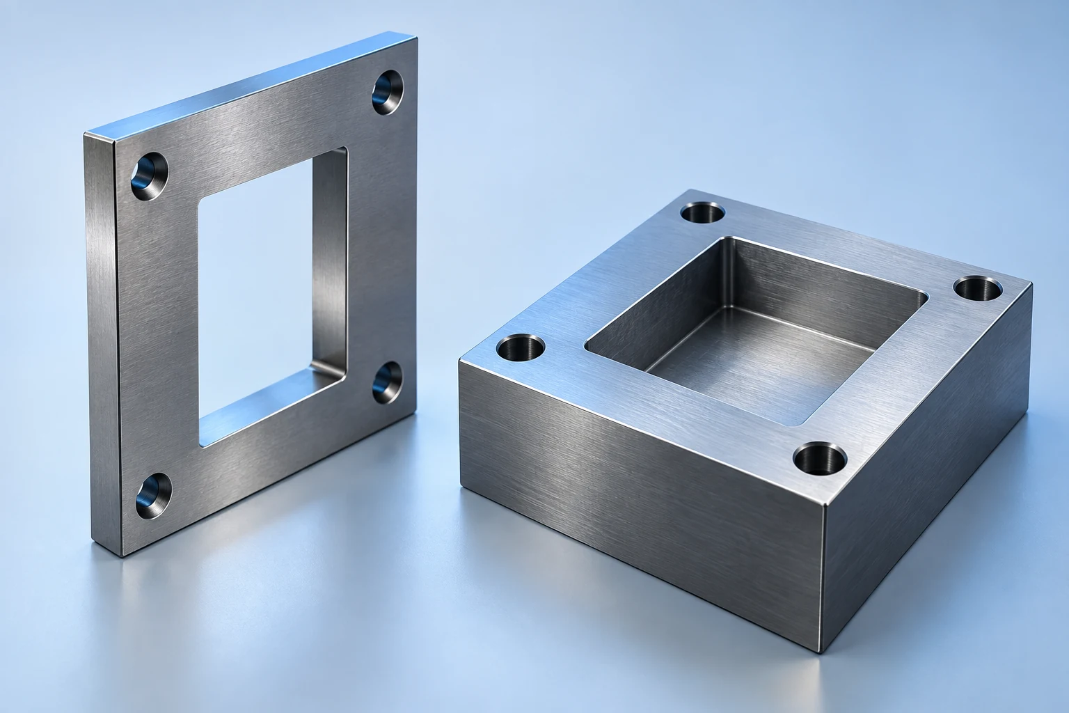
Take a 12 mm thick plate with an enclosed rectangular opening and a small locating notch. The opening passes through the full thickness, so wire EDM is a candidate. The useful starting information is the finished contour, its position relative to datums, the permitted internal radii and whether the walls are straight or tapered.
The preparation includes a start hole in the removable core. The cutting plan then covers lead-in, core retention or removal, finishing passes and final separation. Inspection should evaluate the notch and contour position as well as opening size. A single width measurement cannot establish that the entire profile is correctly located.
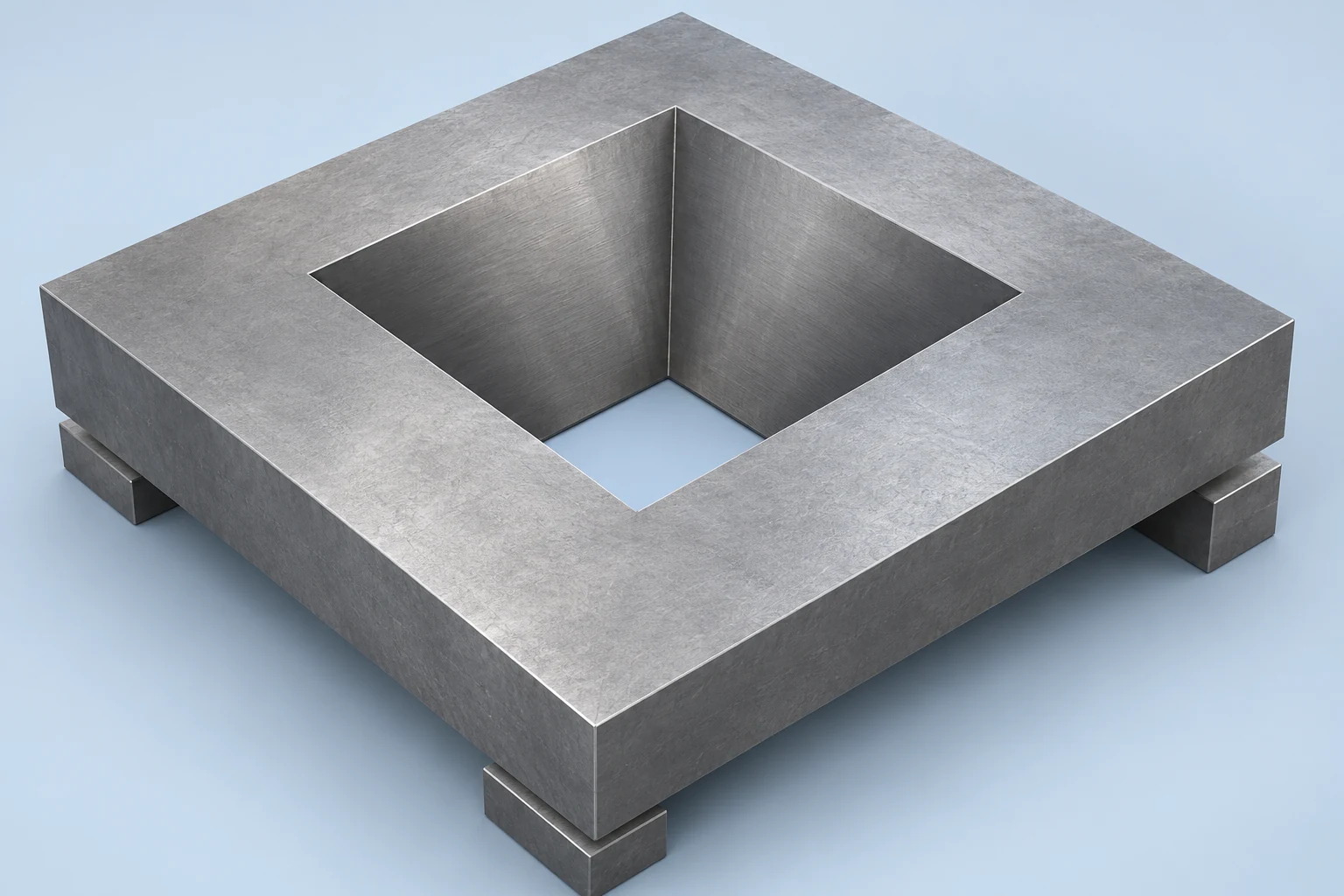
If the opening has different top and bottom dimensions, provide the relevant section or taper definition. Do not leave the programmer to infer a taper from a perspective view. The smaller opening, larger opening and intervening wall are all part of the required geometry.
A blind recess with a detailed bottom
Now take a thick mold insert with a recess 10 mm deep, a solid floor and a smaller step below the main pocket floor. Conventional through-wire cutting cannot create that complete blind form. Sinker EDM is a candidate if a shaped electrode can approach the feature and the workpiece conducts electricity.
A practical route might mill the accessible pocket volume, then use EDM for the remaining detail. The drawing must distinguish main-pocket depth, deeper-step depth, bottom radii and the datums used to locate the recess. Those requirements determine electrode geometry and setup; the outer block dimensions alone do not.
Neither example makes EDM the automatic choice for every feature on the part. Broad accessible faces, ordinary drilled holes and simple pockets may belong to other operations. The machining-process selection guide puts those operations into a complete part route.
Surface finish and surface integrity are separate requirements
EDM is a thermal removal process. Some molten material can re-solidify on the machined surface, forming a recast layer, while material beneath the surface can also be thermally affected.[6] The absence of an end mill pushing on the part does not mean there is no thermal effect.
Wire EDM may use a rough cut followed by skim passes to refine the surface and geometry. A machine maker’s published finish belongs to its stated conditions and pass sequence; it is not a universal result for every part.[7] A comparable quotation must include the finishing needed for the specified feature, rather than only the first cut.
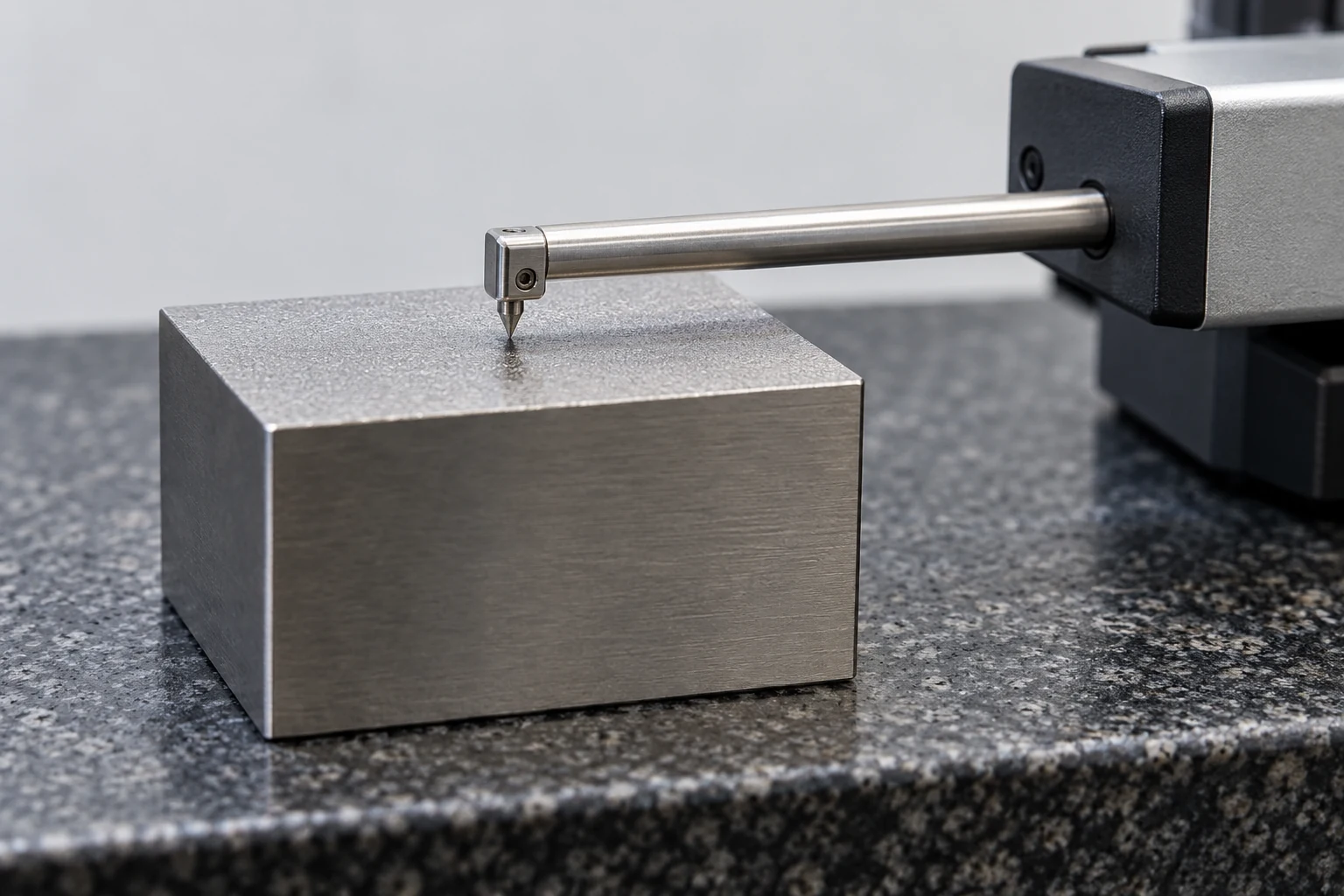
Separate roughness, dimensional accuracy and any surface-integrity requirement. A roughness reading describes surface texture; it does not establish recast-layer thickness or the absence of subsurface defects. If the design requires a limit on altered material, specify the governing requirement and an appropriate verification method. Do not assume a bright appearance proves compliance.
Secondary finishing can change dimensions, corner form and edges. Where polishing or material removal is required after EDM, define whether the drawing dimensions apply before or after that step. This is especially important for a fitted opening or a detailed cavity whose useful geometry could be rounded away during finishing.
Compare the complete work, not an hourly rate
Compare the work included in each process quote:
- Wire EDM: contour length, stock thickness, separate threading locations, finishing passes and core handling.
- Sinker EDM: electrode design and manufacture, the number of forms needed, burn depth, wear management and access for finishing.
Neither process has a universal price advantage.
Ask what is included in the quoted route. An electrode charge may cover reusable tooling; a low wire-cutting figure may exclude start-hole preparation or later finishing. Quantity matters because preparation is shared differently across repeat parts. A revised cavity shape can require new tooling even when the material and outside dimensions remain unchanged.
For a useful assessment through VETCNC’s EDM machining service, provide the drawing and model together. Identify conductive material grade and condition, the EDM features, accessible entry directions, datum references, tolerance and surface requirements, quantity and any required post-processing. The CNC machining RFQ checklist covers the wider drawing and delivery information.
The best process proposal explains how each difficult feature will be reached, finished and verified. “Wire EDM” or “sinker EDM” on a quotation is only the beginning of that explanation.
Frequently asked questions
Can wire EDM make a blind pocket?
Conventional through-wire EDM cannot make a complete pocket with a retained floor because the wire must continue through the workpiece. A part can combine wire-cut through features with a blind cavity made by milling or sinker EDM.
Should EDM happen before or after heat treatment?
EDM can machine hardened conductive material, so finishing selected features after heat treatment is an available route. The choice depends on distortion, remaining stock, datum preparation and the required final material condition. Agree the sequence rather than treating “EDM after hardening” as a rule for the entire part.
Does a contact-free process eliminate movement?
No. Cutting can release residual stress, and flushing, fixturing and thermal conditions still affect the operation. Low mechanical cutting force does not remove the need for support or an appropriate roughing and finishing sequence.[4]
Technical sources
- Sodick, Sinker EDM, process and material FAQ.
- Makino, Wire EDM Machine Centers Tutorial, guide motion and dielectric sections.
- Sodick, Precision Wire EDM Machine Tools, process FAQ.
- Camtek Software, Slugs, Stress and Taper.
- Makino, BellyWIZARD, wire lag and wall straightness.
- Makino, The Case for Additive Technology in EDM, discharge and recast explanation.
- Makino, U6 H.E.A.T. Extreme, rough-and-skim machining description.