On this page
Can a 1 mm wall be CNC machined? Sometimes. The useful question is whether that wall can be cut, held and measured at its actual height, span, material condition and tolerance. A short rib left against solid stock is a different job from a tall wall exposed on both sides. A turned sleeve adds the possibility of distortion under chuck pressure. A nominal thickness by itself cannot distinguish these cases.
Protolabs Network’s How to Design Parts for CNC Machining gives 0.8 mm for metals and 1.5 mm for plastics as recommended starting values, with thinner walls assessed case by case. Those figures describe that provider’s design guidance; they are neither a general machining standard nor a VETCNC capacity claim. Use a published number to flag a feature for review, then examine the part and the route that will make it. [1]
Define the wall before judging its thickness
First identify the two surfaces between which thickness is measured. On a milled enclosure, a rib may separate two pockets, while a thin floor is the material beneath one pocket. On a turned sleeve, wall thickness is the material between an outside diameter and a bore. These forms can share a nominal thickness but differ in loading, tool approach and inspection. An opening through a wall also creates a narrow ligament beside the hole; its local minimum may be smaller than the wall callout elsewhere.
Record the minimum local thickness, not only the CAD value at one easy-to-measure point. A tapered wall, filleted root, cross-hole or intersecting pocket can put the thinnest section away from the obvious section view. Wall height means unsupported distance from a stiff root to a free edge; span means distance between supports along the wall. A 2 mm wall standing 5 mm high and one standing 40 mm high should not receive the same risk judgment merely because their thickness callouts match. Del Sol and colleagues describe height relative to thickness, changing stiffness and support conditions as central to thin-wall behavior during milling. [2]
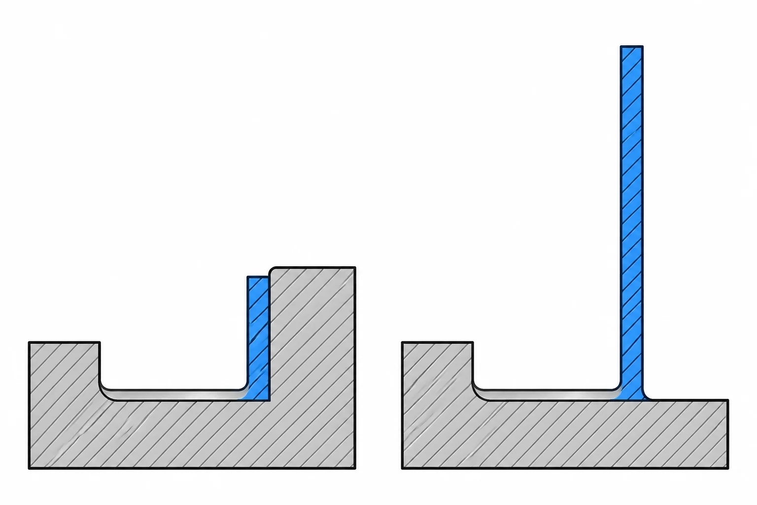
Thickness also has to be read in the final part state. A thick blank may support a future rib during roughing; removing the opposite pocket later leaves the final thin wall. The design review therefore needs a simple account of which material exists at each cut, which surface can be clamped, and when the feature first becomes flexible. The CNC milling design guide covers the broader pocket, corner and tool-access decisions; the focus here is the wall through that changing sequence.
Three wall forms create different machining problems
The feature form matters more than a single metal-versus-plastic minimum. Use this table to identify the likely source of movement and the condition that must be checked at the end. Each support option still has to clear the tool and preserve the part’s functional surfaces.
| Feature | Main movement risk | Useful support or sequence | Finished-state check |
|---|---|---|---|
| Milled rib between pockets | Bending as the second pocket removes backing stock | Alternate sides or finish in stages while material remains below the cut | Thickness and straightness after release |
| Pocket floor | Deflection toward an unsupported void under tool or clamp load | Support beneath the floor where the fixture and access permit it | Remaining thickness and floor form in the released part |
| Turned sleeve | Ovalization under grip or radial cutting force | Grip a stronger land or distribute contact around the sleeve | Bore, outside diameter and roundness after unclamping |
A support that helps one feature can block another. Backing a floor directly under the cutter is useful only if the support can touch a suitable surface and the workholding still locates the part correctly. A sleeve gripped on its finished thin wall can be held securely yet spring away from its as-clamped shape afterward. The table is a route to the next question, not a substitute for a fixture or an acceptance drawing.
Cutting, clamping and stress release move a wall differently
Cutting-force deflection happens while the cutter is engaged. The wall or the tool moves under load, so a programmed path may remove less or more material than expected at a particular height. When the force leaves, elastic recovery can leave taper or variation along the wall. Chatter is a dynamic problem: the flexible wall and tool can vibrate, often leaving a patterned finish. A smoother-looking surface alone does not prove the size or form is correct. Research on light-alloy thin-wall machining separates static displacement from vibration and notes that part stiffness changes as material is removed. [2]
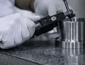
Clamping distortion begins before the cut. Jaws or a clamp can force a compliant feature toward the intended cutter path. A measurement taken while the part is still held may look good, yet the shape changes after release. Carr Lane’s fixture guidance places clamp loads toward locators and strong support regions rather than across an unsupported flexible section. A support is useful when it resists the cutting load without pre-bending the surface it is meant to protect. [3]
Post-machining movement can remain after the tool and fixture loads are gone. Removing material changes the balance of residual stress already in a blank and stress introduced during machining. In an experiment on rolled EN AW-2024 T351 samples, Zawada-Michałowska and coauthors measured different deformation after milling under different strategies and feed directions relative to rolling. Their measured values belong to that material and experiment, but the result demonstrates why the final free-state shape cannot be inferred from wall thickness alone. [4]
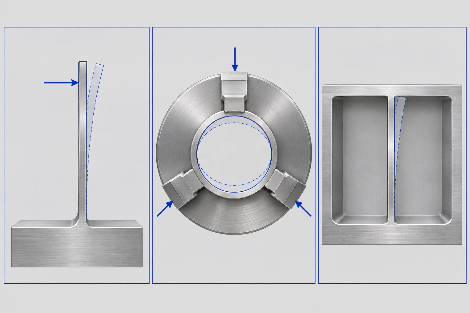
These mechanisms call for different responses. A wall that bends only under the cutter may need reduced local force or temporary support. A wall distorted by clamping needs a different contact scheme before cutting data is adjusted. A part that moves after release may need a changed stock-removal sequence and a final inspection plan. Treating all three as “the wall is too thin” hides the cause and can prompt an ineffective design change.
Mill a rib while it still has backing stock
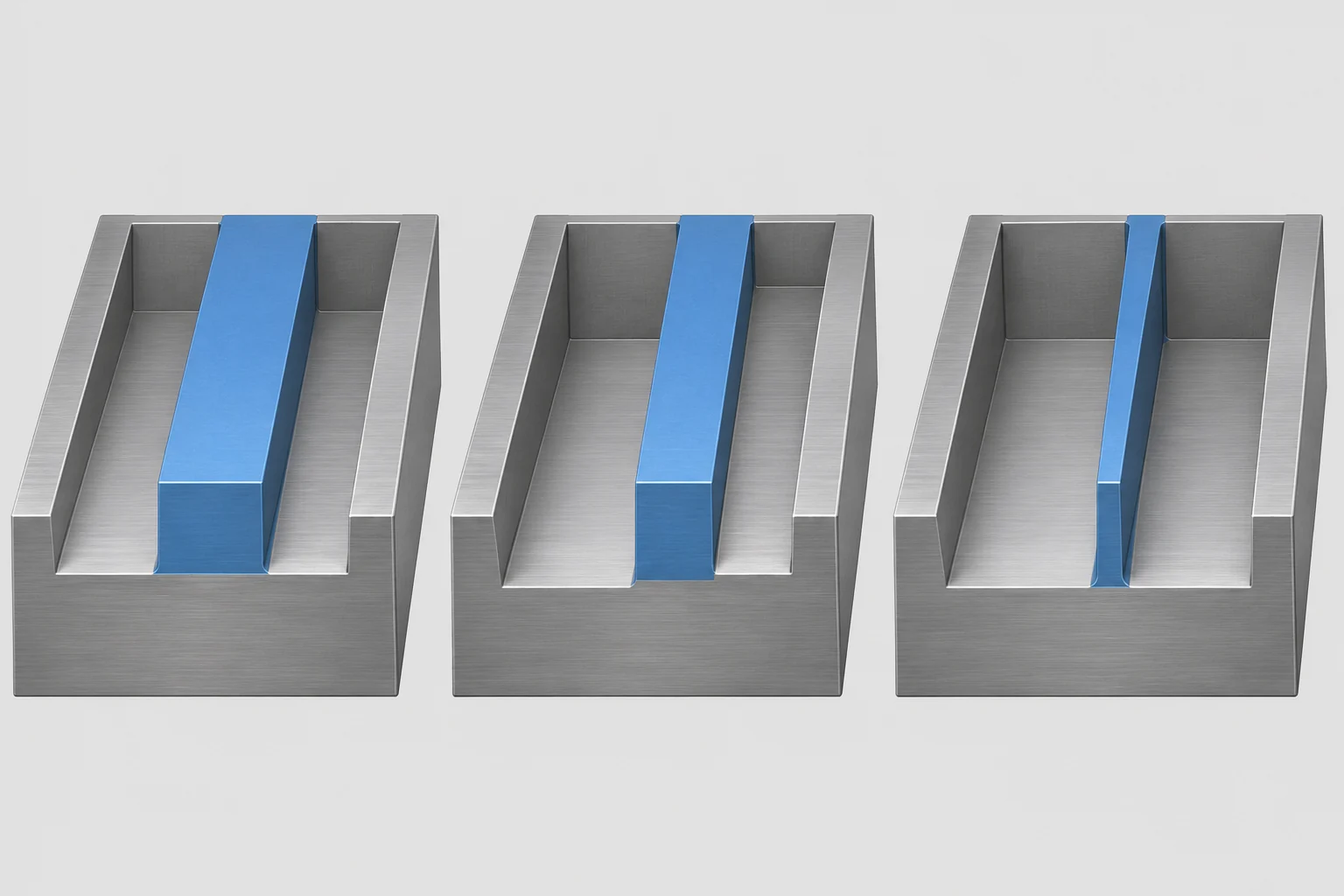
For a rib between two pockets, the wall has two lives. During the first pocket, material on the far side still backs it. During the second pocket, that material disappears and the remaining section becomes easier to deflect. A process planner can retain stock near the future wall, remove material from both sides in stages, and reserve final passes for a state closer to the finished geometry. Harvey Performance Company’s Your Guide to Thin Wall Milling describes stepped axial cuts and progressively controlled radial engagement while the remaining stock supports the wall. The number and size of cuts depend on the specific material, tool and wall. [5]

The tool assembly has its own stiffness limit. A deep pocket may require a long reach to finish the wall; using a longer cutting length than the contact requires can make tool deflection harder to control. A shorter cutting edge on a relieved neck can sometimes reach the wall while keeping more material in the tool body, but the full holder still needs collision clearance. This is a tool-access decision, not permission to assign a universal maximum wall height. [5]
Do not write “light finish pass” on the drawing as though it guarantees a thin rib. A finish pass removes less stock, but if the wall has already lost backing, even that load may move it. The order of roughing, any intermediate hold, the remaining allowance and the point of final measurement belong in the actual manufacturing plan. The drawing should state the required final geometry; the shop decides the toolpath that can achieve it.
Pocket floors and openings change the support path
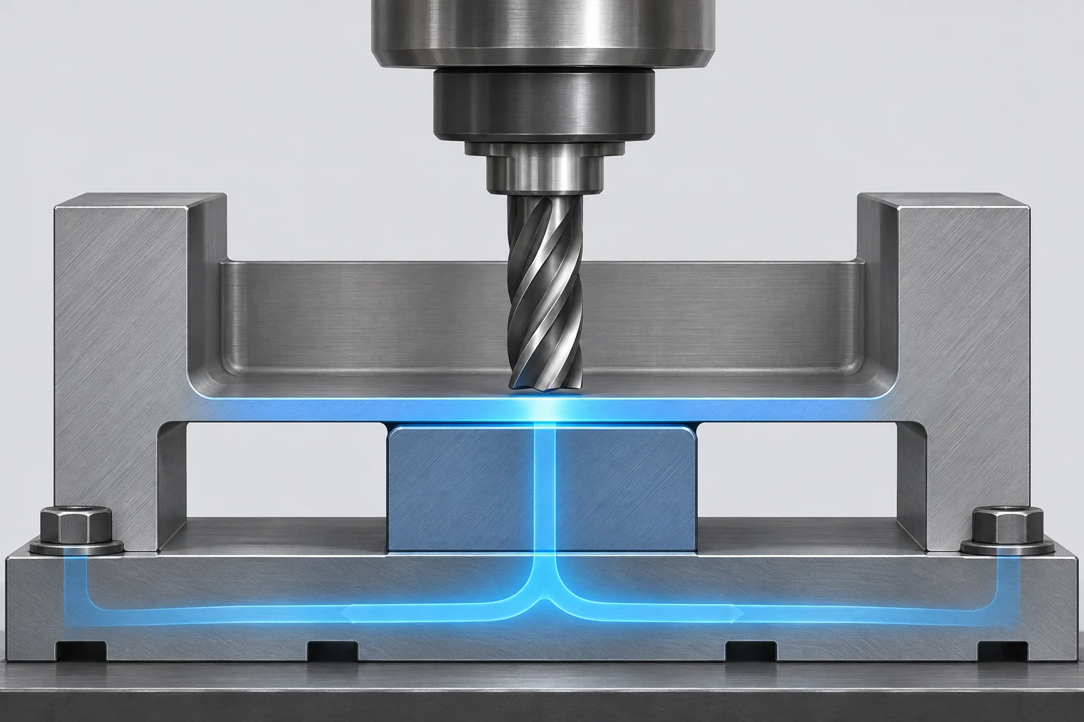
A thin pocket floor is loaded through its area rather than along a free top edge. A cutter, clamp or inspection probe can bend it toward the open space underneath. A fixture may support the underside, but only if that surface is accessible and the support does not force the floor into a shape it would not have after release. When a floor is also a sealing or locating face, the finished condition of that face matters more than a convenient as-clamped reading.
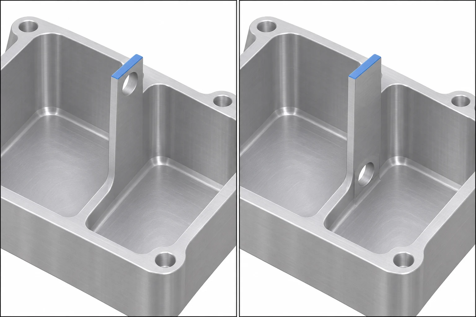
Openings can turn a seemingly continuous wall into separate flexible tabs. A port near the free edge removes a strip of material that would otherwise carry load back to the root. Two neighboring pockets can leave a long unsupported panel even when the nominal wall thickness is generous. Before increasing every wall, identify the feature that is actually moving. Shortening a nonfunctional free edge, changing an opening’s position, or adding a local rib may improve support without changing a critical mating face. If the part is primarily a constant-thickness panel with bends and cutouts, the machining versus sheet-metal comparison helps evaluate a different route; it is not a fix for a housing whose deep pockets and precision interfaces require machining.
A thin turned sleeve can spring back after chucking
A cylindrical sleeve is not a milled rib wrapped into a circle. It rotates while the outside or inside surface is cut, and the grip can act directly on the wall. A three-jaw chuck applies load at separated contact regions; on a compliant sleeve, that can change the bore or roundness while the jaws are tight. A published 7075 aluminum deep-hole boring experiment used an auxiliary support jacket because direct three-jaw gripping risked deforming its particular tube. The experiment’s 5 mm wall is a description of its test piece, not a threshold for other tubes. [6]
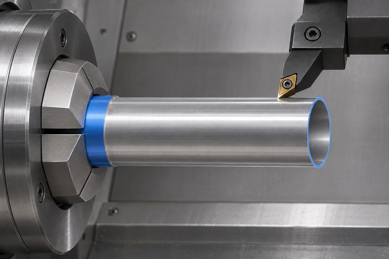
Where the design allows it, a stronger grip land, a suitable collet or supported contact can move clamping load away from the finished thin section. The tool choice also changes the force that reaches the wall. Sandvik Coromant’s turning handbook discusses entering angle, depth relative to insert nose radius and sharp-edge geometry for slender or thin-walled components; these are setup-dependent ways to reduce problematic radial force, not a blanket recipe for every metal. [7]
A sleeve may have an acceptable outside diameter while its bore is out of round, or an acceptable bore size at one angle while minimum wall thickness is elsewhere because the bore and outside surface do not share the intended axis. Define which interface locates the sleeve in the assembly. The CNC turning design guide develops the broader choices around grips, grooves and bores; here the thin wall makes the grip and released-state inspection decisive.
Change geometry where function permits it
Not every wall needs to be thickened uniformly. Start by marking the surfaces that actually fit, seal, guide or clear another component. Material outside those interfaces may be available for a broader root, a local rib or a shorter unsupported span. A rib that improves stiffness but blocks an end mill or the mating component is not an improvement. A thickened floor that removes a required cavity depth is also a functional change, not a free DFM gain.
For a wall whose slenderness is unavoidable, the route shifts toward temporary support, staged stock removal and verification after the wall is free. The change can increase setup, fixture or inspection work even if the final CAD shape stays the same. Conversely, accepting a slightly thicker noncontact region may remove the need for special support. Such tradeoffs should be compared against the complete finished part, not against a single wall number or machine-hour rate.
The fixture design guide explains how locators, clamps and supports establish repeatable position. For a specific thin wall, the additional question is whether the support remains useful as stock disappears and whether it contacts a surface that may be loaded without changing the part’s acceptance geometry.
Review a thin wall in a workable order
A design review can be brief if it follows the actual dependency between function, geometry, process and acceptance:
- Mark the functional surfaces. Identify what the wall touches, clears, seals or supports. Note whether thickness, straightness, flatness, roundness or location controls that function. A cosmetic wall and a sealing wall need different evidence.
- Measure the local feature. Record its minimum thickness, unsupported height and span, root shape, nearby holes or slots, and the material grade and condition. For a sleeve, include bore size, outside diameter and the intended grip region.
- Trace when support disappears. Show which stock backs the wall during each pocket, bore or turning operation. A wall stable in the first setup may become flexible after the opposite side is removed.
- Test the likely load path. Identify where the cutter force enters and where clamps or supports carry it. If a fixture loads the functional wall, compare another contact scheme before assuming a slower cut alone will solve the problem.
- Define the accepted state. State the required finished dimension and geometric relationship, and whether the part is checked released or under specified restraint. Choose a measurement method that can reach the relevant surface without bending it enough to hide the result.

Thickness at one point is not the entire acceptance question. A milled rib can be within size yet bow away from the required mating plane. A turned sleeve can meet two separate diameter sizes yet have a poor relationship between their axes. Where that relationship matters, put it on the drawing using appropriate datums and geometric controls. Do not assume a generic drawing note or a machine’s positioning specification establishes the finished wall’s form. If inspection requires a restraint, specify the restraint and its relation to the assembly rather than silently measuring a deformed part in its machining fixture.
Worked review: two states of the same 2 mm wall
Consider a hypothetical aluminum housing with two adjacent pockets and a nominal 2 mm rib between them. The rib has a functional face that locates an internal insert. During the first pocket, solid stock still lies on the other side. In a drawing review limited to the final 2 mm number, that temporary support is invisible. During the second pocket, the rib’s opposite side is exposed; its free height and length then determine how much of it can bend under the finishing cut. The shop also needs a location that can be clamped without pushing on the new thin face.
Suppose the wall is 30 mm high over most of its length but only 8 mm high near one end because a cross member meets it there. Those regions have the same nominal thickness and material, yet the taller span is the more plausible place to check for movement. One design option is to reduce the unsupported height where the insert does not need full clearance. Another is a local support rib outside the insert’s envelope. If neither geometry change is possible, the machining sequence must retain support as long as practical and the finished wall must be inspected after release. The illustration of these states does not establish that 2 mm is safe or unsafe; the material, exact span, required form tolerance and real setup remain necessary inputs. [2] [5]
Now compare the acceptance question. A thickness measurement at the rib’s base could pass even if the free edge bends away from the insert. The functional face’s position relative to the housing datum may therefore matter in addition to thickness. This leads to a better request than “Can you machine 2 mm?”: provide the model and drawing, identify the functional face, mark the 30 mm exposed span and ask which support and inspection route can meet the specified finished condition. If a process proposal requires a rib or wall revision, evaluate the insert clearance before accepting it.
Questions about CNC wall thickness
Can a 0.5 mm aluminum wall be CNC machined?
It can be feasible for some geometries and processes, but 0.5 mm is not a blanket production or tolerance promise. Protolabs Network lists 0.5 mm metal walls as a case-dependent feasible value under its own guidance. Height, span, material condition, support, function and measurement requirement decide whether a particular design is viable. [1]
Do plastic parts always need a thicker minimum wall than metal parts?
No single comparison covers every plastic, metal or wall form. Protolabs Network’s general design guide recommends 1.5 mm for plastics versus 0.8 mm for metals, citing lower stiffness, residual-stress warping and temperature sensitivity as concerns. Those are screening values for its guidance, not acceptance limits for an unspecified part. [1]
Why can a wall measure correctly in the fixture but fail after unclamping?
The clamp may hold a flexible wall in a displaced position, or the part may move as residual stress rebalances after stock removal. Once the load is removed, its free-state shape differs. Measure the state required by the drawing or assembly, and define any allowed inspection restraint explicitly. [4]
Can I apply a milled-wall thickness guideline to a turned tube?
Only as a preliminary flag. A turned tube also experiences chuck contact and radial cutting loads around a cylindrical wall. Its grip, bore, outside diameter, roundness and released-state relationship need their own process and inspection plan. A minimum for a short milled rib does not answer those questions. [6] [7]
Technical sources
- Protolabs Network. How to Design Parts for CNC Machining, “Thin walls.” Provider-specific recommended and case-dependent feasible wall values; internal research record retains the source URL.
- Del Sol, I., Rivero, A., López de Lacalle, L. N., and Gamez, A. J. Thin-Wall Machining of Light Alloys: A Review of Models and Industrial Approaches. Materials 12 (2019), 2012. Wall geometry, changing stiffness, deflection and support during milling.
- Carr Lane Manufacturing. Locating & Clamping Principles for Jig & Fixture Design. Directing clamp load into locators and supported, strong workpiece regions; internal research record retains the source URL.
- Zawada-Michałowska, M., Kuczmaszewski, J., Legutko, S., and Pieśko, P. Techniques for Thin-Walled Element Milling with Respect to Minimising Post-Machining Deformations. Materials 13 (2020), 4723. Controlled EN AW-2024 T351 experiments on stock history, process strategy and released shape.
- Harvey Performance Company. Your Guide to Thin Wall Milling, 2017. Stock-supported, staged axial and radial milling guidance; internal research record retains the source URL.
- Yang, S., Tong, J., Liu, Z., et al. Experimental Study on the Roundness of Deep Holes in 7075 Aluminum Alloy Parts by Two-Dimensional Ultrasonic Elliptical Vibration Boring. Micromachines 14 (2023), 2185. Auxiliary support jacket used with the study’s long 7075 aluminum tube to limit chuck-induced deformation.
- Sandvik Coromant. Turning Handbook, “Slender/thin wall components,” p. 12. Entering angle, insert geometry and cutting-force direction; internal research record retains the handbook URL.