On this page
Design a CNC-turned part around the surfaces that make it work: the bore or outside diameter that locates it, the shoulder that seats it, and the end face that sets its installed length. Then leave a way to grip the blank, reach each surface, separate the part from stock, and verify it after release. A profile can be rotationally symmetric and still be difficult to finish if its only useful grip surface is already a delicate fit, a shoulder hides a corner, or the far end becomes a critical face after cutoff.
This guide addresses those drawing decisions for shafts and hollow turned components. The turning operations guide explains how OD turning, facing, grooving and parting create features. Here the objective is to decide what geometry may change without changing the assembly and what the finished drawing must actually control.
Start with the axis and faces that locate the assembly
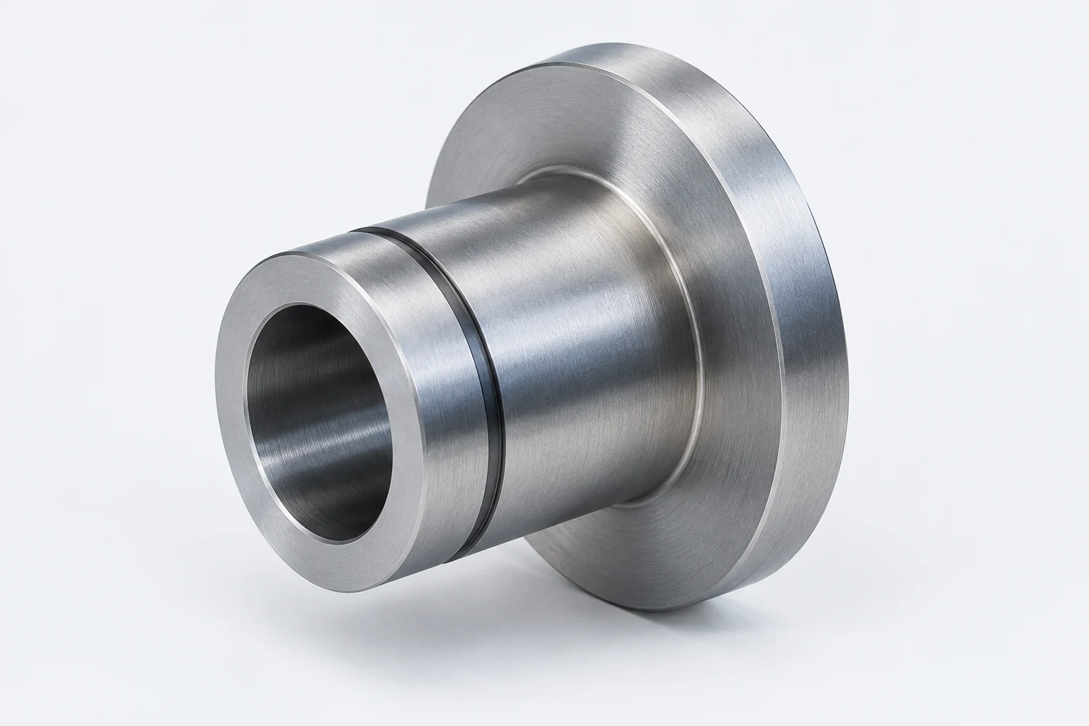
For a flanged bushing, the bore may locate a pin, the pilot OD may enter a housing, and the flange face may stop axial travel. Those are three distinct functions. The bore’s size governs its fit to the pin; its relationship to the pilot governs how the pin sits in the housing; the flange face controls where the assembly stops. Holding all three to an arbitrary, very tight general tolerance would obscure which relationship matters. Leaving only nominal dimensions is equally unhelpful.
Identify the actual assembly contacts on the model before asking for a shoulder relief, a different groove or a shorter body. If the flange bears on an annular seat, mark the contact land that must remain. If the far end only clears another part, it may have a different length requirement from a face that positions a bearing. A nominally decorative chamfer can still be functional when it leads a press fit or protects a seal. Review the mating component, not the turned component in isolation.
A drawing can use a functional cylindrical feature to establish a datum axis and a seating face to establish an axial reference. The selection and order depend on how the assembly locates the part. ASME Y14.5-2018 (R2024) provides the drawing language for dimensions, datums and geometric relationships; its public description does not assign a ready-made tolerance to this bushing. [1] A stock end or a chuck surface is a convenient manufacturing reference only if it also represents the intended design relation.

Reserve a workable grip before finishing the profile
A lathe must transmit torque to the workpiece while the tool applies load. On a bar-fed route, extra stock behind the future part can provide a grip while the exposed OD, bore and front face are machined. On a cut blank, jaws may instead hold an existing diameter or a dedicated fixture surface. The drawing should establish the final part boundary; process planning can decide whether temporary stock is added. But the designer needs to notice when every accessible surface is a finished seal, bearing or cosmetic face that cannot tolerate ordinary jaw contact.
Consider the second grip as well as the first. A part turned at one end and then reversed may be held on a finished OD or inside a finished bore. Haas describes machinable soft jaws that can be bored for a particular diameter, and its lathe setup material distinguishes those from hard jaws that may mark a finished surface or introduce runout in a second operation. [2] [3] That is a workholding option, not a guarantee that any thin sleeve can be clamped without distortion. The actual jaw contact area, part section and allowed surface condition need review together.
A long exposed small-diameter section raises a different problem: the cutting load can bend the workpiece, and support must be available near the span that needs it. A center can support an end if that end can accept a center feature or sacrificial stock; a steady rest needs a suitable contact surface. Excess tailstock pressure can itself deform stock, as Haas notes in its troubleshooting guidance. [4] The slender-shaft deflection guide treats the force and measurement problem in detail. For design release, show which final surfaces cannot carry center marks or support contact and which end may be finished afterward.
Keep the seating land when opening a shoulder corner
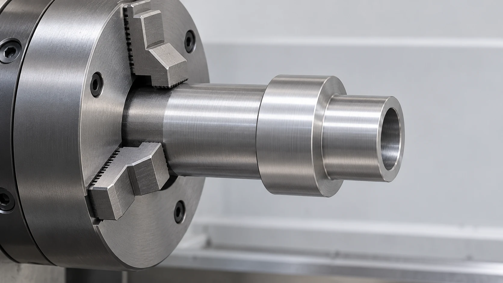
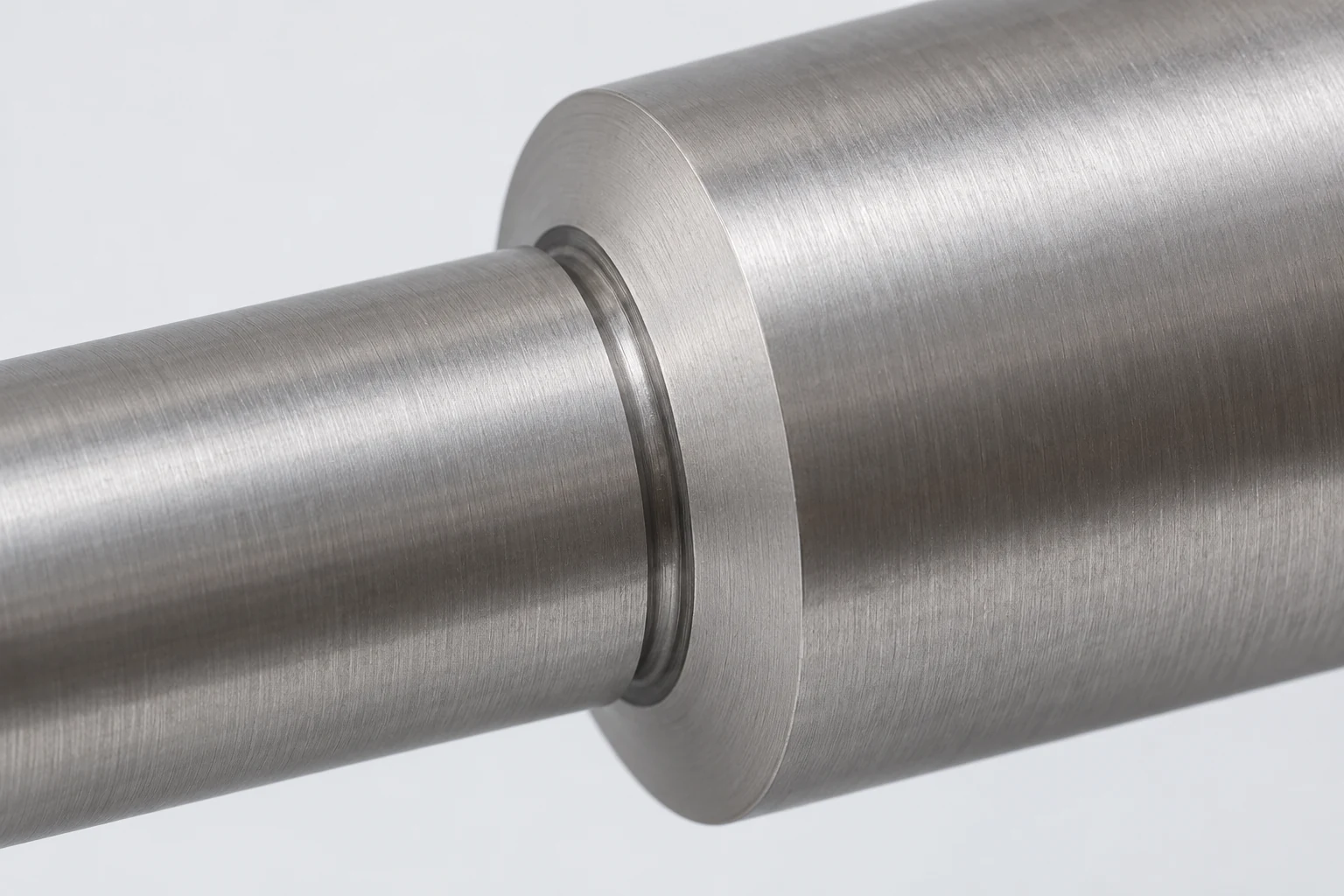
A turned step brings an OD and a face together. The tool’s cutting edge and holder need clearance at that intersection. Sandvik Coromant’s external-turning guidance treats a square shoulder, profile change and corner relief as different accessibility conditions for the tool assembly. [5] The design question is how much of the corner can change while the mating part still sits where intended.
If a ring, bearing or washer must seat against the shoulder, inspect its inside edge or chamfer. A compatible fillet on the shaft may be acceptable when the mating corner clears it. A narrow local relief can also let the tool finish the OD and face without leaving an unwanted blend at the seat. Neither option is automatically better: a large fillet may hold the mating face off its seat, while an overwide relief may remove the annular land that carries load. Define the face area that must contact, the permitted corner shape and the required OD transition together.
For a shaft with several adjacent steps, leave enough axial room for the tool body to approach and withdraw at each shoulder. A drawing can show a narrow recess that a cutting edge appears to fit, while the holder would strike the next step. A different insert or holder may solve the route, but the turning tool guide belongs to that process choice. The released design should state the finished contour and the protected seat, not prescribe a particular insert code without reason.
Check the groove’s mating fit and the metal behind it
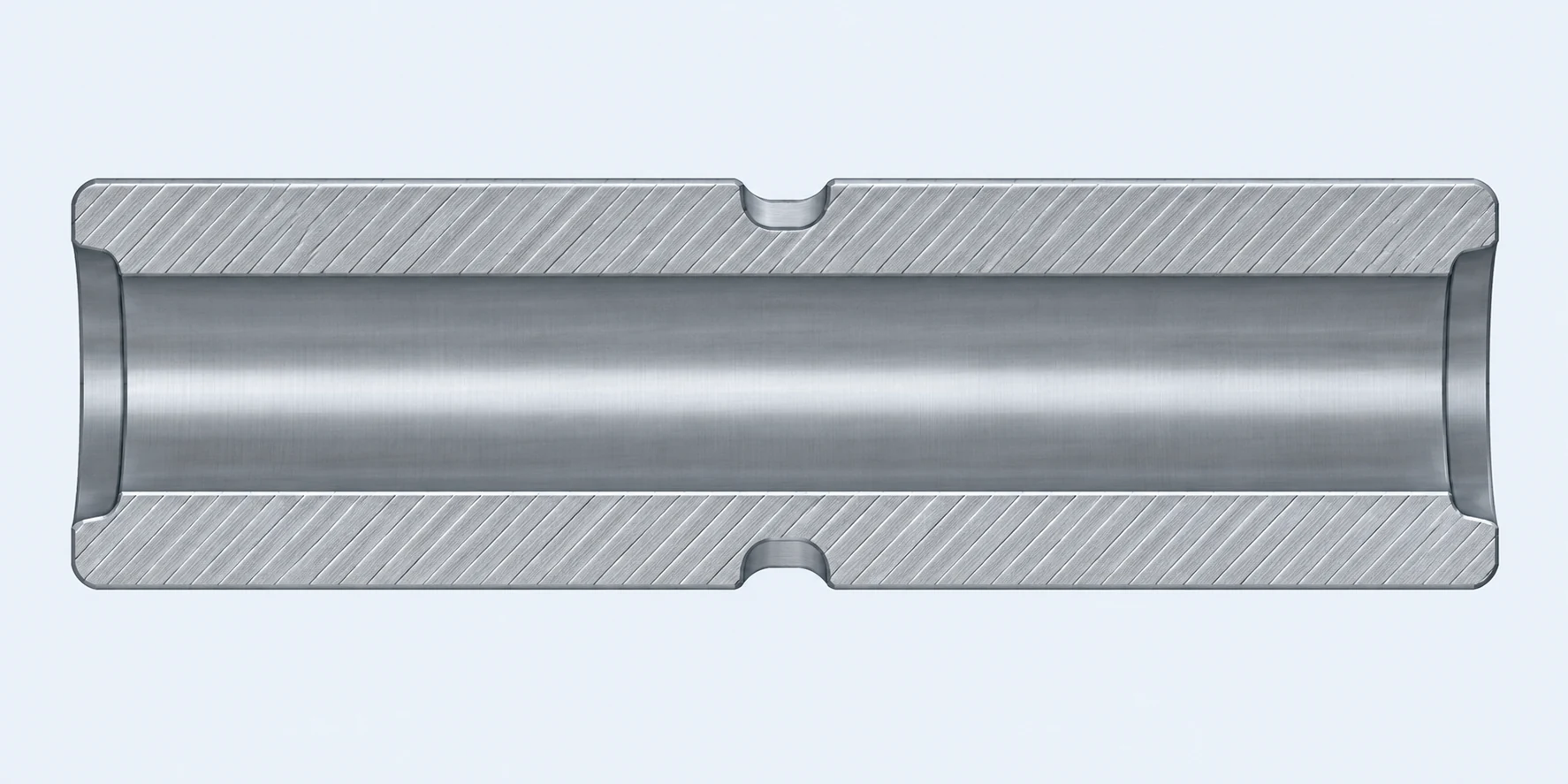
An external groove is an annular feature, but its purpose changes the design. A retaining ring needs a groove compatible with the selected ring and its load case; a seal needs its gland geometry and surface requirements; a clearance undercut may only need to clear a mating corner. Do not apply one nominal groove width or root radius to all three. Put the selected component requirement on the drawing or in a controlled specification, then call out the groove width, root diameter, axial location and edge condition that implement it.
A groove around a hollow sleeve also removes wall material at its root. Suppose a proposed drawing gives a 17.0 ± 0.1 mm groove-root diameter around a 12.0 ± 0.1 mm through-bore. For ideal concentric cylinders, nominal radial metal is (17.0 − 12.0) ÷ 2 = 2.5 mm. Using the smallest permitted root diameter and largest permitted bore gives (16.9 − 12.1) ÷ 2 = 2.4 mm. Those diameter limits alone do not control local minimum wall if the axes are offset. If the actual bore axis is 0.10 mm from the groove axis in an otherwise ideal section, the thinnest local wall becomes 2.4 − 0.10 = 2.3 mm. The 0.10 mm offset here is a stated calculation input, not an implied tolerance.
This calculation answers a geometry question, not a strength or fatigue question. The designer must separately assess load, material, groove root form and the chosen mating element. It also shows why a groove diameter and bore diameter can both pass size inspection while the minimum wall is still uncertain: their relative position matters. Sandvik Coromant notes that deep grooves create tool overhang, coolant and chip-removal challenges and that a wide groove need not be cut in one insert-width plunge. [6] Specify the finished groove for function, then review the route against that geometry.
Design the bore for the complete boring assembly
A modeled hole may be open at the mouth yet hard to finish at its deepest functional diameter. An internal turning tool has a cutting edge, head and bar body; all must enter and clear the bore at the required depth. Sandvik Coromant identifies hole diameter, length and tool overhang as linked constraints and favors the largest practical tool section with the shortest practical overhang for stability. [7] A small tip that fits through the entrance does not prove that its supporting bar can finish a long, narrow internal seat.
Separate the useful bearing or seal length from extra cavity depth. If the assembly only requires a short finished bore followed by clearance, the drawing can define that functional length and allow a larger or differently shaped noncontact region beyond it. If the bore terminates at a functional internal shoulder, retain the shoulder but give its corner and chip exit enough room for the selected route. Do not remove a stop or sealing land merely because it complicates boring. Likewise, do not substitute a drilled-size callout for a required finished bore: hole creation and final internal turning may be distinct steps.
For a thin sleeve, bore size can also change after the jaws release or after the part is parted. State the condition in which a fit must be accepted. An in-chuck reading may be useful during setup, but it is not automatically the installed part’s size. The actual material, wall section, chucking and finishing sequence determine whether a process review is needed; no universal minimum bore or wall number follows from this article.

Expose radial features and the second end
Ordinary turning makes surfaces symmetric about the spindle axis. A radial port, off-center hole, wrench flat or side slot breaks that symmetry. Depending on the machine, such a feature may be cut with indexed live tooling or in a separate milling setup. Haas Tooling describes axial and radial driven holders for secondary drilling, milling, flatting and tapping on equipped lathes. [8] That does not imply every CNC lathe or VETCNC setup has those options. The live tooling and mill-turn guide explains the route choices.
Show the radial feature’s angular position when it must align with another feature, and locate it axially from a functional face. A radial port into a bore also creates an intersecting internal edge; if flow, cleaning or assembly makes that edge important, define its accepted condition. If angular orientation does not matter, do not impose an unnecessary clocking requirement merely because the CAD view happens to show the port at the top.
The far end needs its own decision. Parting separates the component from bar stock, but a cutoff face can carry a pip, burr or other condition that may be unsuitable as a seating or length datum. Sandvik Coromant discusses the tradeoffs of parting-tool geometry and the possibility of pip and burr formation. [9] If the second end locates a bearing or controls overall length, define its final face and allow a way to rehold and finish it. If it only clears a neighboring component, specify the needed clearance and edge condition without treating it as a precision seat.

Match each revision to the interface it changes
These changes can make the part easier to produce only when the adjacent function remains satisfied. The table keeps the design change and its consequence together; it is not a set of standard allowances.
| Feature under review | Possible design revision | Interface to recheck |
|---|---|---|
| Held end with no safe jaw contact | Add removable stock or a nonfunctional grip band | Final length, material allowance and second-end access |
| Tight shoulder transition | Use a compatible fillet or local relief | Mating chamfer and remaining annular seat |
| Deep external groove on a hollow body | Revise only if the chosen ring or seal permits | Root profile, wall and bore-to-groove relationship |
| Long nonfunctional blind cavity | Shorten or open its clearance region | Useful finished bore length and internal stop |
| Radial port | Leave indexed-tool or second-setup access | Angular relation, axial location and internal edge |
| Cutoff end | Allow a second face finish if it controls length | Axial datum, seating face and final burr condition |
Apply the checks to a flanged bushing drawing
Take a proposed flanged bushing with a locating bore, OD pilot, retaining groove, seating flange and one radial oil port. The bore fits a pin; the pilot enters a housing; the flange stops axial motion. Its groove root and bore use the numerical limits above. Nothing about this example identifies a material, ring standard, required wall strength, or a VETCNC process capability. Those inputs have to be supplied for a real release.
Review the drawing in a sequence that preserves function before changing access:
- Fix the mating references. Decide whether the bore or pilot establishes the assembly axis, identify the flange contact face, and locate the port from that face if its axial position affects flow. Keep the selected ring’s groove specification with the drawing revision.
- Review the first grip. Identify stock that can be held while the bore, pilot, front shoulder and groove are cut. If only finished surfaces remain for the reverse grip, review protective or bored jaws and whether the sleeve can tolerate that contact.
- Resolve corners and wall. Check the mating housing’s corner against the shoulder relief. Calculate the groove-to-bore wall from actual size limits; then control or evaluate axis offset because the 2.4 mm coaxial result alone is not a local-wall guarantee.
- Expose the remaining features. Check the full boring-bar envelope through the required finished bore length. Give the radial port a route and specify its inner-edge condition. Decide whether the separated end requires a finish cut because it controls assembly length.
- Release measurable acceptance. Apply size limits to the fit surfaces, an appropriate geometric requirement where bore-to-pilot or face relationship matters, and the specified groove, port and final-edge requirements in the part’s delivered condition.
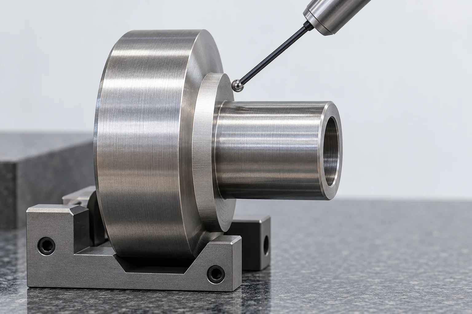
A pair of diameter readings cannot by itself establish that the bore and groove share an axis. Runout, when selected for the functional relationship, is evaluated relative to a datum axis; the specified characteristic and datum setup determine the inspection method. KEYENCE’s metrology guide describes this datum dependence, while the broader tolerances, datums and inspection guide covers how to separate fit size from geometric control. [10] Select the control that reflects what fails in assembly, rather than adding a generic tight number to every cylindrical surface.
Release the finished part, not a machining assumption
The useful turning drawing defines the final material and condition, functional sizes, shoulder and groove geometry, relevant datums, surface or edge conditions, and which end face actually controls length. Its 3D model and 2D requirements must agree. A temporary grip allowance or a proposed process sequence can be discussed with the manufacturer without silently becoming a permanent feature or a drawing tolerance.
For a real shaft or bushing, review any proposed geometry change against the mating part, then test the first grip, the second grip and the inspection state. That connects the design to a feasible route while leaving tool choice and machine selection to the shop’s confirmed capability.
Technical sources
- ASME. Y14.5 – Dimensioning and Tolerancing, 2018 (R2024), public scope. Drawing and model language for geometric requirements.
- Haas Tooling. Lathe Jaws. Jaw contact styles and machinable soft jaws.
- Haas Automation / Trident Machine Tools. Haas Lathe Set-up. Hard and soft jaws in first and second operations.
- Haas Automation. Hydraulic Tailstock – Troubleshooting Guide. Support pressure and stock deformation.
- Sandvik Coromant. External turning. Shoulder, profile and corner-relief tool access.
- Sandvik Coromant. External grooving. Deep- and wide-groove process constraints.
- Sandvik Coromant. Internal turning. Bore diameter, depth, boring-bar size and overhang.
- Haas Tooling. Driven (Live) Toolholders. Axial and radial driven holders and secondary operations on equipped lathes.
- Sandvik Coromant. Parting off. Cutoff stability, pip and burr considerations.
- KEYENCE America. Run-out Tolerance (Run-out Deviation). Datum-axis relationship for circular and total runout.