On this page
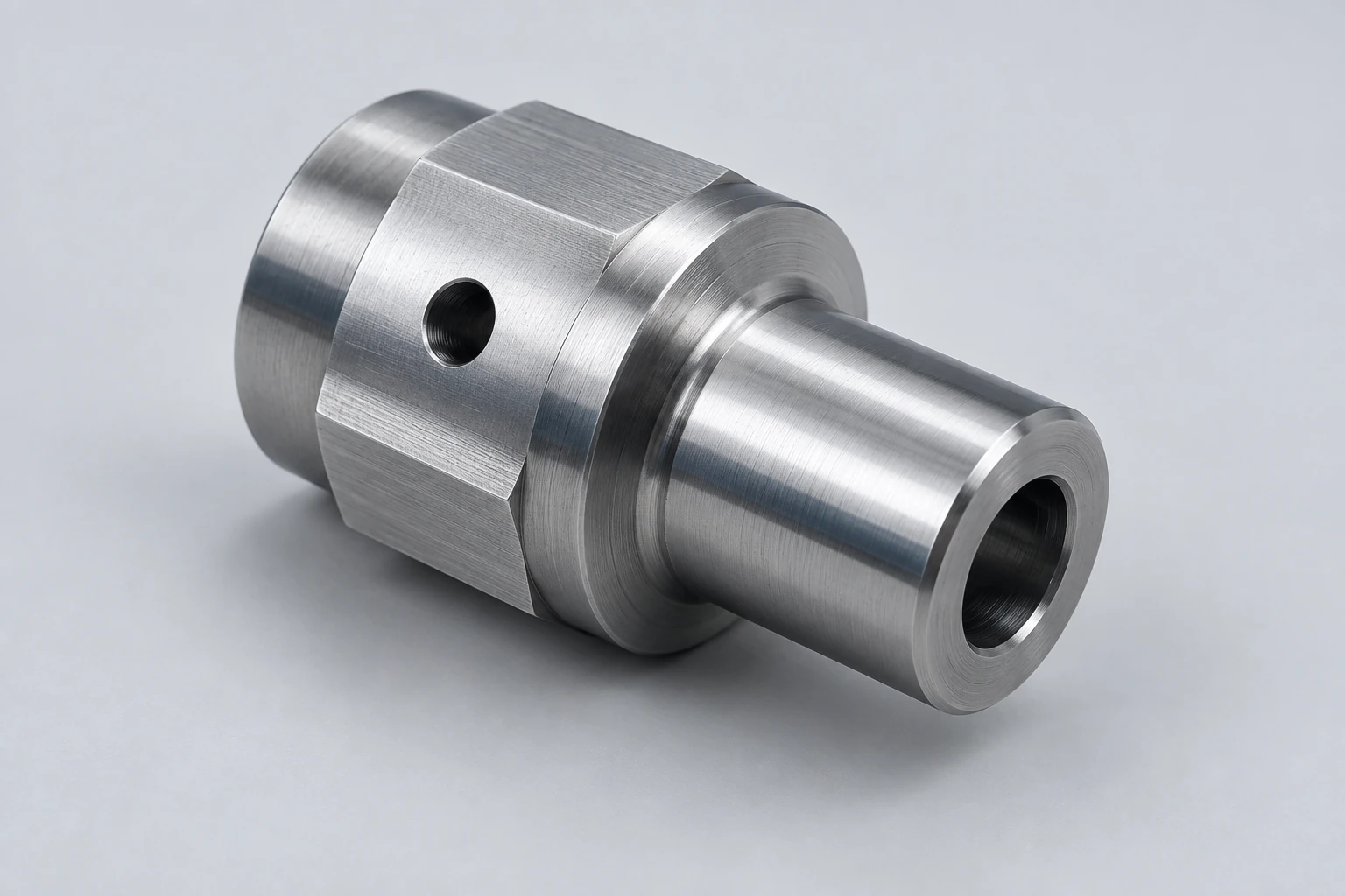
Live tooling lets a lathe rotate a drill, end mill or other driven cutter while the workpiece remains in its workholding. With suitable spindle positioning and axis motion, this adds holes, flats and slots to a turned component. Mill-turn machining combines turning and milling in one machine, but the label alone does not describe its tool access or milling capability.
The key is to separate three things: the direction the tool points, the motion that places it on the feature, and the surfaces available for gripping the part.
The cutting rotation can move from the part to the tool
In ordinary turning, the workpiece rotates and the cutting tool feeds along the required profile. In a typical live-tool drilling operation, the cutter rotates while the workpiece is positioned and held at a selected angle. During some milling paths, controlled workpiece rotation becomes part of the feed motion instead.
A live-tool drive therefore does not replace spindle positioning. It supplies tool rotation; the machine still needs the right way to locate and move the part relative to that cutter. The lathe-versus-mill comparison explains the underlying process difference.
Axial and radial tools approach different surfaces
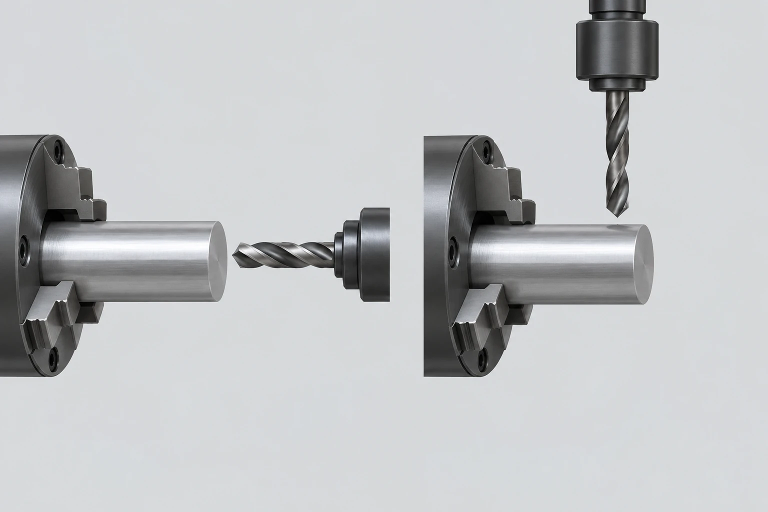
An axial tool points along the spindle axis, toward an end face. A radial tool points across that axis, toward the circumference. These terms describe orientation, not whether the resulting hole is centered, offset, blind or through.
C-axis control governs the workpiece’s angular position. Two uses matter:
- Indexing: move to an angle, hold that orientation for the cut, then reposition for another feature.
- Contouring: coordinate angular motion with linear feed while cutting a path.
A machine that can stop at a commanded angle should not automatically be assumed to support every coordinated milling path. The drive, control functions and installed tools determine the available operation.
| Part feature | Typical tooling | Motion or access to resolve |
|---|---|---|
| Cross-hole aimed toward the shaft center | Radial drill | Axial location and indexed angular position |
| Off-center hole in an end face | Axial drill | Radial offset and angular location, or suitable X–Y positioning |
| Flat along the outside of a shaft | Suitable milling cutter and holder | Cutting path, width, support and orientation |
| Contoured feature on an end face | Axial milling cutter | Compatible X–C interpolation or X–Y motion |
The table identifies questions for the setup; it is not a universal assignment of tools. Holder clearance, tool length and the surrounding geometry can change the approach.
Y-axis motion and a milling head add different capabilities
A Y axis adds a linear direction across the spindle centerline, perpendicular to the usual X–Z plane. It can position a cutter for off-center work and support milling paths that benefit from direct linear motion. It does not follow that every off-center hole requires a Y axis.
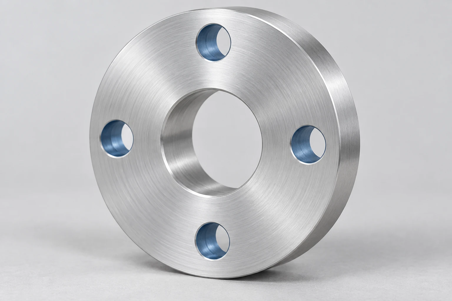
For example, an axial drill can be placed at a bolt-circle radius while the C axis indexes each hole into position, if the configuration permits. For suitable end-face milling, X–C interpolation combines a linear slide with workpiece rotation to generate a path. Haas’s Y-axis training manual explicitly demonstrates an X–C example that does not require a physical Y axis. That is a supported control function, not a promise that every contour is practical without Y.
A turret carrying driven holders is also different from a machine with a dedicated milling spindle. Some mill-turn arrangements add a swiveling milling head, a tool magazine or additional tool systems. Mazak’s INTEGREX i-500 family illustrates a milling-spindle arrangement with B-axis control and several spindle/turret configurations. Those features belong to the specified machine configuration; they are not implied by every “mill-turn” description.
For a proposed route, identify the actual tool direction and coordinated movements. The guide to what machine axis counts mean explains why a large total does not establish what one cutter can do.
One machine can still use two grips
Live tooling cannot reach a surface buried inside the chuck. A secondary, or subspindle, can receive a suitable part and expose its previously held end for further work. The transfer introduces another grip, even when everything happens inside one machine.
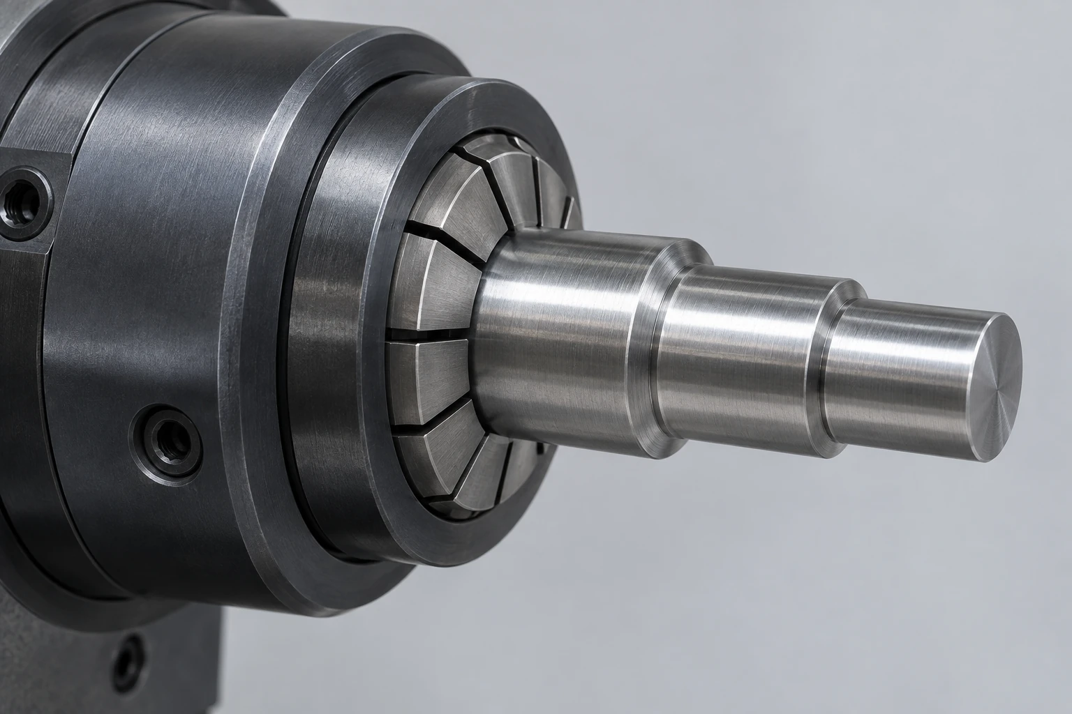
Consider an adapter with turned diameters, a radial port and a rear sealing face. The exposed diameters and port may be machined in the first grip. Finishing the rear face then requires another way to hold the component. The receiving grip must avoid damaging finished surfaces, and the required relationship between the rear face and the locating diameter still needs verification.
That is why “complete on one machine” and “complete without reclamping” are different statements. In a CNC turning review, identify the features made in each grip and the surfaces used to locate them. If a transfer cannot provide adequate support or access, a separate setup may remain the sensible route.
Frequently asked questions
Does drilling a centered hole on a lathe require live tooling?
No. A stationary drill can make a centered axial hole while the workpiece rotates. Live tooling becomes useful for other arrangements, including drilling at selected positions while the part is held angularly. The word “drilling” alone does not identify which member supplies the cutting rotation.
Is a live center the same as a live tool?
No. A live center is a rotating workpiece support, commonly used at the tailstock. Live tooling drives a cutting tool. A lathe equipped with a live center does not thereby gain powered milling or cross-drilling capability.
Can live tooling cut threads?
Suitable driven tooling can support tapping or thread milling when the machine, holder, synchronization and toolpath are compatible. This differs from ordinary single-point turning of a thread. Specify the thread form and useful engagement length; the manufacturing route determines the tool and motion.
Technical sources
Haas Automation, Lathe Operator’s Manual, Next Generation Control, revision U, December 2024: C-axis, dual-spindle and live-tooling sections; Y-Axis Lathe Applications Training, revision D: X–C interpolation example. Haas, 4000-rpm Live Tooling with 12-Station BMT65 Turret and C Axis, and Mazak, INTEGREX i-500, provide configuration examples. Royal Products, Royal Live Centers, and Sandvik Coromant, Deep Hole Drilling Catalogue, clarify workpiece support and drill rotation. These references describe their manufacturers’ equipment, not a VETCNC equipment list.



