On this page
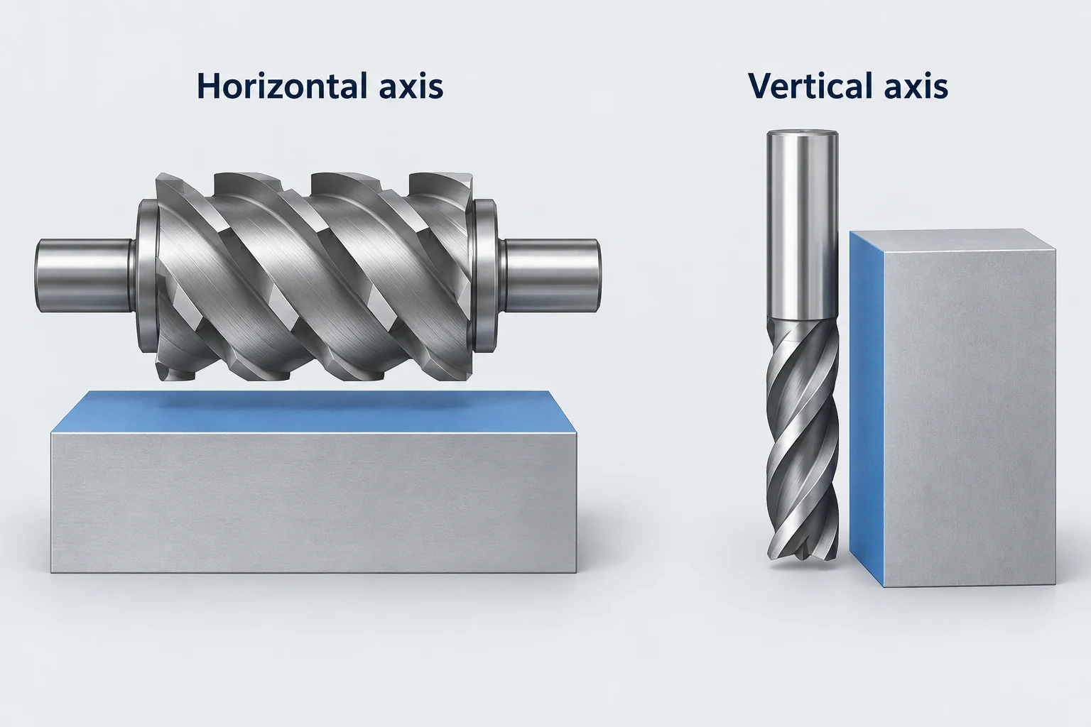
Peripheral milling removes material with cutting edges around the outside of a rotating cutter. For a straight cylindrical cutter generating a flat surface, that surface lies parallel to the cutter axis. The same principle can produce a horizontal plane with a horizontal cutter or a vertical wall with an upright end mill. [1]
“Peripheral” refers to the cutter’s cutting region. It does not restrict the process to the outside perimeter of the workpiece. Internal walls can be machined by the same side-cutting action.
Follow the cutter axis and the surface it generates
In the classic slab or plain-milling arrangement, a cylindrical cutter rotates on a horizontal axis while relative feed carries its peripheral teeth across the workpiece. Its width spans the surface being cut. In end-mill side cutting, the cutter stands beside a wall and its peripheral edges generate that wall as the tool and workpiece move relative to each other.
The machine may move the table, the spindle assembly or a combination of axes. What defines the cutting relationship is their relative motion and contact, rather than which assembly happens to travel.
Face milling has a different relationship: the cutter axis is perpendicular to the principal face being generated. A shoulder cut can combine face and peripheral cutting to create a ledge and wall together. [2] The CNC milling guide explains how these operations fit into a complete machining sequence.
Inside walls and outside profiles can use peripheral cutting
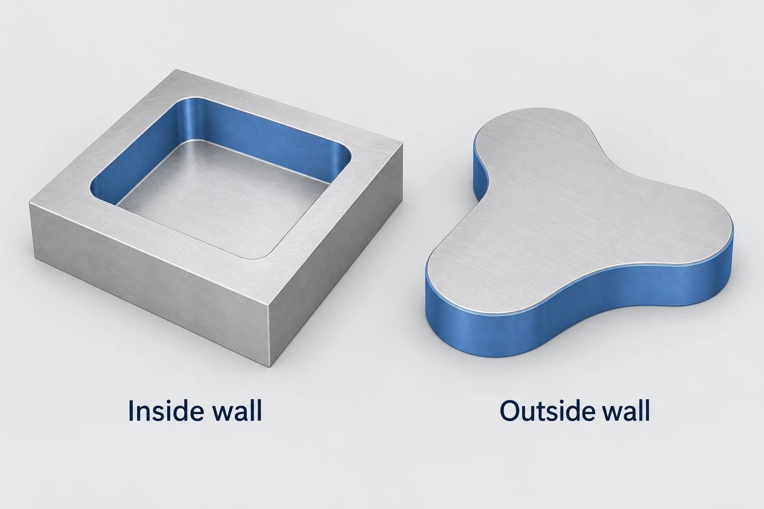
An outside contour gives the cutter open space on one side of the finished wall. A pocket places the cutter inside a boundary, where the opposite wall, corners and remaining stock can restrict movement. The cutting region can still be the side of an end mill in both cases.
For example, a guide block may need its outside sides squared and an internal recess sized for a mating insert. Both tasks can involve peripheral cutting, but their tool access and engagement differ. The smaller internal opening may limit cutter diameter even when a larger tool can reach the exterior.
In a slot or shoulder, the cutter’s end may also remove material. Calling the operation peripheral milling describes the relevant side-cutting action; it does not mean the end edges must be inactive throughout the entire route. [3]
Suitable parts have accessible surfaces and support for the cut
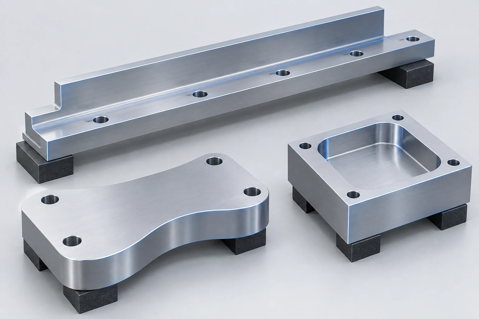
Start with the feature, then consider the holding arrangement. A component does not have to be a particular industry part to benefit from peripheral milling.
| Part feature | Typical cutting arrangement | Main constraint |
|---|---|---|
| Open plane on a block or rail | Slab cutter across the exposed face | Cutter access and work support |
| Straight shoulder on a guide rail | End-mill side edges along the wall | Reach and remaining wall stiffness |
| Outside outline of a plate | Peripheral edges following the boundary | Holding space as the outline is completed |
| Internal wall of a pocket | End mill moving inside the opening | Opening width, corners and holder clearance |
The same feature can admit more than one route. A broad face might be produced by slab milling or face milling, depending on access, equipment and the required result. The process name alone does not establish which will be faster or more accurate for that job.
Tool reach and engaged length are separate decisions
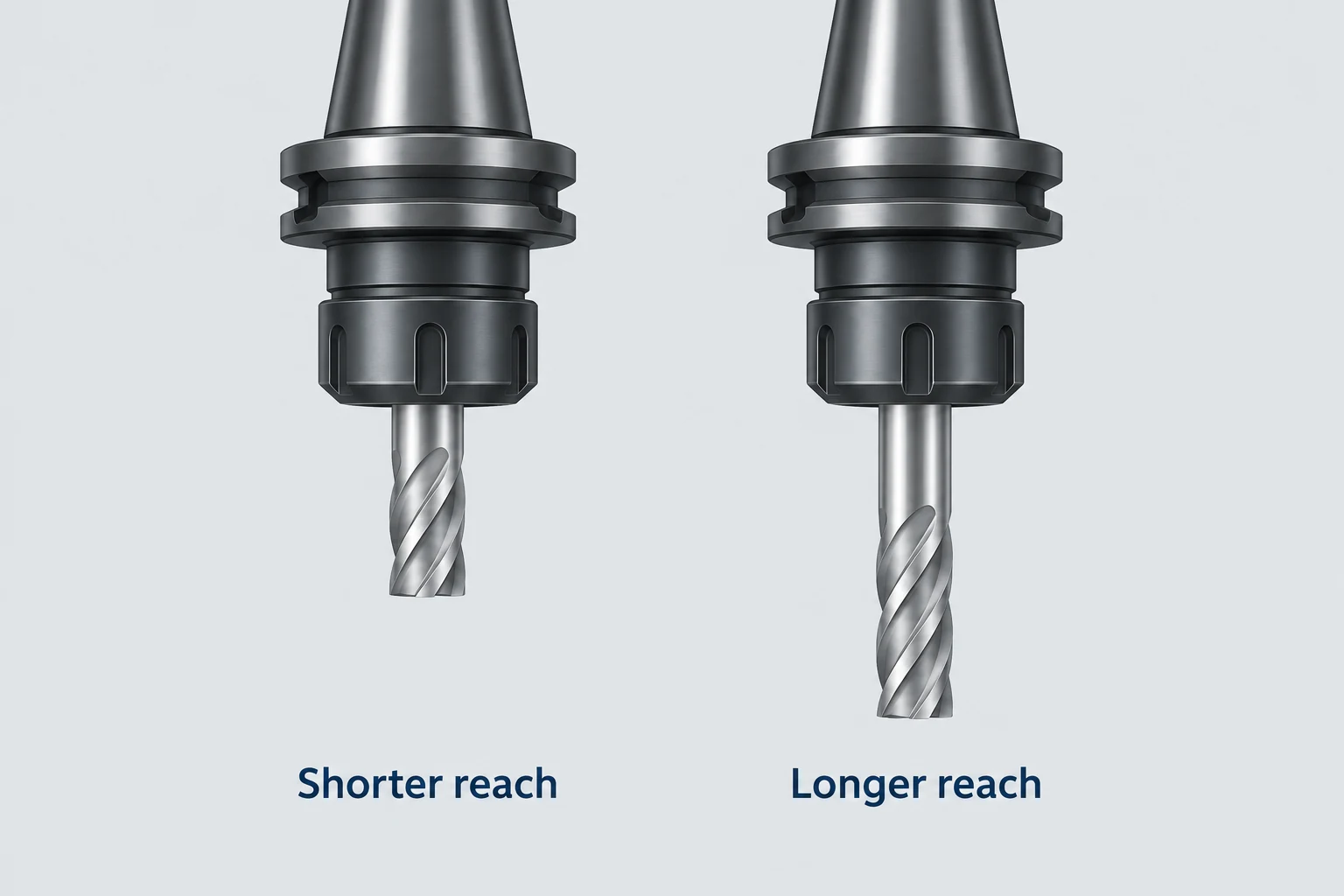
Tool overhang is the unsupported length projecting from the holder. Engaged cutting length is the portion working against the material. A long tool can make a shallow cut, and a deep wall can engage a substantial length of cutting edge. These conditions do not impose the same load or stiffness problem.
A linear, small-deflection cantilever-beam model illustrates why reach matters. For an ideal uniform beam, rigidly fixed at one end and carrying the same transverse force at its free end, tip deflection is proportional to the cube of its unsupported length. Doubling that length gives 2³ = 8 times the model’s deflection when material and cross-section are unchanged. [4]
A real milling system also includes flutes, holder and spindle compliance, changing cutting loads and the workpiece itself. [6] The model explains sensitivity to reach; choosing a tool still requires the actual assembly and cut.
Work support matters on the other side of the contact. As a pocket is opened, its walls or base may become easier to deflect. Cutting a long side wall in one pass can expose more edge to the material, while staged passes change the contact and may leave transitions. Sandvik’s shoulder-milling guidance discusses these depth and support choices. [2] No single pass count suits every wall.
Check internal corners, full assembly clearance and the holding surface
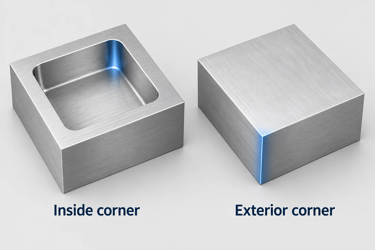
An internal corner constrains the cutter. A rotating cylindrical cutter leaves a radius in a conventional pocket corner. A smaller specified radius can force a smaller tool into a feature that still requires substantial reach. An accessible exterior corner does not impose the same enclosing-radius limit. Any proposed relief, radius change or alternative operation must preserve the approved part geometry. [5]
The holder needs access too. A flute diameter that fits into a pocket does not prove that the neck, holder and spindle-side assembly can clear the surrounding part or fixture. Review the complete assembly along its intended route. [7] The machining materials and design guide develops these corner, depth and wall-access questions.
Keep material available for holding until it is no longer needed. Finishing the outer sides of a plate can remove the very surfaces used to grip it. The route may need a different holding surface, shaped jaws or a planned second setup. Clamping and cutting forces must be considered together.
For a peripheral-milled feature, the useful starting information is its surface geometry, reference features, access and finished requirements. Our CNC milling service provides the relevant context for reviewing those features and the holding sequence.
Peripheral milling FAQ
Is peripheral milling only done on a horizontal machine?
No. Horizontal slab milling is a familiar arrangement, but the side edges of an upright end mill can perform peripheral cutting on a vertical wall. Identify the cutting region and generated surface, rather than relying only on machine orientation.
Does peripheral milling mean machining the outside of a part?
No. The term refers to the cutter’s periphery. An internal pocket wall can also be machined using the peripheral edges of an end mill.
Is peripheral milling the same as climb milling?
No. Peripheral identifies the cutting region. Climb and conventional describe the relationship between rotation and feed at the cut. A peripheral operation still needs an appropriate feed-direction strategy.
Can a smaller end mill solve every access problem?
No. It may fit a tighter internal radius, but the required reach, tool stiffness, holder clearance and chip space still need attention. A smaller cutting diameter alone does not establish a workable route.
Technical sources
- NPTEL. Design for Machining: Milling Operations, Module 3, Lecture 5. Peripheral and face-cutting geometry.
- Sandvik Coromant. Shoulder milling. Peripheral and face contact, deep shoulders and thin-wall support.
- Sandvik Coromant. Milling holes and cavities/pockets. Internal shoulders and pocket access; used with the shoulder-milling guidance above.
- MIT OpenCourseWare. Deflections due to Bending, Engineering Mechanics for Structures, Chapter 10, p. 268. End-loaded cantilever model.
- Sandvik Coromant. Milling inside corners. Corner radius and cutter engagement.
- Sandvik Coromant. How to reduce vibration in milling. Tool overhang, holder rigidity and workpiece support.
- Autodesk Fusion Help. Shaft and Holder Modes reference. Clearance around the shaft and holder.



