On this page
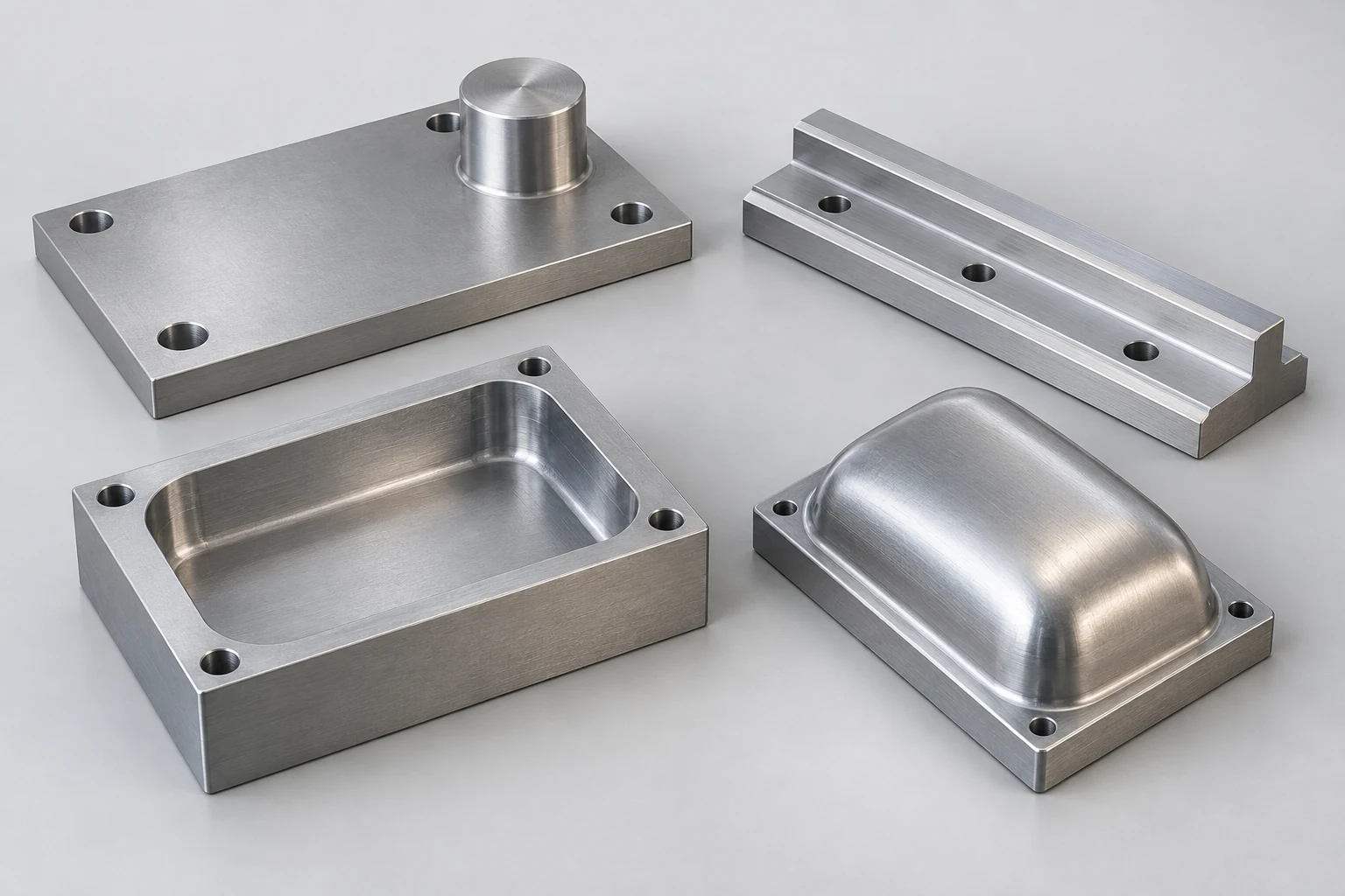
Face, end, pocket and profile milling describe different aspects of a cut. Face milling produces a broad face; end milling uses an end mill; pocket milling removes material inside a boundary; and profile milling follows a contour or shaped surface. The names overlap. An end mill can finish a pocket wall, machine a shoulder or follow an outside profile.
Finishing milling removes the remaining material needed to bring a surface to its specified condition. The final pass for a plate face has different demands from the final pass around a pocket. The examples below show how to choose that finishing task. For the overall cutting sequence, see how CNC milling works.
Face milling: finish the open plane without losing its geometry
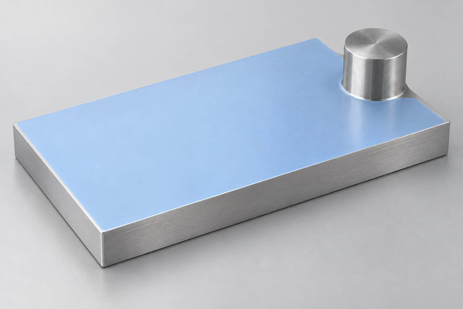
Consider a tooling plate with a broad top face and a raised locating boss. A face mill can sweep the open area efficiently, but its cutting envelope and body must clear the boss. A smaller tool or a separate path may be needed near the obstruction. Cutter diameter alone does not settle access.
The finishing cut must produce the required face while the plate is supported. Insert setting, cutter runout and cutting forces can affect the result. A repeated pattern across the surface may relate to how the cutting edges sit and overlap, rather than simply to excessive feed.
Sandvik Coromant describes wiper inserts as one option for improving face-milled texture. Their wider finishing land and correct setting matter; a wiper is not a general cure for an unstable setup. The cutter manufacturer’s application conditions still apply. [1]
If the face supports another component, its flatness and its relationship to the opposite face may matter as much as its appearance. A shiny surface does not establish either requirement.
End milling: distinguish the wall from the adjacent floor
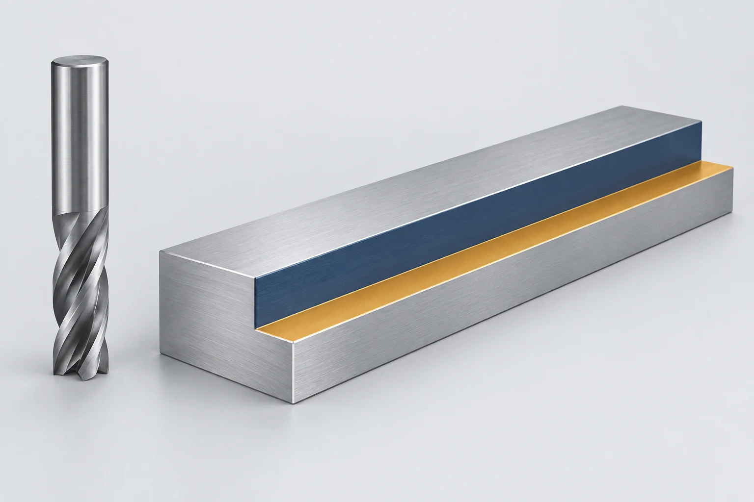
A stepped guide rail presents a vertical shoulder beside a horizontal ledge. A suitable end mill can use its peripheral cutting edges along the wall and its end geometry on the ledge. It may cut both in one operation, but the two surfaces do not automatically have the same finishing needs. Sandvik’s shoulder-milling guidance treats the combined wall-and-face relationship explicitly. [2]
Suppose the rail guides a sliding block against its side, while the ledge supports the block from below. Wall location controls one part of the fit; ledge height and the relationship between the surfaces control another. These requirements should be visible in the process plan, even if one cutter produces both surfaces.
A tall shoulder introduces more tool reach. Finishing the full wall height can avoid transition lines between depth levels, but it also increases the engaged cutting length. Several depth passes may improve the load situation while creating transitions that need attention. The choice depends on the cutter, remaining stock and rigidity, rather than a rule that one pass always finishes better.
For a thin rail or wall, the remaining workpiece also needs support as material is removed. A finishing path calculated around a rigid model does not account for every possible movement of the real part.
Pocket milling: manage the floor, walls and corners separately
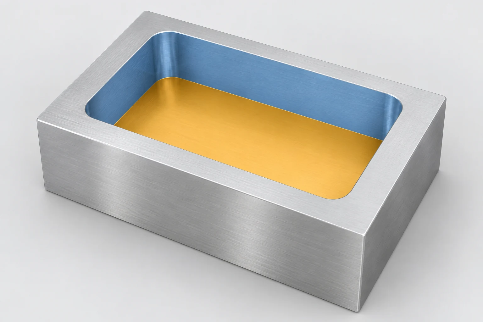
In a recessed mounting block, the pocket floor may establish seating depth while the walls locate an inserted component. Roughing can leave material for later passes on both surfaces. Radial stock is left beside the tool, such as on vertical walls; axial stock is left in the tool-axis direction, such as above a horizontal floor. Autodesk’s CAM documentation exposes these as separate controls. They need not be equal. [3]
This distinction makes the finish plan more specific. A wall-finishing pass can address the pocket boundary without being asked to remove the full remaining floor allowance at the same time. A floor pass can then be planned around depth, support and the required texture. The actual order depends on which material provides support and which surfaces establish the part’s location.
Internal corners need their own check. A large roughing cutter can leave more material in a corner than along a straight wall. Sending a finishing cutter through that area can increase engagement abruptly. Rest machining removes material left by an earlier tool; it can prepare the corner before the final wall pass. Tool diameter and the specified corner radius must still be compatible. [4]
The materials and design guide connects pocket access, internal radii and wall geometry with the part’s functional requirements.
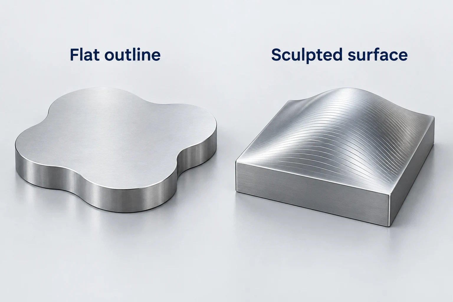
Profile milling: separate a flat outline from a sculpted surface
A flat cam plate can have a curved outside outline while retaining a constant thickness. An end mill’s side edges can follow that perimeter. The task is to control the outline, wall condition and transitions where curvature changes. [7]
A domed die insert presents a different task: its surface height and slope change across the part. A ball-nose or other suitable radius cutter can build the shape through adjacent passes. The tool’s contact region and the spacing between passes influence the small ridges, or cusps, left on that surface. [5]
On a fixed surface with the same cutter geometry, closer pass spacing generally reduces the geometric cusp left between paths. [8] That does not, by itself, remove marks caused by vibration, runout or a damaged cutting edge. Nor is a programmed cusp height an inspection result for Ra, the arithmetic mean roughness parameter. Ra describes a measured surface profile under defined evaluation conditions. [6]
The flat plate therefore needs a perimeter-finishing strategy; the die insert needs a surface-finishing strategy that follows its changing shape. Calling both operations “profiling” does not make their tool contact equivalent.
Prepare the material that the finishing tool will actually encounter
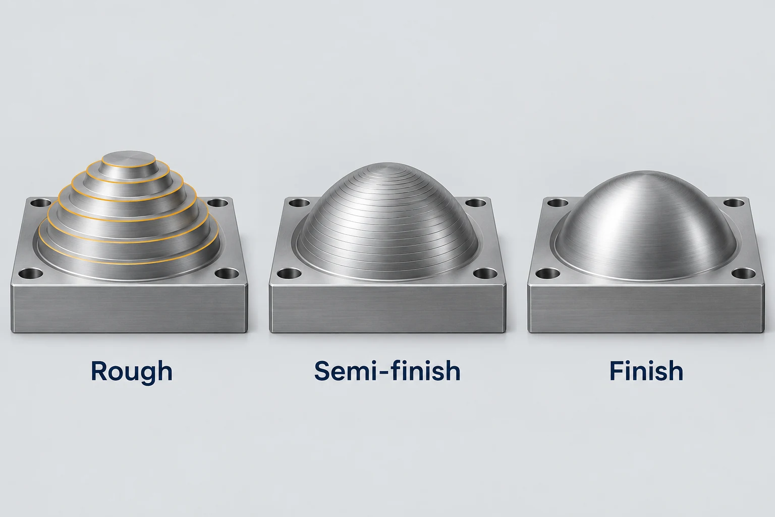
Roughing is organized around removing stock. Finishing is organized around the surfaces that remain. Between them, semi-finishing can make the remaining allowance more consistent. On a sculpted part, coarse roughing terraces can leave a finishing tool alternating between light contact and heavier cuts. Preparing that material reduces the variation the last pass has to handle. [5]
An allowance is material deliberately left for another operation. It is not the permitted error in the finished part. Its amount and distribution depend on the material, tool, feature and preceding operations. A single allowance value copied across every face, wall and pocket does not describe a complete finish plan.
| Surface | Prepare before finishing | Check on the finished part |
|---|---|---|
| Open plate face | Accessible stock and stable support | Face geometry and specified texture |
| Shoulder wall and ledge | Wall allowance, reach and remaining support | Location, height and angular relationship |
| Pocket floor and walls | Separate floor/wall stock; corner remnants | Depth, boundary size and corner geometry |
| Sculpted profile | Consistent residual stock and suitable pass spacing | Surface shape and specified texture |
The table identifies questions for the route; the drawing determines which characteristics need acceptance checks. Visible marks alone cannot establish size, flatness or profile accuracy. Equally, a dimensional result does not establish a separately specified surface-texture requirement.
For a drawing review, identify the functional surfaces and their finished requirements before assigning a blanket “fine finish” to the entire component. Our CNC milling service is the relevant place to discuss those requirements together with tool access and the proposed machining route.
Milling and finishing FAQ
Can the same end mill face, pocket and profile a part?
It can perform several of these tasks when its geometry, reach and cutting conditions suit them. That does not mean one tool diameter or one toolpath is the best choice for every surface.
Do pocket walls and floors need the same finishing allowance?
No. Wall and floor allowances address different directions and surfaces. Their values and finishing sequence should suit the cutting loads, support and final requirements.
Does a smaller stepover guarantee a better surface finish?
It can reduce geometric cusps for the same cutter and surface, but it does not cure every source of poor finish. Tool condition, vibration and actual contact still matter, and a texture requirement needs the appropriate measurement.
Is finish milling the same as anodizing or polishing?
No. Finish milling removes material with a milling cutter. Anodizing and polishing are different operations with their own effects on the surface. When later processing affects a functional feature, specify the required final condition.
Technical sources
- Sandvik Coromant. Face milling, including finishing with wiper inserts. Cutter setup, runout and finishing conditions.
- Sandvik Coromant. Shoulder milling. Combined side-and-face cutting, deep shoulders and thin-wall support.
- Autodesk Inventor CAM Help. 2D Pocket, “Radial (wall) stock to leave” and “Axial (floor) stock to leave.”
- Sandvik Coromant. Milling inside corners. Corner contact and cutter-load changes.
- Sandvik Coromant. Profile milling. Constant stock and generation of sculptured surfaces.
- NIST. NIST Surface Roughness and Step Height Calibrations, Measurement Conditions and Sources of Uncertainty; Height Parameters. Surface-profile parameters and measurement conditions.
- Autodesk Fusion Help. 2D Contour reference. Boundary following, rest machining and finishing controls.
- Autodesk. Scallop height (FeatureCAM Help) and Scallop Finishing reference (Fusion Help). Between-pass geometry and spacing.



