On this page
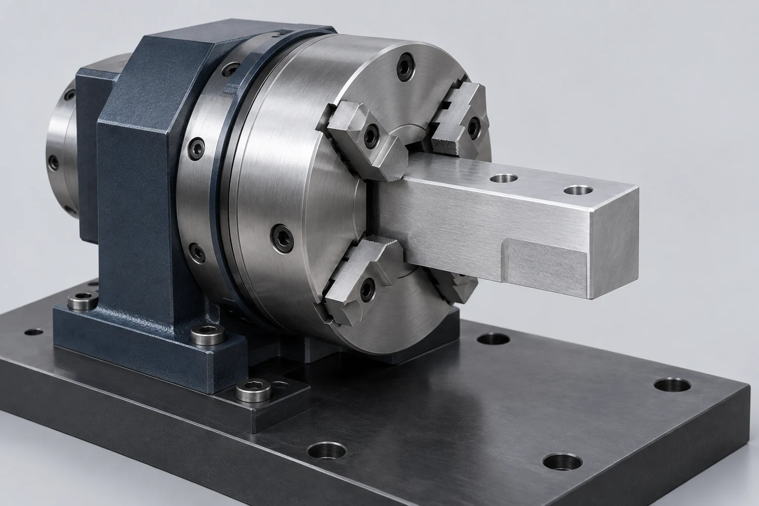
A fourth-axis setup needs more than a secure grip. It needs a known centerline, an axial position and, when new features must align with existing geometry, a known angular orientation. The holding arrangement must preserve those references while leaving room for cutting, rotation and any end support.
Start with the surfaces that locate the finished part in its assembly. Then decide which can also locate the machining operation, which can accept contact and which must remain accessible. The comparison of three-, four- and five-axis machining explains the available motion; here, the task is making a single rotary setup usable.
Locate the centerline, length and starting angle
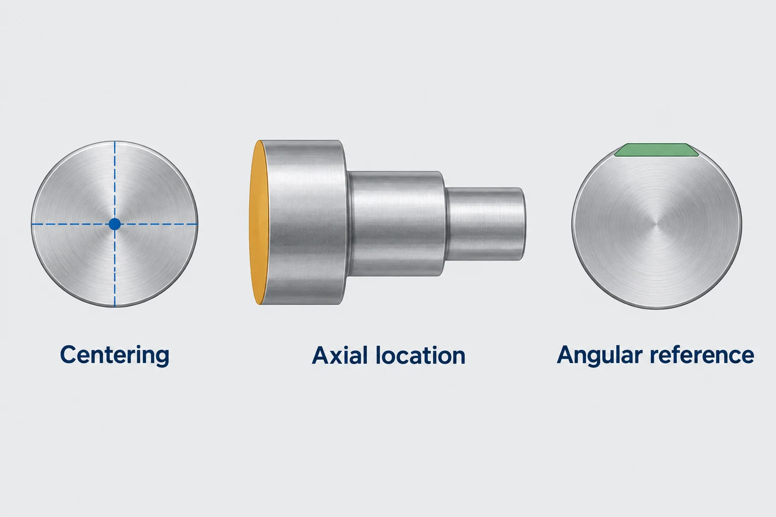
Consider a shaft that already has a bearing journal, a shoulder and a flat, and now needs radial holes. Three separate locating questions determine how those holes relate to the existing features:
- Radial centering: which cylindrical surface or other reference places the required part axis on the rotary centerline? Gripping an outside diameter does not prove that a different functional bore or journal is concentric with it.
- Axial location: which end face or shoulder seats against a stop? A varying insertion depth moves the hole pattern along the shaft even if the part is well centered.
- Angular orientation: which flat, keyway, hole or fixture locator establishes the starting angle? This is often called clocking. A round grip alone does not identify the angular position of an existing flat.
Locators establish the intended position; clamping holds the part against them and resists the machining loads. Carr Lane’s Locating & Clamping Principles treats these as separate functions. [1]
A rotationally symmetric blank may need no particular starting angle for its first feature. Once another feature must align with that feature, the angular relationship matters. Setting the rotary display to zero cannot resolve an unknown part orientation.
Choose the holder around usable references
A chuck, collet and dedicated fixture solve different contact problems. Compare them against the actual locating features and cutting loads, rather than assigning one a universal accuracy advantage.
| Holding approach | Useful starting geometry | Location still to establish | Access consumed |
|---|---|---|---|
| Chuck with suitable jaws | A cylindrical grip, prepared boss or profile that the selected jaws can hold | Jaw alignment to the required axis; axial stop; clocking of existing features | Gripped length and space around the jaw ends |
| Collet matched to the stock | A compatible round or specially shaped grip section within the collet’s specified range | Consistent seating against a suitable stop; angular reference where needed | The enclosed grip section and nearby shoulder clearance |
| Dedicated rotary fixture | An irregular part with usable bores, mounting features or locating faces | Defined contacts tied to drawing references; restraint against cutting loads | Space occupied by the fixture body, locators and clamps |
Tormach’s fourth-axis manual documents chuck, collet and fixture-plate arrangements; each depends on a compatible mounting and locating interface. [7]
Collet closure can affect axial seating. Royal Products’ CNC collet-chuck guide illustrates the distinction between pullback designs and designs intended to maintain axial position during closure. Check how the selected mechanism locates the part and works with its stop. SCHUNK’s soft top-jaw guidance likewise ties jaw machining to the required gripping diameter. [2] [6]
A dedicated fixture can use functional references that are more useful than the outside stock shape. It can also become the largest rotating object in the setup; include the fixture in the clearance review.
Support the exposed length without losing needed access
A long exposed section can need support beyond the chuck. A tailstock center is one option when the part has a suitable center hole and the arrangement allows that end contact. The center must align with the rotary axis; adding support does not correct an incorrectly located grip.
Haas’s tailstock instructions treat alignment and applied force as setup requirements. Their pressure and extension limits belong to the specified equipment. Part length alone is not enough to select a universal tailstock force or unsupported span. [3]
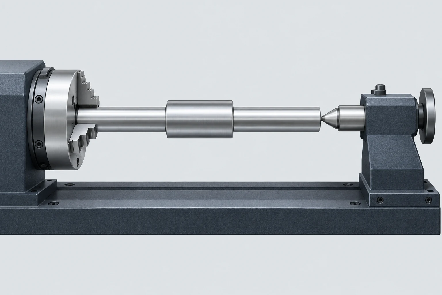
Keep that occupied space in the feature plan. An axial end hole, a face requiring finishing or a surface that cannot retain a center hole may need another support arrangement or a later operation. Moving the tailstock away also changes support during that operation.
If milling leaves a thin neck or wall between the supports, review the remaining structure as well as the original blank. The materials and part-design guide connects wall stiffness and clamping to the condition in which finished dimensions are checked.
Check the corners through the whole rotation
A rectangular section can clear the table while lying flat and strike it while turning. Its corners travel farther from the centerline than the middle of a side. For a centered rectangle making a full turn, the part’s swept diameter equals its diagonal, not its width or height.
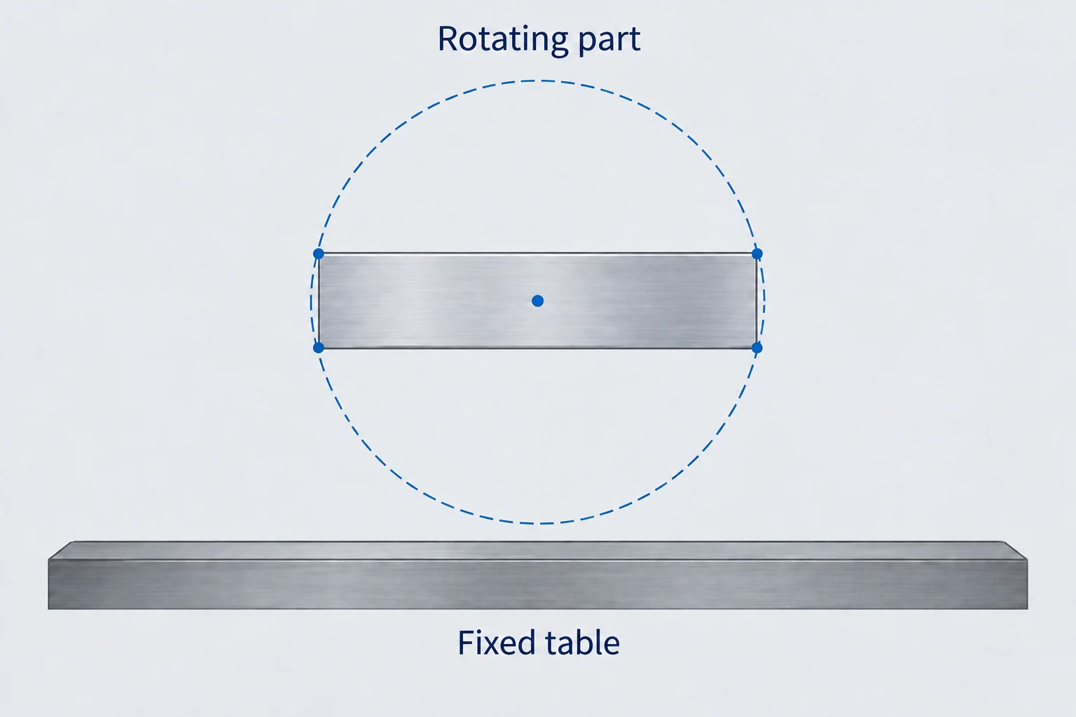
Use the actual rotation range and include the blank before material is removed. Then add everything that turns with it: projecting jaws, clamp screws, fixture plates and any eccentric mounting. Check the route between indexed positions as well as the positions where cutting occurs. Haas’s rotary workholding guidance explicitly calls for a fully seated workholding device and rotation without interference. [4]
The tool and holder add a separate moving envelope. A verification model should represent the relevant machine motion, current stock and fixture geometry. Autodesk distinguishes simulation with a machine model and its kinematics from tool-and-stock simulation; watching an animation alone is not the collision-check result. [5]
Define contact zones before finishing the journals
On a stepped shaft, three contact zones deserve separate decisions. [1]
- Sacrificial grip extension: It can accept jaw impressions if the marked material is removed later.
- Finished bearing journal: Its specified size and surface condition must be preserved.
- Shoulder used as an axial stop: It must seat consistently; a chip or raised contact damage can affect both seating and the finished interface.
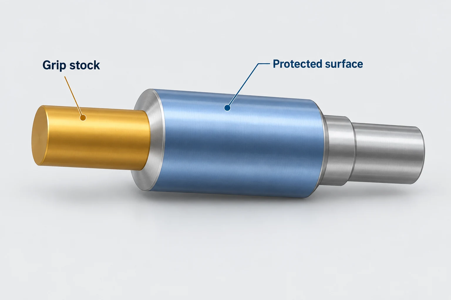
The clocking flat is another contact, even if it carries little clamping load. Decide whether its locator may touch the final surface or whether an intermediate feature is needed. “Clamp marks allowed” should identify the permitted region and acceptance condition, not imply permission to damage every gripped surface.
When no contact marks are allowed on the available grip, review contact geometry, load, cleanliness and the finishing sequence. Simply substituting soft jaws does not establish an acceptable result. If the grip extension is removed in a later setup, preserve a usable axial and angular reference for any remaining features.
For a part-specific review, the useful information is the drawing’s functional references, acceptable contact zones, end features and final surface requirements. VETCNC’s CNC milling service provides the next step for discussing those requirements with the complete part geometry.
4th axis workholding FAQ
Does a self-centering chuck establish the part’s starting angle?
No. Centering a compatible outside profile and clocking an existing feature are different tasks. A round part with a flat or keyway needs an angular reference when the new features must align with it.
Is a collet always more accurate than a chuck?
No universal ranking establishes the finished result. The grip geometry, locating surfaces, holder condition, alignment, loads and seating all matter. Compare the proposed setup against the part’s required relationships.
Does every long part need a tailstock?
No single length rule applies. Section stiffness, exposed length, cutting loads and available contact geometry determine the support requirement. A tailstock is one option, and its contact must remain compatible with the end features.
Can all clamp marks stay on the finished part?
Only where the agreed requirements permit them. Distinguish removable grip stock from finished journals, locating shoulders, sealing faces and appearance zones. A visually small mark can still be unacceptable on a functional interface.
Technical sources
- Carr Lane Manufacturing. Locating & Clamping Principles for Jig & Fixture Design. Locating functions, support, contact and part distortion.
- Royal Products. Royal CNC Collet Chucks. Grip shapes, collet fit and pullback versus fixed-length arrangements.
- Haas Automation. Rotary/Tailstock — Operator’s Manual Supplement, Tailstock — Operation/Setup. Alignment, support and equipment-specific force requirements.
- Haas Automation. Rotary — Workholding, Section 7.6. Seating and interference checks.
- Autodesk Fusion Help. Simulation for manufacturing. Machine models, kinematics, collision checks and verification.
- SCHUNK. Soft top jaws. Machining the jaw contact to the required clamping diameter.
- Tormach. 4th Axis Installation Manual — 6 in. and 8 in. 4th Axis for M/MX. Workholding arrangements and compatible locating interfaces.



