On this page
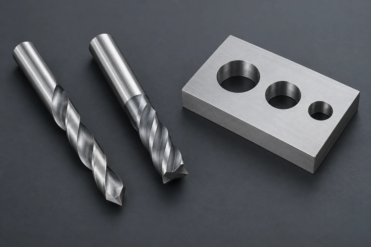
Drilling and milling can both produce a round hole, but they generate it differently. A drill advances along the hole axis, with its cutting diameter establishing the nominal hole size. In circular hole milling, a smaller cutter moves around the hole center; helical milling adds downward travel to that circular motion. The choice depends on diameter, bottom shape, entry and exit surfaces, depth, and the finished requirements.
A milling machine can perform either operation. The distinction is the tool and its cutting path, not the machine’s name. Our guide to how CNC milling works explains that broader relationship.
Compare the cutting motion and entry method
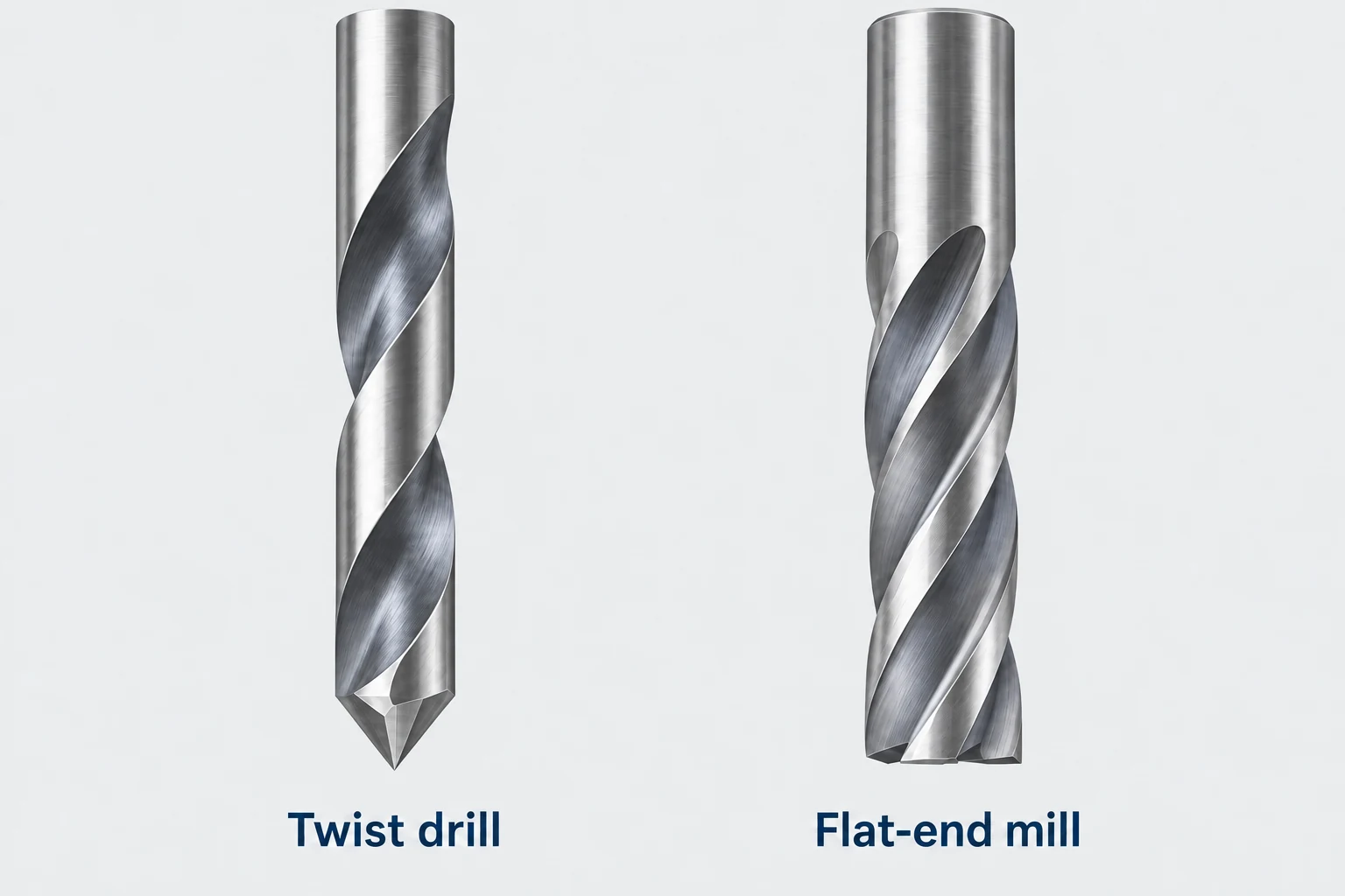
In ordinary drilling, the rotating drill feeds axially into the material. The cutting end opens the hole, while the flutes provide a route for chips to leave. A conventional twist drill is designed for this axial operation; it should not be treated as an end mill for enlarging the hole sideways.
For a milled hole, the cutter rotates about its own axis while its center travels around the hole axis. A circular pass at one depth can machine the wall of an existing opening. A helical path combines circular movement with axial advance, allowing a suitable cutter to enter or enlarge a hole progressively. [1]
The entry method must suit the cutter. Straight plunging requires appropriate center-cutting geometry. Ramping also has tool-specific limits; an unsuitable cutter and hole combination can leave an uncut central core that interferes with the tool. A predrilled entry may be needed. [1] [2]
Hole diameter follows either the tool or the toolpath
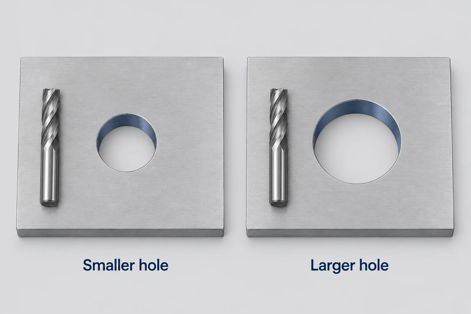
A drill’s diameter largely fixes the nominal hole it produces. Changing the required diameter usually means selecting another drill or adding an enlargement or finishing operation.
In circular milling, the hole is wider than the cutter. For ideal cylindrical geometry, the tool-center path radius is (hole diameter − cutter diameter) ÷ 2. Increasing that path radius produces a larger boundary with the same cutter. This is why milling can be useful for several hole sizes when changing dedicated tools would be inconvenient. [3]
Consider a plate with repeated clearance holes and a larger locating recess. The repeated holes may suit one drill, while the recess may suit a smaller milling cutter traveling around its boundary. A single part can therefore favor different methods for adjacent circular features. The larger diameter alone does not justify replacing every drilled hole with a milled one.
The equation describes the finished wall’s geometry, not a complete entry strategy. It does not establish that the cutter can clear the center, ramp at the chosen pitch or reach the bottom. Nor does changing the programmed diameter guarantee the measured diameter: tool deflection, actual cutting diameter and finishing conditions still matter. [6]
Choose around the hole that must remain
| Hole condition | Route to consider | Condition that can change the choice |
|---|---|---|
| Repeated holes at one available drill size | Drilling | Entry, depth and finished requirements suit the drill |
| Several diameters with accessible, relatively shallow geometry | Circular or helical milling | Cutter, entry path and reach suit each diameter |
| Blind hole with a functional flat floor | Suitable flat-bottom tooling or floor milling | Required floor geometry and corner blend |
| Deep hole through a small opening | Purpose-suited drilling route | Chip evacuation, guidance and usable tool length |
| Closely controlled bore or demanding surface requirement | Creation followed by qualified finishing | Size, form, position and texture must each be addressed |
A small opening may leave insufficient room for a useful circular entry path. At the other extreme, a wide hole may require several clearing passes before its boundary is finished. Compare the actual material-removal sequence, not just the final circle shown in the model.
These are starting points, not a speed ranking. Compare the same material, quantity and final condition, including tool changes and any finishing passes. A drilled starter hole followed by milling can also be a sensible combination. Where boring or reaming enters the route, the machining process comparison explains its separate role.
Separate bottom shape from entry and exit conditions
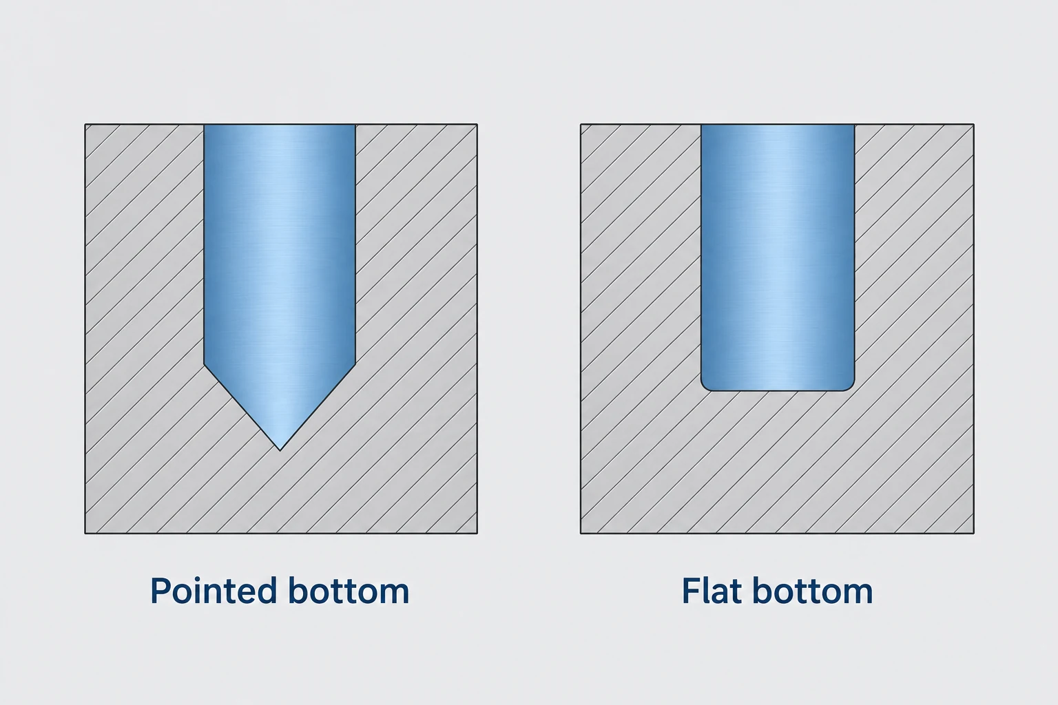
A conventional pointed drill leaves a conical end in a blind hole. Full-diameter depth therefore differs from depth to the drill tip. That distinction matters when a pin needs a stated length of cylindrical engagement or the remaining wall beneath the hole is limited.
A flat floor can be produced with suitable milling or specialized flat-bottom tooling. Simply plunging an ordinary end mill does not guarantee one: end-face dish can leave a non-flat floor. The cutter geometry and a floor-clearing or finishing path must produce the required surface. A flat bottom also does not imply a perfectly sharp wall-to-floor corner; specify the allowed blend where it affects seating. [4]
For a bottom-seated component, distinguish the seating plane from the surrounding cylindrical fit. A component can reach the correct axial depth yet interfere at the corner. Conversely, a pin that never touches the bottom may only need adequate straight-wall engagement and clearance below its end.
The surface at the opening presents another problem. On a slope, curved surface or partial edge, cutting engagement can begin unevenly and a pointed drill may tend to move off its intended entry. A prepared flat or purpose-suited tool may help. An angled exit or intersecting hole changes engagement again; switching to milling does not remove the need to review support and breakout. [4] [7]
Depth changes access and chip evacuation
Two holes with the same opening diameter can need different routes when their depths differ. Drilling needs chips to travel out along the available flute space. Material, chip form and coolant delivery affect that escape; packed or recut chips can damage the tool and hole surface. [5]
Milling leaves clearance around a smaller cutter, but that does not make chip evacuation automatic. A deep blind hole still traps material below the opening. Greater reach also increases the importance of tool rigidity, cutting length and holder clearance. The selected tool’s application data should govern the depth assessment, rather than a universal drill-versus-mill depth limit. [3] [6]
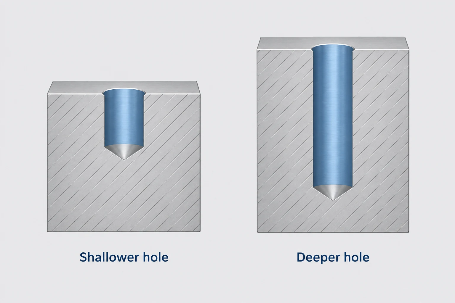
Finally, distinguish making the opening from completing the bore. A finishing pass can adjust a milled diameter, but it cannot by itself prove roundness, location or surface texture. State those functional requirements separately. For a part with related holes, pockets and mounting faces, our CNC milling service provides the next step for reviewing the complete geometry and manufacturing route.
Drilling and hole milling FAQ
Can an end mill drill straight into solid material?
Only when its geometry and application guidance permit that entry. Center-cutting geometry is necessary for ordinary straight plunging, but the material, depth and chip-removal conditions must also suit the tool.
Is helical milling the same as circular milling?
Helical milling adds axial advance to circular movement. A circular pass at fixed depth can machine an existing hole wall; a suitable helical path can progress into the material.
Does a flat-bottom hole have to be milled?
No. Specialized flat-bottom drills and other suitable tools can produce that geometry. The required floor, corner and entry conditions determine the choice.
Is a milled hole always more accurate than a drilled hole?
No. The result depends on tooling, machine motion, support, material and finishing. A controllable toolpath is useful, but the finished diameter, geometry and surface still need to meet their specified requirements.
Technical sources
- Sandvik Coromant. Ramping: two axis linear and circular. Helical motion, entry geometry and center-clearing constraints.
- Harvey Performance Company. Most Common Methods of Tool Entry. Straight-plunge and ramp-entry suitability.
- Sandvik Coromant. Milling holes and cavities/pockets. Conditional reasons to consider hole milling.
- Harvey Performance Company. 10 Reasons to Use Flat Bottom Tools. Drill-point bottoms, end-mill dish and special entry conditions.
- Sandvik Coromant. Drilling a hole. Hole dimensions, chip evacuation and setup considerations.
- Autodesk Fusion Help. Bore reference. Helical pitch, diameter compensation and finishing controls.
- Sandvik Coromant. Irregular surface drilling. Uneven entry and exit, cross holes and tool stability.



