On this page
CNC machining tolerances define the permitted variation in a part’s dimensions and geometry. Fits describe how mating features relate; inspection checks whether the finished part satisfies those requirements. A useful specification connects all three. A bore can have the right diameter and still sit in the wrong place, while an impressive measurement readout can leave the actual acceptance question unanswered.
Precision machining technology includes the cutting process, tooling, workholding and measurement method. None of those replaces a clear definition of the finished part. The practical route is to identify the functional interfaces, assign the necessary size and geometric controls, account for the delivered condition, and choose a suitable verification method.
Start with the surfaces that make the assembly work
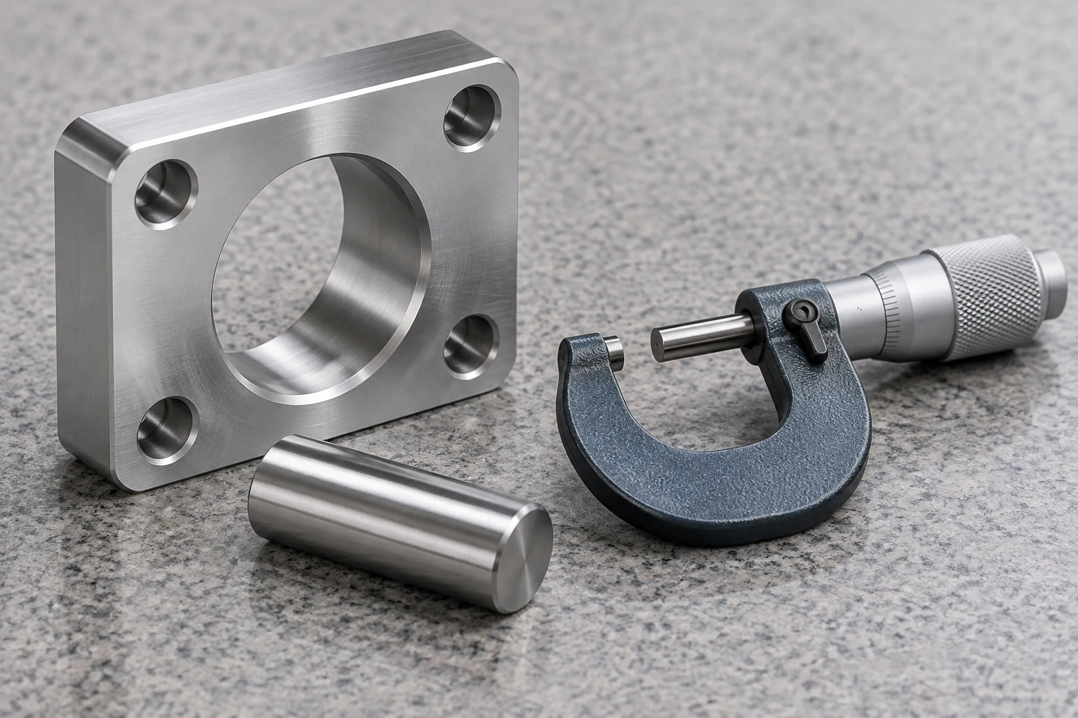
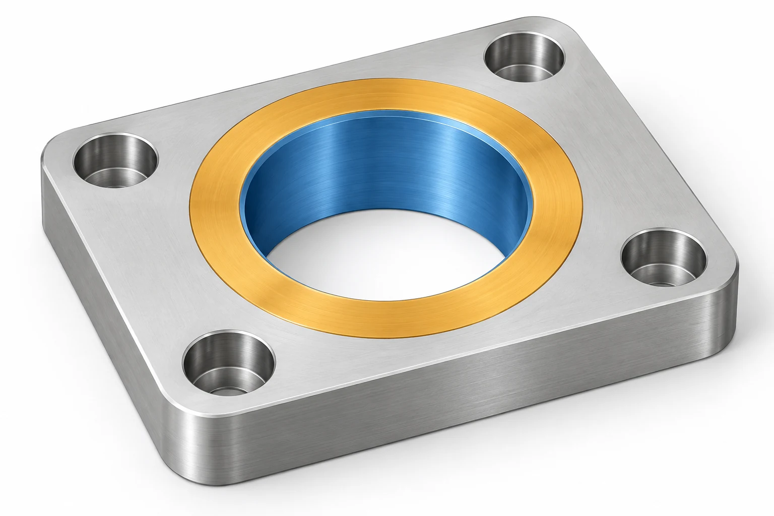
Consider a flange that locates on a cylindrical pilot, seals against a mating face and attaches through a bolt pattern. The pilot fit controls clearance. The sealing face has its own surface and geometric requirements. The bolt holes must align with the mating part. Applying the same plus-or-minus value everywhere does not describe these different jobs.
| Requirement | What it addresses | Example on the flange |
|---|---|---|
| Size tolerance | Permitted size variation | Pilot diameter or plate thickness |
| Geometric control | Form, orientation or location | Sealing-face flatness or hole-pattern position |
| Surface texture | Specified surface-profile characteristics | Roughness on the sealing land |
| Material and finish | Grade, condition and treatment | Alloy, heat treatment, coating and masked areas |
These requirements interact, but they are not interchangeable. Roughness does not establish flatness, and a close diameter tolerance does not by itself communicate every location or orientation requirement. The applicable drawing rules can also relate size and form; read the complete specification rather than treating each number in isolation. ASME Y14.5 defines the GD&T language used on many US engineering drawings. [1]
For an introduction to models, drawing notes and manufacturing sequence, see the CNC machining basics guide. Here, the task is to turn that part definition into limits and checks that protect the assembly function.
Convert the callout into upper and lower limits
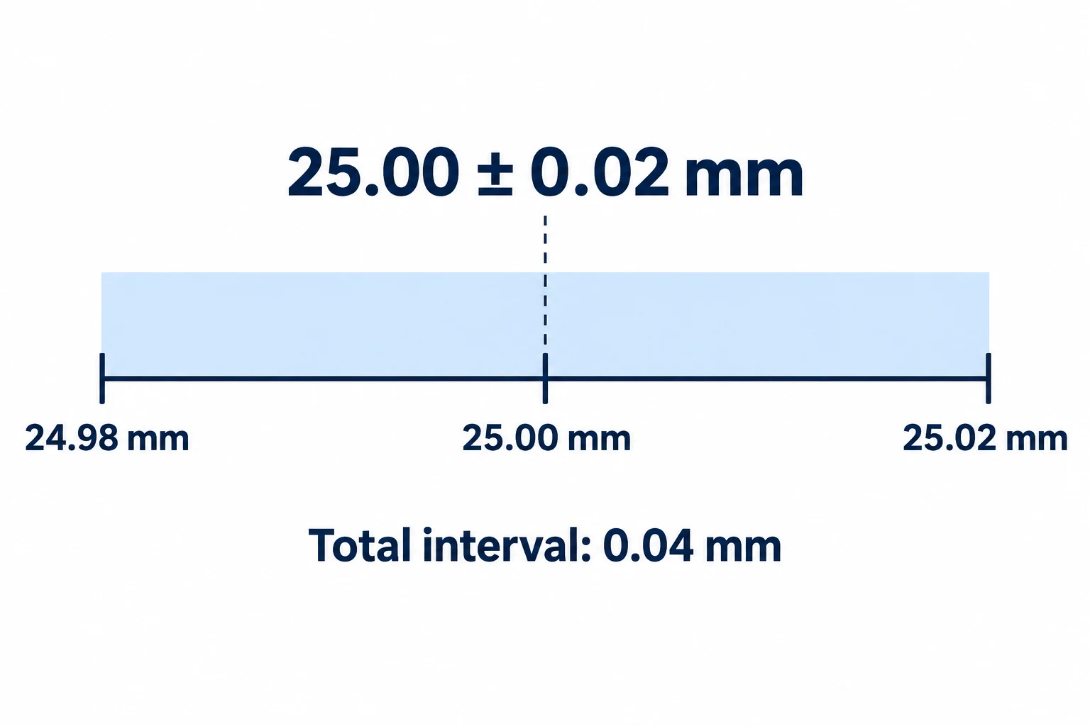
For a dimension of 25.00 ± 0.02 mm, the lower limit is 24.98 mm and the upper limit is 25.02 mm. The total tolerance interval is 0.04 mm. The ±0.02 value describes variation on each side of nominal, not the full interval.
| Illustrative size callout | Lower limit | Upper limit | Total interval |
|---|---|---|---|
| 25.00 ± 0.02 mm | 24.98 mm | 25.02 mm | 0.04 mm |
| 25.00 +0.03 / −0.00 mm | 25.00 mm | 25.03 mm | 0.03 mm |
| 24.98–25.02 mm | 24.98 mm | 25.02 mm | 0.04 mm |
The first and third entries express the same size limits. The second permits variation only above nominal. These are arithmetic examples, not recommended tolerances for a particular part.
A dimension without an adjacent ± value is not necessarily untoleranced. Check the title block, general notes, referenced specifications and any model-based requirements. A general-tolerance standard applies when the released definition invokes it within its stated scope; it is not automatically the default for every CNC part.
If two supplied files disagree, resolve the document priority or issue a consistent revision before production. Do not infer a tighter tolerance merely because a CAD system displays more decimal places. For inspection, record the actual requirement and its source, including the units and applicable drawing revision.
When a tight requirement adds work, first identify the function it protects. Keep the critical fit or geometric relationship, then review avoidable restrictions elsewhere with the design owner. For a specific drawing, VETCNC’s precision CNC machining service connects those requirements with the proposed route and inspection scope.
Calculate clearance from both mating parts
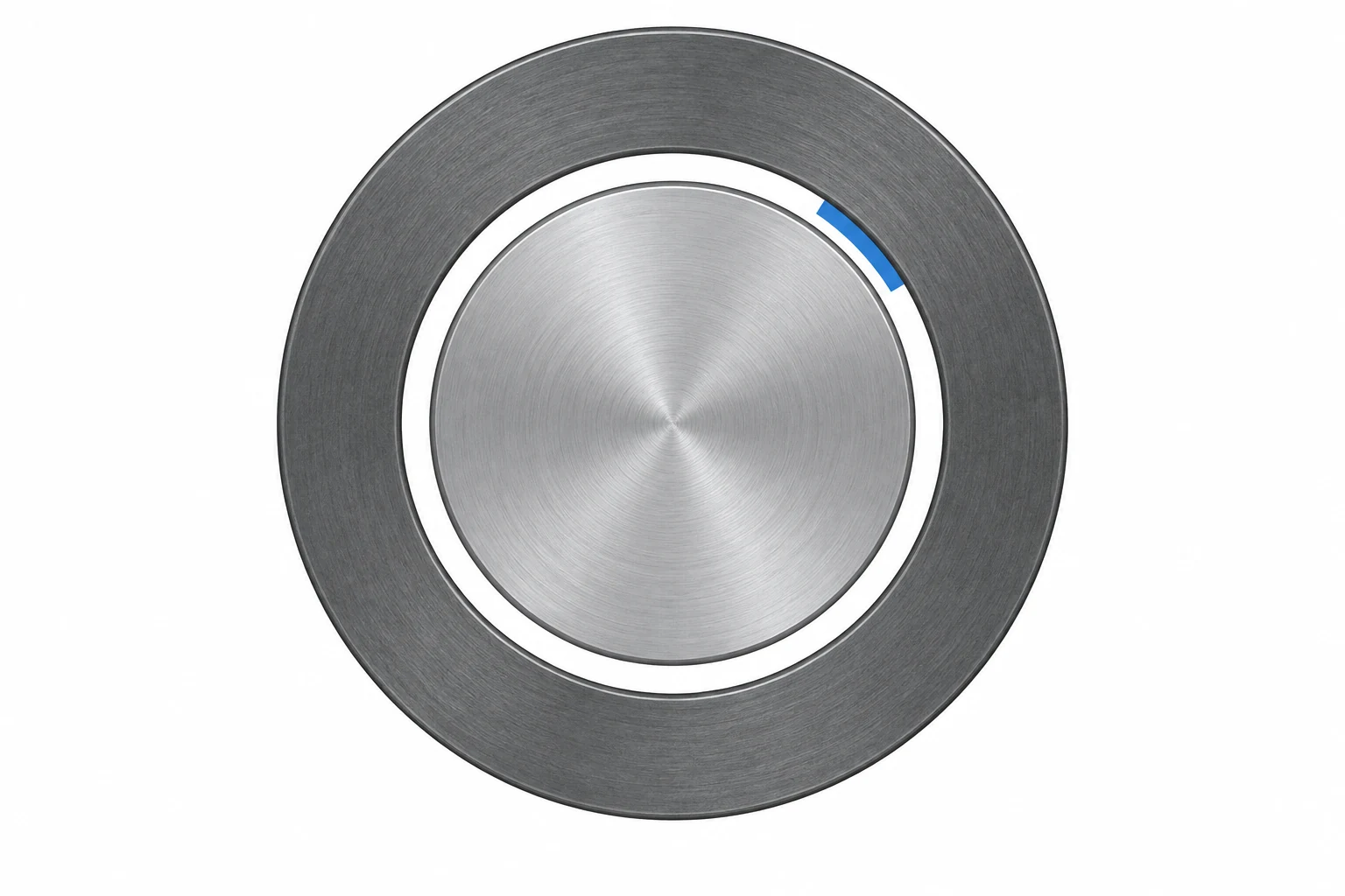
A fit belongs to a pair of features. Specifying a close bore tolerance while ignoring the shaft limits leaves the assembled clearance unresolved. For a clearance fit, the largest shaft does not exceed the smallest bore. For an interference fit, the smallest shaft is no smaller than the largest bore. A transition fit can produce clearance or interference depending on the actual sizes.
For a size-only example, assume a bore of 25.010–25.025 mm and a shaft of 24.990–25.000 mm, both in the same defined condition:
- Minimum diametral clearance: smallest bore − largest shaft = 25.010 − 25.000 = 0.010 mm.
- Maximum diametral clearance: largest bore − smallest shaft = 25.025 − 24.990 = 0.035 mm.
For ideal concentric cylinders, the corresponding radial gap is half the diametral clearance. That calculation does not establish actual assembly performance: form, orientation, surface condition, temperature and load can still change whether the interface works.
ISO 286 provides a standardized system for size tolerances and fits. A fit designation must be interpreted at the applicable nominal size using the specified standard; it is not a universal clearance number. The example above uses explicit dimensional limits rather than an ISO fit class. [2]
The same worst-case thinking applies to a simple axial stack. If a gap equals a housing length minus a spacer length, its minimum uses the smallest housing and largest spacer; its maximum uses the opposite combination. More dimensions require a complete signed chain. Statistical stack-up methods need justified distribution and process assumptions before replacing that worst-case check.
Use datums to describe the relationships that size cannot settle
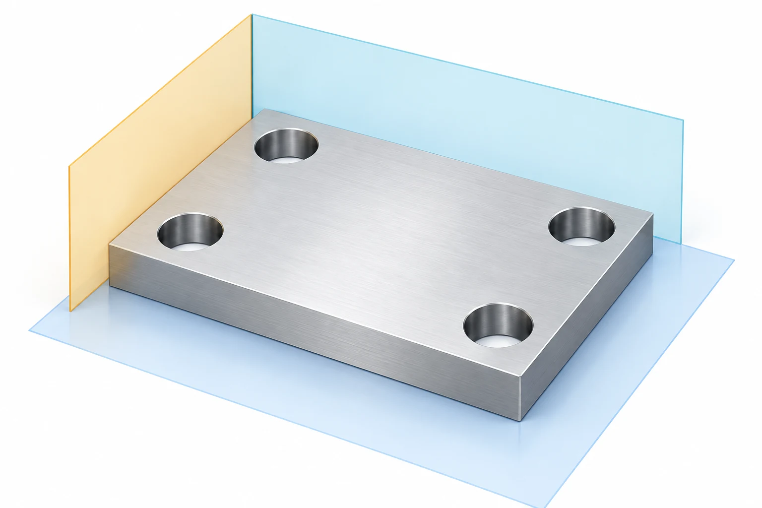
The flange’s hole diameters can all meet their limits while the pattern fails to align. The missing question is where the pattern belongs relative to the surfaces or axes that locate the assembly.
A datum is a theoretically exact reference established from a specified datum feature. For a plate-like part, the reference system might relate a seating face and two side features. A round assembly may instead rely on a face and a cylindrical feature that establishes an axis. Select those references from the functional relationship, then define them using the drawing’s specified conventions. [8]
Keep the control tied to the problem. Flatness addresses the form of a surface; parallelism relates its orientation to a datum. Position can control a hole pattern’s location and orientation relative to specified references. A flatness control alone does not say that the face is parallel to the opposite side. Mitutoyo’s form-measurement guide illustrates these distinct geometric questions. [3]
The inspection setup must reproduce the required reference system. Simply resting a part on whichever face is convenient can answer a different question. Clamping a flexible plate flat can also conceal its released shape; define any restrained condition when that is how the requirement is intended to apply.
Keep the material and finished condition in the tolerance plan
A dimension needs a physical condition. State the material grade and heat-treatment condition, which features are measured after coating, and whether the part is free or held in a defined restraint. A pre-coating diameter and a finished diameter are different stages of the same feature.
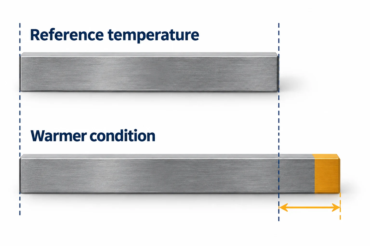
Temperature can be significant even for a simple length. NIST identifies 20 °C as the standard reference temperature for dimensional measurements unless another reference is specified. Measuring elsewhere may require a thermal correction and an uncertainty allowance appropriate to the material and task. [4]
Consider a 100 mm length at 20 °C. Assume a constant expansion coefficient of 11.5 × 10⁻⁶/°C, representative of the steel gage-block example discussed by NIST. At 25 °C:
ΔL = α × L × ΔT = 11.5 × 10⁻⁶/°C × 100 mm × 5 °C = 0.00575 mm = 5.75 µm.
This estimates the length change under the stated assumptions. The coefficient is not a value for every steel or alloy. A dimensional comparison also depends on the measuring system’s temperature behavior, gradients and the uncertainty of any correction.
Heat treatment, residual stress release and moisture-sensitive polymers introduce other condition-dependent changes. The materials and design guide explains why exact grades, conditioning and final finishing belong in the same review as the fit. Plan the operations so the specified condition exists when the critical features are finally checked.
Choose a method for the characteristic, not the display resolution
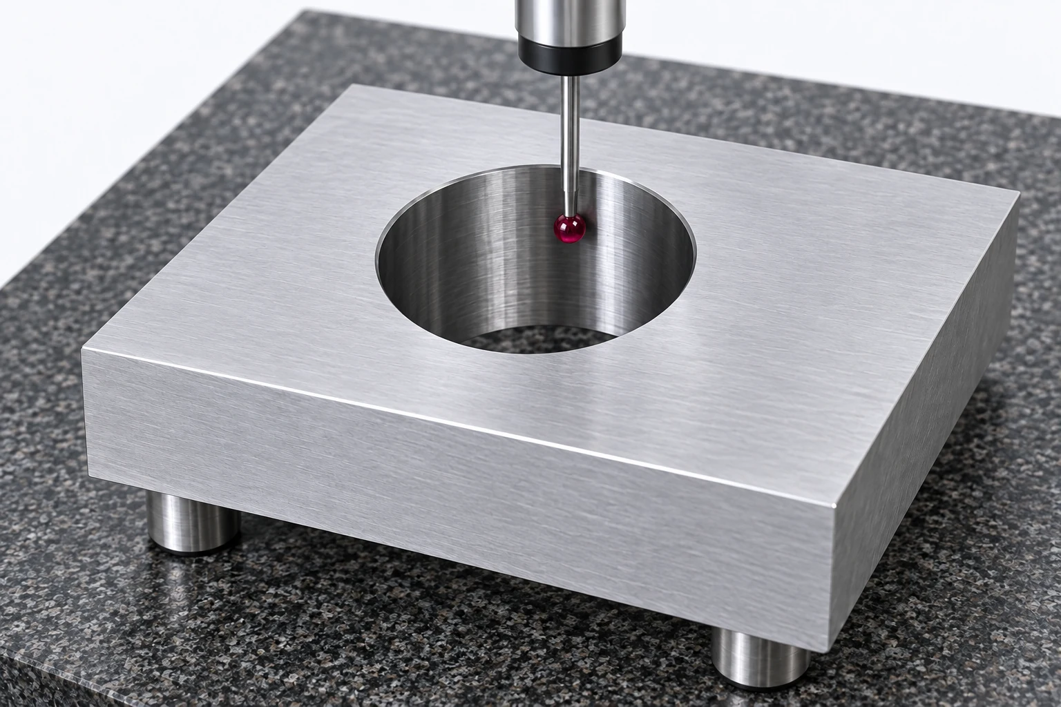
The measuring task determines the method. A coordinate measuring machine (CMM) can evaluate many dimensional and geometric relationships, but it still needs suitable access, probing, sampling, alignment and uncertainty for the characteristic. Owning a CMM does not make every measurement equally reliable. [8]
| Characteristic | Possible method | What the plan must address |
|---|---|---|
| Outside diameter | Outside micrometer or comparator | Contact, measuring force and positions checked |
| Bore size | Bore gage, internal micrometer or suitable CMM method | Access, depth, alignment and setting reference |
| Hole-pattern position | CMM or suitable dedicated gaging | Datum setup and complete geometric requirement |
| Surface flatness | Suitable form-measurement or CMM method | Surface coverage, support and evaluation method |
| Surface roughness | Suitable texture-measurement instrument | Specified parameter and evaluation conditions |
These are method families, not automatic approvals for a tolerance. A few diameter readings do not necessarily characterize the entire bore’s form. Likewise, a roughness measurement cannot substitute for a flatness evaluation.
Resolution is the smallest indicated increment; measurement uncertainty describes uncertainty associated with the result. Calibration, repeatability, alignment, contact and environment can contribute. A 0.001 mm display increment therefore does not establish 0.001 mm uncertainty. NIST’s uncertainty guidance considers the measurement process and its significant contributors, not only the instrument display. [5]
Similarly, machine positioning and repeatability specifications describe the machine under stated test conditions. They do not directly specify the tolerance of a machined feature. The article on interpreting machine specifications separates those claims from finished-part results.
Agree how results become an acceptance decision
A reported number and a pass/fail decision are different outputs. The decision rule defines how measurement uncertainty is handled when deciding conformity. Mitutoyo’s Decision Rules, TAR, and TUR explains why simple acceptance, uncertainty and measurement-quality requirements need to be considered together. No single resolution ratio or guard band should be assumed for every order. [6]
For a borderline result, use the applicable customer or specification rule and the qualified measurement method. Do not round the reading differently until it passes, or quietly change the rule after seeing the result.
An inspection record should identify the part and revision, characteristic, requirement, actual result and units, method or program, and the applicable acceptance basis. For critical features, also define the condition, relevant datum setup, inspection coverage and handling of discrepancies. The tolerances and inspection planning guide provides reusable worksheets for these decisions.
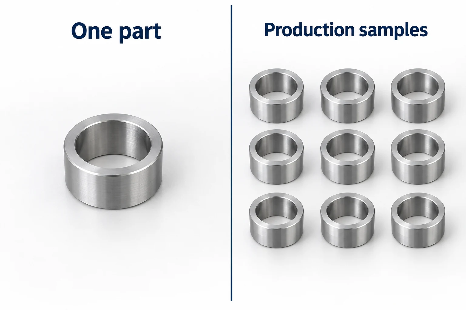
A first-part report supports conclusions about the characteristics and parts actually checked. It does not establish long-term process capability. Capability analysis compares process variation with specification limits and needs suitable data from a stable process; it cannot be inferred from one good sample. Inspection coverage, sampling and any required capability study therefore need separate definitions. [7]
CNC machining tolerance FAQ
What is a standard CNC machining tolerance?
There is no single default for every CNC part. Use the individual callouts, applicable general notes and referenced specifications in the released part definition. A supplier’s typical capability is not automatically the acceptance requirement.
Is ±0.02 mm a total tolerance of 0.02 mm?
No. It permits 0.02 mm on each side of nominal, giving a total interval of 0.04 mm. At 25.00 mm nominal, the size limits are 24.98 and 25.02 mm.
Can a part meet its size tolerances and still fail to fit?
Yes. Mating-part limits, feature location, orientation, form, finish and physical condition can affect the assembly. Diameter readings alone do not answer all of those questions.
Does a CMM report prove that the whole part is acceptable?
Only the reported, properly evaluated characteristics are covered by that report. Confirm the revision, datum setup, method, measurement condition, coverage and decision rule. Material or finish requirements may need different evidence.
Should dimensions be checked before or after coating?
Use the stage specified by the drawing or order. If the requirement defines the finished interface, verification must account for the final treatment and any masking or subsequent machining. Intermediate checks can still help control the process.
Does one approved sample prove repeat production will stay in tolerance?
No. It shows the outcome of the checks performed on that sample. Evidence about repeat production needs an appropriate inspection plan and, when required, process data and a valid capability evaluation.
Technical sources
- ASME. Y14.5 — Dimensioning and Tolerancing. Public scope of the GD&T standard; apply the edition specified by the drawing.
- ISO. ISO 286-1:2010 — ISO code system for tolerances on linear sizes: Basis of tolerances, deviations and fits. Scope of the standardized size-and-fit system.
- Mitutoyo. Quick Guide to Precision Measuring Instruments, form-measurement section, J-53. Distinct geometric characteristics and measurement setup.
- NIST. Engineering Metrology Toolbox: Frequently Asked Questions. Reference temperature, thermal correction and coefficient uncertainty.
- NIST. Essentials of Expressing Measurement Uncertainty: Basic Definitions. Significant contributors to a measurement result.
- Mitutoyo. Decision Rules, TAR, and TUR, EDU-15005A. Measurement quality and conformity decisions.
- NIST/SEMATECH. Engineering Statistics Handbook, 6.1.6: What Is Process Capability? Stable-process data and comparison with specification limits.
- KEYENCE. What Are Datums? and Measuring Machines, GD&T Fundamentals. Datum features, reference systems and coordinate measurement.



