On this page
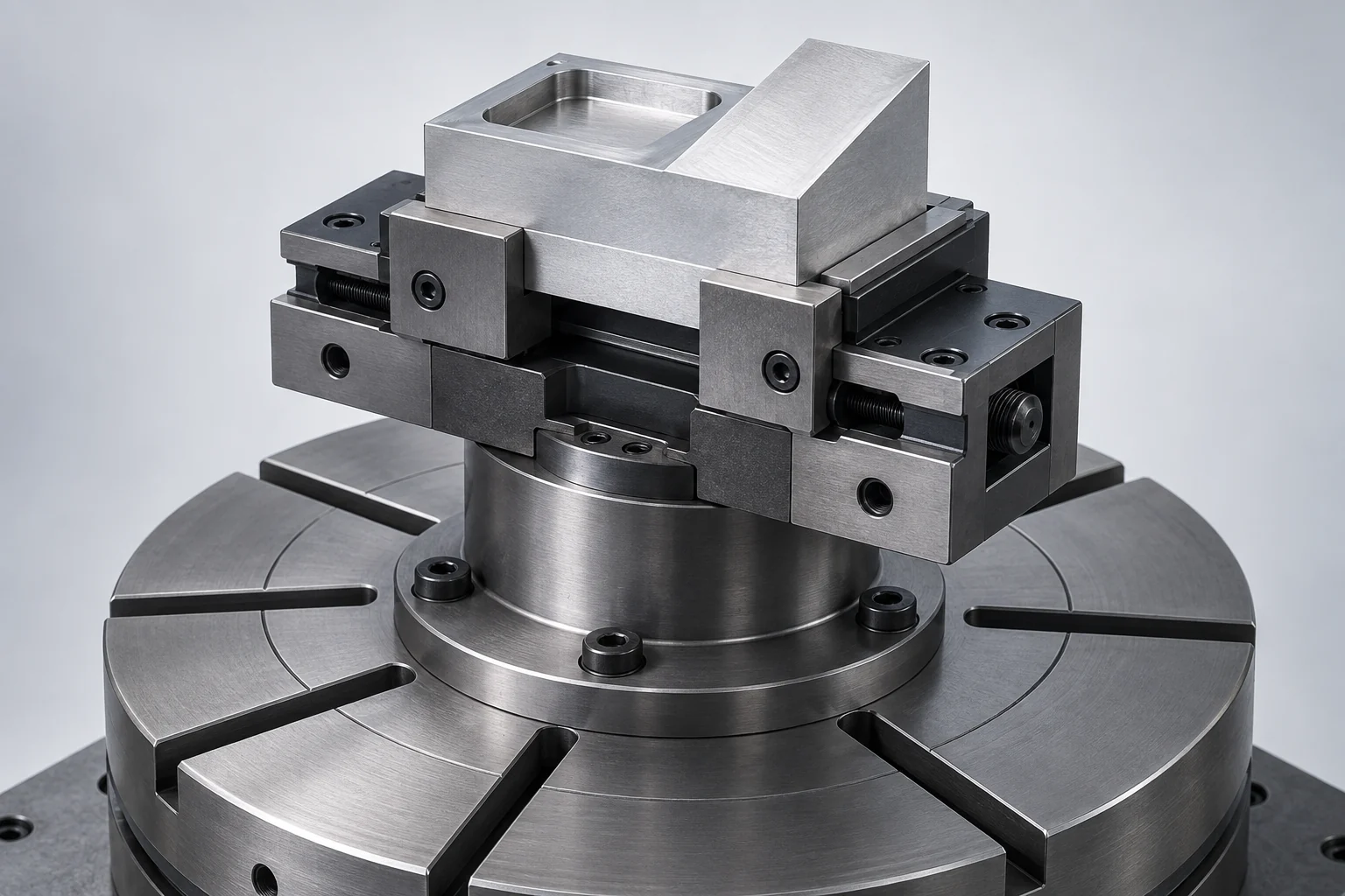
5-axis workholding locates and secures a part while leaving room for the cutter, holder and machine to reach the required features. A compact vise can expose more of a billet, but access is only half the job. The grip must also resist the changing cutting loads, support the remaining material and preserve a reference for any later setup.
These requirements apply to both 3+2 and simultaneous five-axis machining. Indexed cutting still needs a clear route between orientations. Continuous rotary motion adds more positions to check; neither mode exposes the surface that is physically inside the jaws.
Choose the grip around the surfaces that can be held
Start with a simple distinction: which surfaces belong to the finished component, and which material can be used for holding and removed later? A rough billet may tolerate serrated jaw impressions. A finished sealing land or visible anodized face presents a different contact problem.
The following are starting arrangements, not interchangeable fixture specifications. The blank shape, material, cutting loads and required access determine which version is suitable.
| Holding arrangement | Useful starting situation | What the process must resolve |
|---|---|---|
| Compact vise with gripping jaws | Raw stock with an accessible lower gripping band | Jaw engagement, stock preparation and removal of marked material |
| Dovetail fixture | Stock with a dedicated gripping feature below the part | Prepared dovetail geometry, load limits and later removal |
| Machined soft jaws | A second operation on a partly finished profile | Supported contact areas, seating and protection of finished surfaces |
| Dedicated fixture | Irregular geometry or accessible mounting features | Location, clamp access and clearance throughout the operation |
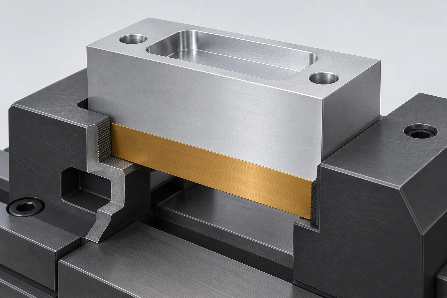
A shallow grip works as part of a particular system. For example, LANG Technik distinguishes its pre-stamped, form-fitting grip from ordinary friction clamping. Its published grip depth applies to that arrangement, not to every vise holding an arbitrary blank. Likewise, a dovetail needs the geometry specified for the chosen fixture. [1] [2]
A zero-point interface has another job: it relocates a compatible fixture or pallet on its base. It does not replace the jaws or clamps that secure the workpiece, and its repeatability is only one contributor to the finished part result. [3]
Check the holder and the path between cuts
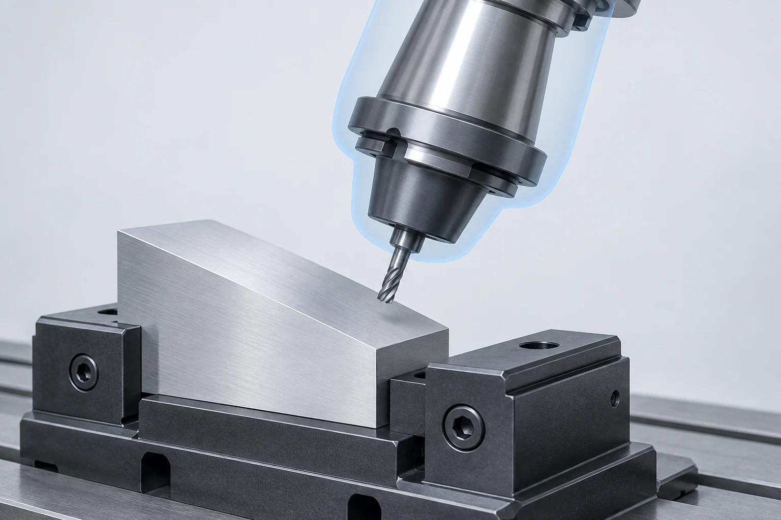
Imagine drilling an inclined hole near a block’s lower edge. The drill tip may line up with the hole while the wider holder meets the vise jaw. A longer tool could change that clearance, but also changes the tool assembly and its stiffness. Rotating the part farther may expose the hole while moving another corner toward the table.
A useful clearance review includes several different objects:
- Cutter and noncutting shank: verify that only the intended cutting region engages the stock.
- Holder and spindle: include the larger diameters behind the cutter.
- Stock and fixture: represent the actual blank, jaws, clamps, fasteners and riser.
- Machine motion: check rotary positions, linear travel and the space swept during reorientation.
Check entry, exit and linking moves as well as the cutting pass. Two clear cutting positions do not prove that the path between them is clear. The current stock shape matters too: material that disappears after roughing is still present before that operation.
Autodesk’s Simulation for manufacturing documentation distinguishes tool-and-stock simulation from simulation using the machine model, kinematics and postprocessor. Model the relevant fixture components and run the applicable collision and overtravel checks; a visually smooth animation alone is not the verification result. The model must correspond to the setup being used. [4]
Raise the part only as far as the setup needs
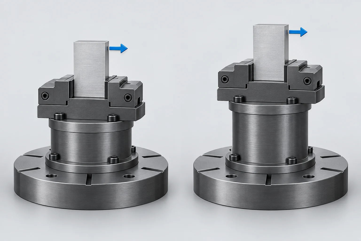
A riser can move the vise away from the table and open an approach to the part’s sides. Jergens describes this access benefit in its five-axis workholding guidance. The complete stack must still fit the machine and support the cut. [3]
Height affects more than access. For a horizontal force acting above a selected mounting plane, the moment about that plane is M = F × h, where h is the perpendicular distance to the force’s line of action. Consider a simplified comparison with the same assumed 200 N force:
| Force | Height above mounting plane | Moment at that plane |
|---|---|---|
| 200 N | 50 mm = 0.050 m | 10 N·m |
| 200 N | 100 mm = 0.100 m | 20 N·m |
The doubled height doubles this moment. It does not establish fixture deflection, a safe clamping force or a maximum usable riser height; those require the actual structure, interfaces and load directions. The calculation isolates one consequence of changing the distance between the cut and the mounting plane. [5]
The stack also consumes space and adds mass. On a tilting table, assess the combined fixture and workpiece against the relevant payload, center-of-gravity and moment limits. Check the tilted envelope, not only the upright height. Our guide to reading machine travel and clearance specifications explains why travel alone does not define the available part space.
Keep clamping loads away from unsupported walls
The fixture holds different structures as machining progresses. A solid blank may become a thin pocketed housing while it remains in the same jaws. Contact that was acceptable during roughing can become a source of movement when the surrounding material is gone.
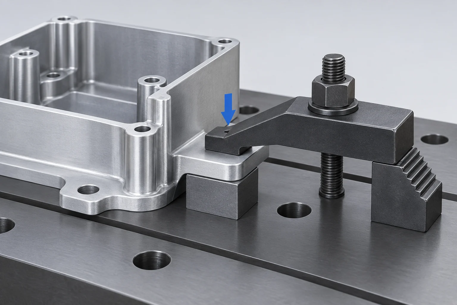
Direct clamping loads into supported, sufficiently stiff regions. A clamp over a solid flange with support immediately underneath creates a different load path from a clamp bending an unsupported wall. Carr Lane’s Locating & Clamping Principles explains this relationship between clamp position, support and distortion. Tightening harder is not a general remedy for a flexible part. [6]
Surface requirements also belong in the holding plan. Mark the faces where jaw impressions can remain, the areas that will be machined away, and the surfaces that must be protected. “No marks” on every surface can rule out an otherwise practical grip and require different contact geometry or another operation.
Soft jaws describe machinable jaw inserts, not a guarantee of mark-free contact. Their fit, contact area, cleanliness and applied load still matter. A trapped chip can affect both the seating and the contacted surface. Separate appearance acceptance from dimensional acceptance: a part can look undamaged yet move when unclamped. [1] [6]
The machining materials and design guide connects these questions to thin walls and the specified inspection condition. For flexible parts, make clear whether the drawing’s requirement applies free of the fixture or under a defined assembly restraint.
Plan the second setup before removing the gripping stock
Consider a housing with a top pocket, side holes and a finished bottom mounting face. An initial setup may hold extra material below that mounting face, leaving the top and sides accessible. After those features are machined, the remaining grip stock still has to come off.
The second setup needs a place to sit, a way to resist the next cut and usable references to the features already made. Machined soft jaws may support the external profile, or a dedicated fixture may locate from suitable finished features. Select those contacts while planning the first operation, rather than discovering after machining that every convenient holding surface is delicate or cosmetic.
For this housing, follow the relationships that matter:
- Identify the bottom face and side-hole relationships that the finished drawing controls.
- Choose accessible locating features that carry those relationships into the second setup.
- Leave enough usable material and support for removing the grip stock without losing the part’s location.
- Check the finished relationships after release and any specified finishing operations.
A coordinate offset can describe the part’s position, but it cannot compensate for an unknown seating error or a part that moves under load. Similarly, a repeatable pallet interface does not prove that the component is seated correctly in its jaws. Clean contacts and an appropriate reference check remain part of each setup. [6]
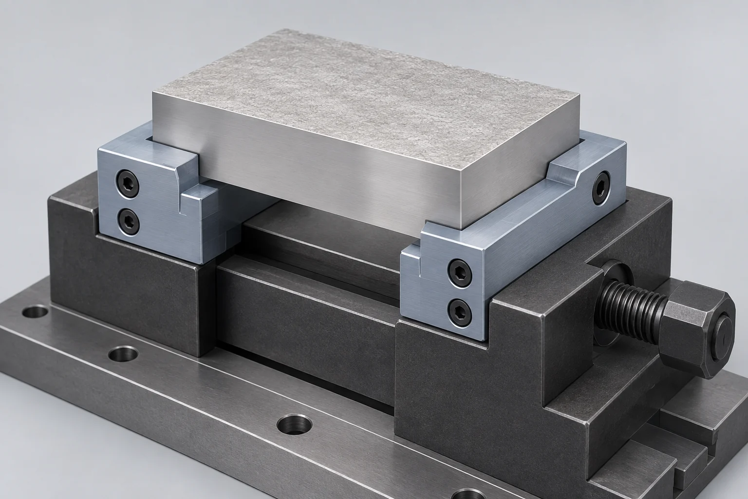
The useful outcome is a complete route: the intended faces can be reached, the part remains supported as stock disappears, and the final holding operation preserves the required feature relationships. For a part-specific manufacturing review, VETCNC’s five-axis CNC machining service covers tool access, workholding allowance and inspection requirements.
5-axis workholding FAQ
Does a five-axis vise let me finish all six sides in one setup?
Not by itself. Jaws or gripping stock usually obstruct part of the component. Five-axis motion can expose additional directions, but removing the remaining contact area requires a planned holding or transfer method.
Is a dovetail necessary for five-axis machining?
No. Dovetails are one holding option. Gripping jaws, machined soft jaws and dedicated fixtures can suit other parts. The choice depends on accessible contact areas, stock preparation, loads and the later finishing sequence.
How much material should I leave for the jaws?
Use the requirements of the selected holding system and the actual machining plan. There is no universal gripping depth for every material, jaw and cutting load. Include the material needed for preparation and for completing the second operation.
Does a taller riser improve the setup?
It can improve access, but also changes the height, load moment and swept envelope. Choose the height needed for clearance while checking the fixture structure and the machine’s applicable load and travel limits.
Can soft jaws prevent all clamp marks?
No. Well-fitted jaws can distribute contact over suitable areas, but load, chips and surface condition still affect the result. Identify protected faces and define acceptable contact marks before choosing the grip.
Technical sources
- LANG Technik. Frequently asked questions about workholding systems. Jaw selection and pre-stamped raw-stock holding.
- Jergens. Workholding Solutions Master Catalog. Five-axis dovetail vises and prepared gripping features.
- Jergens. 5-Axis Knowledge Center: Overview. Risers, fixture interfaces and modular workholding.
- Autodesk Fusion Help. Simulation for manufacturing. Machine models, verification, collisions and overtravel.
- OpenStax, Rice University. University Physics Volume 1, Section 10.6: Torque. Force and perpendicular moment arm.
- Carr Lane Manufacturing. Locating & Clamping Principles. Supports, load direction, chip clearance and part location.



