On this page
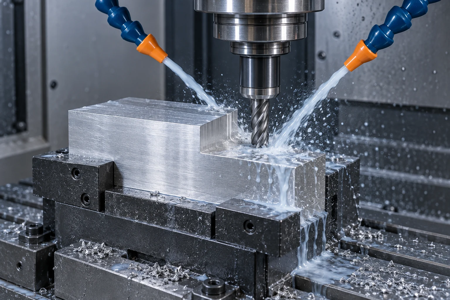
CNC machine coolant helps manage heat, reduce friction and move chips away from the cut. Those are separate jobs: a wet workpiece does not prove that fluid reaches the cutting edge, and a strong jet does not guarantee that chips can escape a deep hole. Choose the fluid and its delivery method around the material, tool and feature being machined.
Cooling, lubrication and chip removal do different work
- Cooling carries heat away from the cutting region and surrounding surfaces.
- Lubrication reduces friction at the contacts between the tool, chip and workpiece.
- Chip removal helps move separated material out of the cut so it does not accumulate or get cut again.
The balance changes with the operation. An accessible face and the bottom of a narrow hole present different delivery paths. Our CNC milling process guide explains how cutter engagement and toolpaths change the cutting task.
Fluid chemistry is another choice. OSHA groups metalworking fluids into straight oils, soluble oils, semisynthetics and synthetics. Straight oils are used without water dilution; the other three categories are generally supplied for mixing with water. The product’s application instructions govern its use. A fluid’s color does not establish its suitability or concentration. [1]
Match the delivery path to the feature
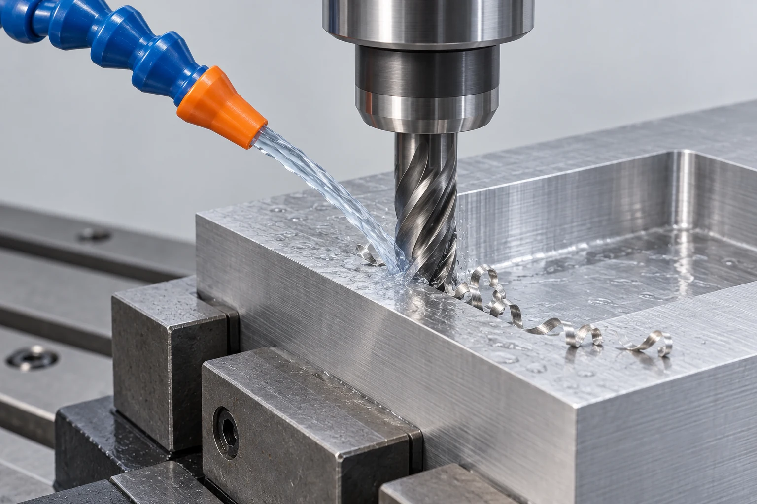
“Flood coolant” names a delivery approach, not a fluid formulation. Likewise, through-tool coolant describes a route through passages in compatible tooling. The same fluid family may be delivered in different ways.
| Approach | Useful role | What still needs checking |
|---|---|---|
| External flood | Supplies an accessible cutting area | Nozzle aim, shielding by the part and chip escape |
| Through-tool coolant | Delivers fluid close to a recessed cutting edge | Compatible spindle/holder/tool path, pressure and flow |
| Minimum quantity lubrication (MQL) | Delivers a small amount of lubricant with air | Purpose-suited equipment, tool and application |
| Air blast | Air can assist chip removal where liquid is not selected | Tool/material suitability and effective chip or dust containment |
MQL adds lubricant; plain air does not. Air is also a poor substitute for liquid heat removal in applications that need it. Sandvik Coromant distinguishes these media and their delivery requirements in its turning guidance. [2]
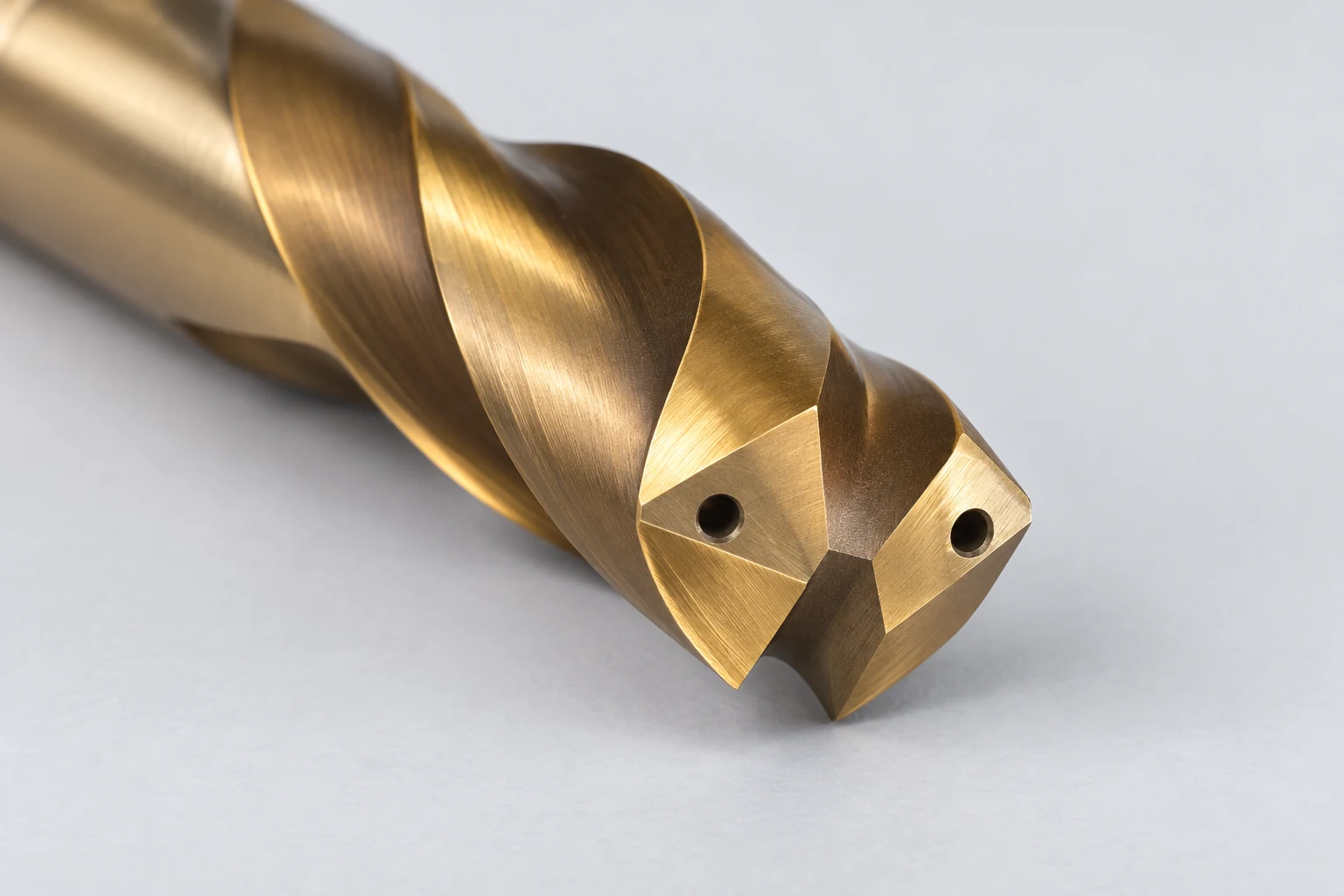
Through-spindle coolant can carry fluid through a compatible holder and drill to outlets near the tip. Chips still need a return path along the flutes. A deeper hole increases the importance of that complete path; fluid arriving at the tool is only part of the problem.
Pressure and flow are different quantities. Pressure is expressed in units such as bar or psi; flow is volume per time, such as liters per minute. Haas notes that tool-passage size changes the pressure and flow delivered by its TSC system. Compare the pump and tooling together, rather than treating the highest pressure on a specification sheet as the best setting. [3]
More coolant is not a universal improvement
Milling repeatedly moves a cutting edge into and out of the material. Cooling a hot edge between engagements can intensify thermal cycling and contribute to cracking. For some carbide milling applications, dry cutting is appropriate. Other applications benefit from liquid for lubrication, surface quality or chip control.
Sandvik’s wet-or-dry milling guidance describes both effects. Select the tool grade, material and cutting conditions together; if the chosen process runs wet, maintain the supply required by that application. A rule such as “all aluminum wet” or “all steel dry” skips those conditions. [4]
In turning, a directed jet can help control the chip, but the nozzle arrangement and cutting conditions determine the result. For grooving and parting operations, the narrow space around the tool makes chip evacuation particularly relevant. Sandvik’s coolant guidance separates pressure, outlet area and flow requirements; its application examples are not universal settings. [5]
Follow the chip path, then check the delivered part
When finish or tool life deteriorates, examine what is happening before changing the coolant specification:
- Chips collect in a pocket: check the exit path, nozzle access and toolpath before assuming more pressure will clear them.
- The cut receives an intermittent stream: check delivery consistency and obstructions within the equipment’s prescribed maintenance procedure.
- The tool edge is damaged: review the wear pattern, engagement and cutting data as well as the wet/dry choice. Appearance alone does not identify the cause.
Fluid condition is a separate control. Use the supplier’s concentration and water-quality guidance, and maintain filtration and contamination control. Avoid prescribing one mixture percentage for every product. OSHA’s advisory manual discusses fluid management and mist-control measures; coolant selection also needs the product’s current safety information. [1]
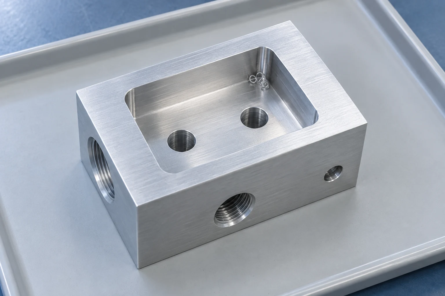
For a manifold, sealing component or part that will be bonded or coated, define the required delivered condition: passages to clean, residue restrictions and how cleanliness will be accepted. Include those requirements with the material and drawing when reviewing CNC milling. Specifying the result is usually more useful than asking for a particular pump pressure.
FAQ
Is CNC coolant just water?
No. Some cutting fluids are oils used directly; others are formulated concentrates mixed with water. Plain water does not provide the same lubrication, corrosion protection or fluid stability as a suitable working mixture.
Does through-spindle coolant eliminate peck drilling?
It can enable a continuous drilling cycle with appropriate tooling and conditions, but it does not eliminate pecking for every drill, material or depth. Follow the selected tool’s application limits.
Does a shiny machined surface prove the coolant worked correctly?
No. Appearance alone cannot establish dimensions, surface texture, tool condition or cleanliness. Check the characteristics required by the drawing and the process.
Technical sources
- OSHA, Metalworking Fluids: Safety and Health Best Practices Manual, fluid categories and management. Advisory guidance, not a new regulation.
- Sandvik Coromant, How to Apply Coolant and Cutting Fluid in Turning, coolant media and outlets.
- Haas Automation, Through-Spindle Coolant (TSC), passage size, pressure, flow and tool-dependent drilling examples.
- Sandvik Coromant, Dry Milling or with Cutting Fluid, thermal cycling and application exceptions.
- Sandvik Coromant, Coolant Aspects — Machining with Coolant, pump requirements and chip evacuation.



