On this page
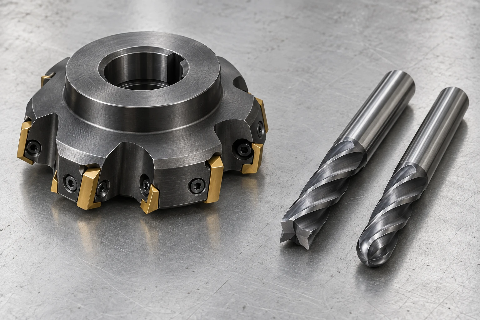
A face mill usually covers a broad surface, while an end mill reaches into slots, pockets and smaller features. A ball-nose cutter is a type of end mill, identified by its rounded tip. Those names describe different aspects of a tool; they are not three mutually exclusive machining processes.
For a part designer, the useful distinction is the shape the rotating cutter can leave behind. Its outside diameter controls one kind of internal corner. Its end profile controls another.
Face mills and end mills: tool names versus operations
A typical indexable face mill has a broad body carrying replaceable inserts. It suits accessible flat faces where the workpiece and setup can support its engagement. Insert geometry also matters: face mills with different entering angles do not all produce the same shoulder shape.
End mills have cutting edges around a relatively slender body and, depending on their design, at the end. They can machine walls, pockets and profiles. An end mill can also face a small area; the operation does not require a tool sold as a “face mill.” Our explanation of how CNC milling works puts these tools in the context of tool motion and workpiece setup.
Square, corner-radius and ball-nose end profiles
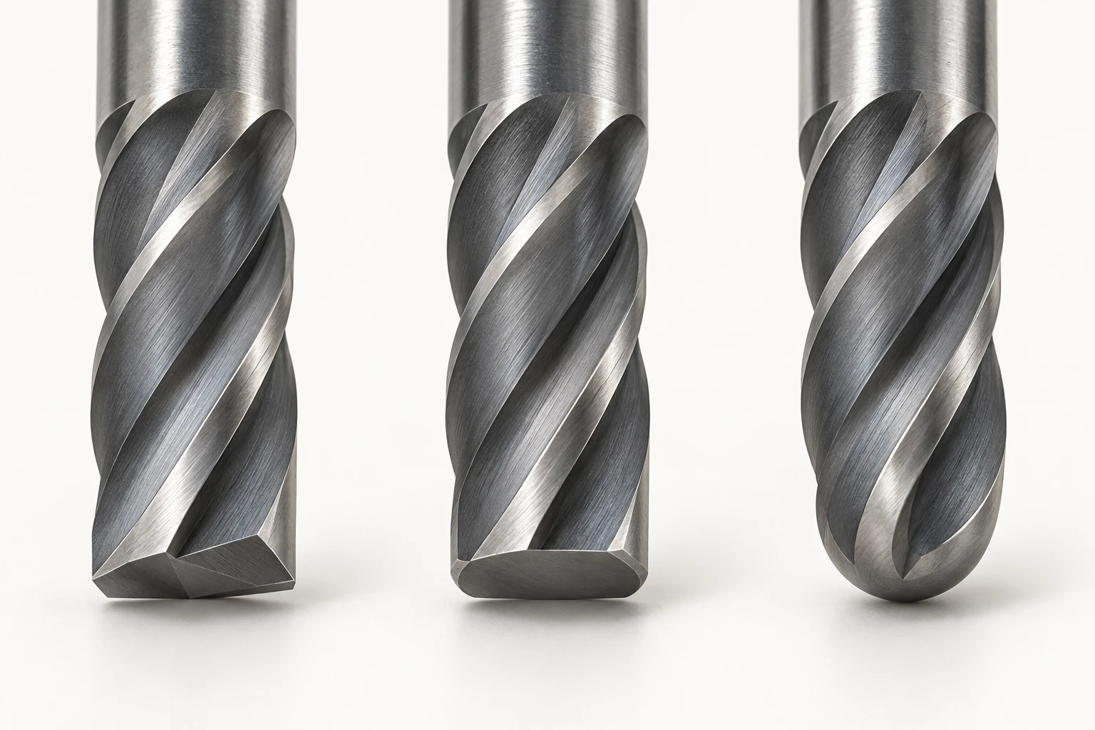
| End profile | Geometry at the tip | Feature implication |
|---|---|---|
| Square end | Flat end, nominally square outer corners | Flat floors and near-square wall-to-floor junctions |
| Corner radius, or bull nose | Flat central end with rounded outer corners | Flat floors with a specified bottom blend |
| Ball nose | Hemispherical end | Contoured surfaces and curved transitions reached by the toolpath |
A “square” tool does not guarantee a mathematically sharp finished corner. Edge preparation, wear and cutting conditions affect the result. Likewise, “ball nose” does not mean every radius on the part must equal the ball radius. The toolpath generates the surface, subject to access and interference limits.
A pocket has two different corner radii
Look down into a rectangular pocket: adjacent vertical walls meet at an internal corner. Now look at a section through one wall: the wall meets the floor at a separate transition. These radii lie in different planes.
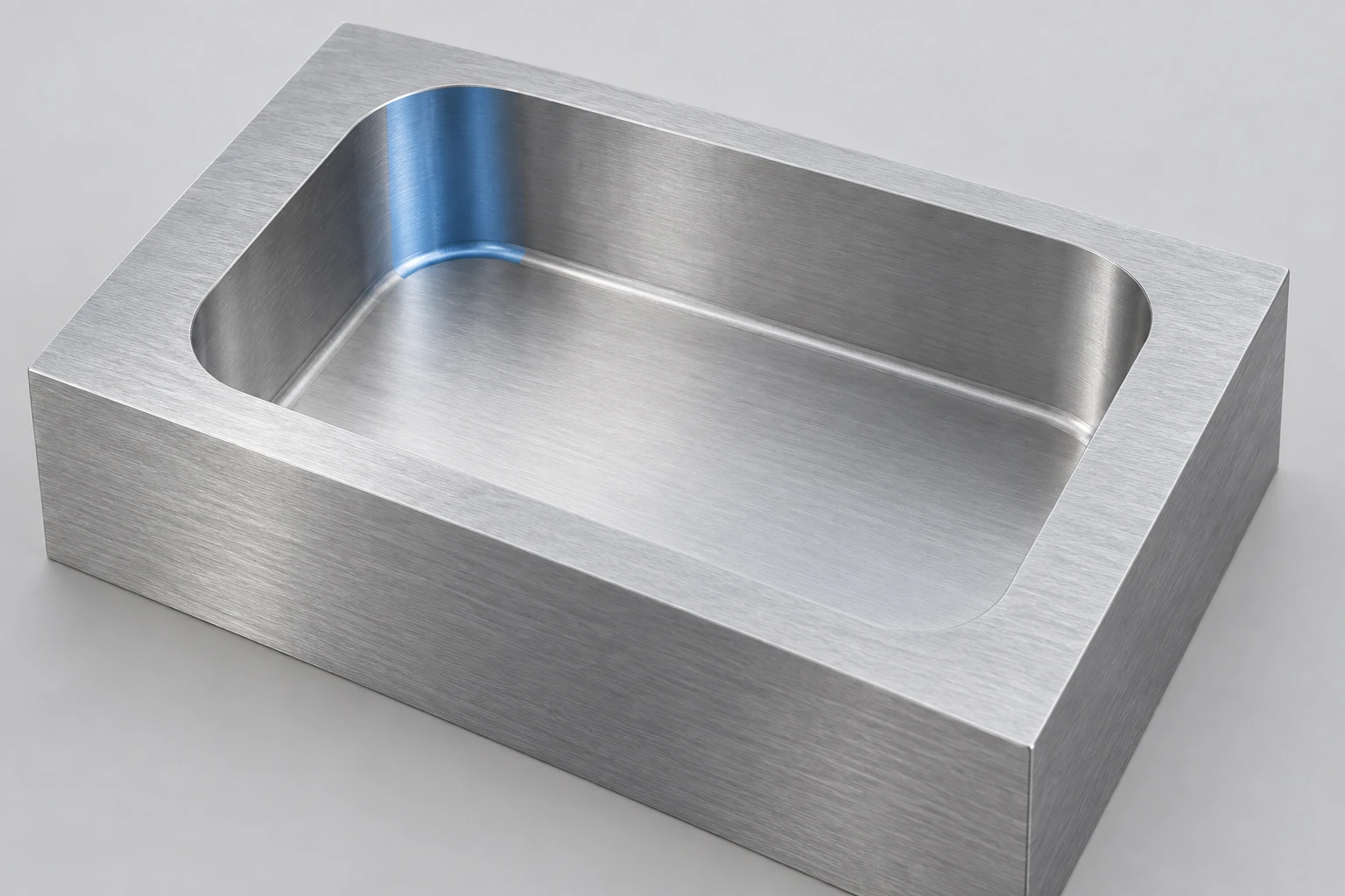
Consider an idealized, vertical 6 mm diameter corner-radius end mill with a 0.5 mm end-corner radius:
- Viewed from above: its rotating cylindrical envelope has a 3 mm radius. In conventional end milling, it cannot produce a smaller concave corner between the pocket walls.
- Viewed in section: its 0.5 mm end-corner profile can form a 0.5 mm wall-to-floor fillet when that profile is fully engaged.
- A 6 mm ball-nose tool is different: its hemispherical tip has a 3 mm radius, rather than a small 0.5 mm corner adjoining a flat end.
These are geometry relationships, not finished-part tolerances. A pocket corner exactly equal to the cutter radius also creates heavy engagement. A smaller cutter gives room to follow the required corner with a more controlled path; the actual choice depends on depth, material and stability.
Dimension the corner that matters to the mating part. A bottom blend that clears a mating chamfer does not establish the clearance at the pocket’s vertical corners. The materials and part-design guide connects these local features with the rest of the drawing.
Contact diameter and tool reach need separate checks
On a ball-nose tool, the effective cutting diameter depends on where the surface contacts the ball. At the exact center, rotational surface speed is zero. Contact farther from the center behaves differently even at the same spindle speed. Tool orientation can move contact away from the center where machine motion and part access permit; a nominal diameter alone does not establish the cutting conditions.
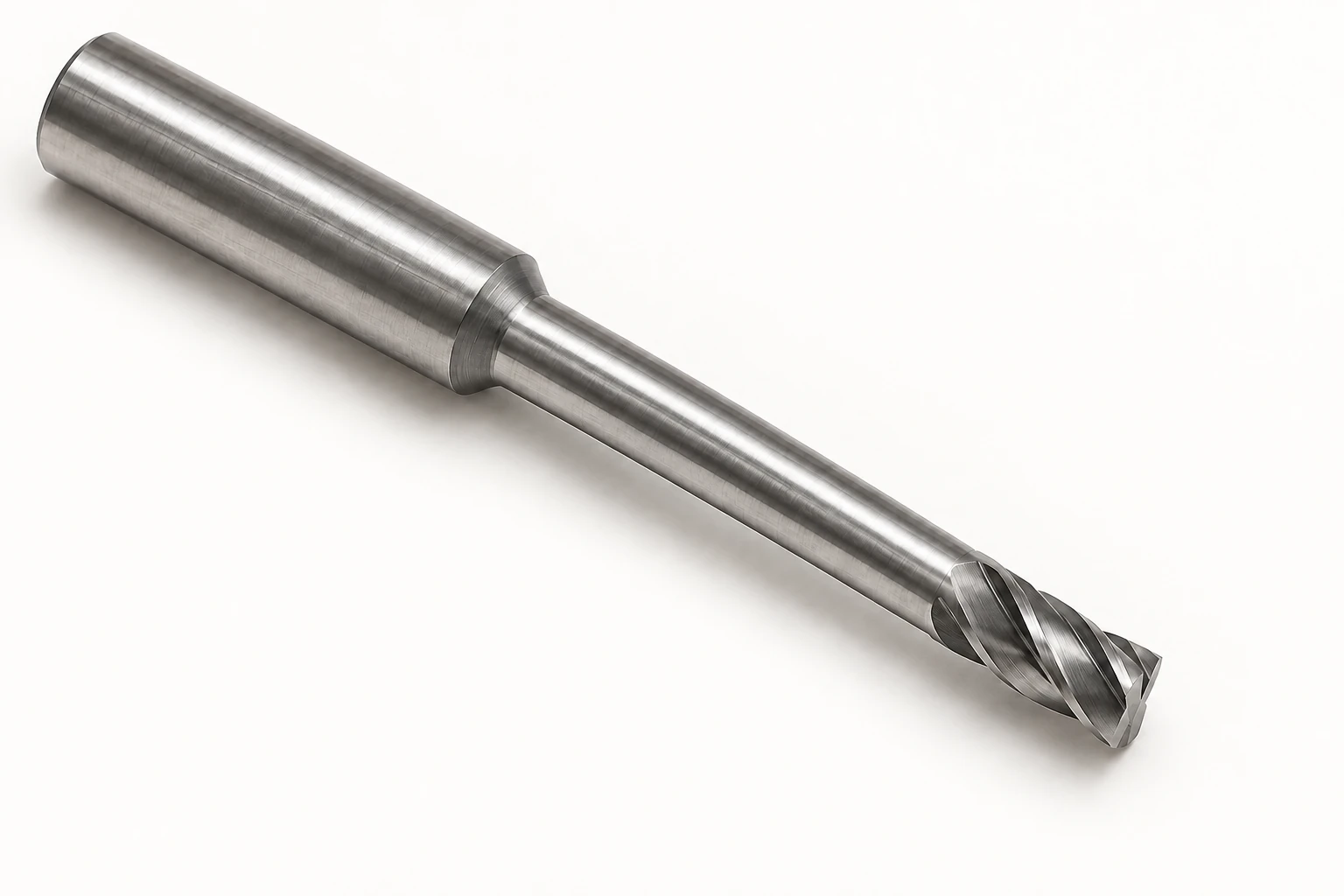
On a long-reach tool, distinguish the dimensions:
- Cutting length: the axial length of the cutting edges.
- Reach below the shank: the distance from the start of the relieved neck to the tool tip, including the cutting head.
- Overall length: the entire tool, including the portion held in the holder.
A tool can reach a deep feature without having flutes along its full exposed length. That does not mean its smooth neck may rub against a wall, or that the holder clears the part. The complete tool assembly and motion need checking.
Flute count, edge geometry and coating then refine the selection for the material and cut. More flutes do not automatically make a better tool: chip space and engagement matter too. For a CNC milling review, the meaningful inputs are the feature geometry, material, required surfaces and access direction. Tool dimensions follow those requirements.
Frequently asked questions
Can an end mill plunge straight down like a drill?
Only a tool designed for the intended axial entry should do so. Center-cutting geometry matters, but it does not replace the manufacturer’s limits for plunge depth, feed and chip evacuation. Other tools require a suitable ramp, an existing opening or a different entry method.
Can a face mill cut a 90-degree shoulder?
A cutter designed for shoulder milling can; many general face mills cannot leave that wall geometry. Check the entering angle, insert shape and permitted cutting depth rather than inferring the result from the name “face mill.”
Can a coating make the same end mill suitable for every metal?
No. The substrate, cutting-edge geometry, chip space and operating conditions also affect suitability. A coating that works well in one material may be a poor choice in another. Use the tool manufacturer’s recommendation for the specific material and application.
Technical sources
Tool terminology and selection: Harvey Performance, The Anatomy of an End Mill and 5 Questions to Ask Before Selecting an End Mill. Ball-contact considerations: Harvey Performance, Ball Nose Milling Strategy Guide. Tool entry: Harvey Performance, Most Common Methods of Tool Entry. Face-cutter geometry and corner engagement: Sandvik Coromant, Face milling and Milling inside corners. The 6 mm / 0.5 mm dimensions above are a geometric explanation, not a factory capability specification.



