Headed punch blanks
We machine the body, mounting head and shoulders of drawing-defined punch components. The working end is produced to its specified profile and delivered condition, rather than inferred from the outside diameter alone.
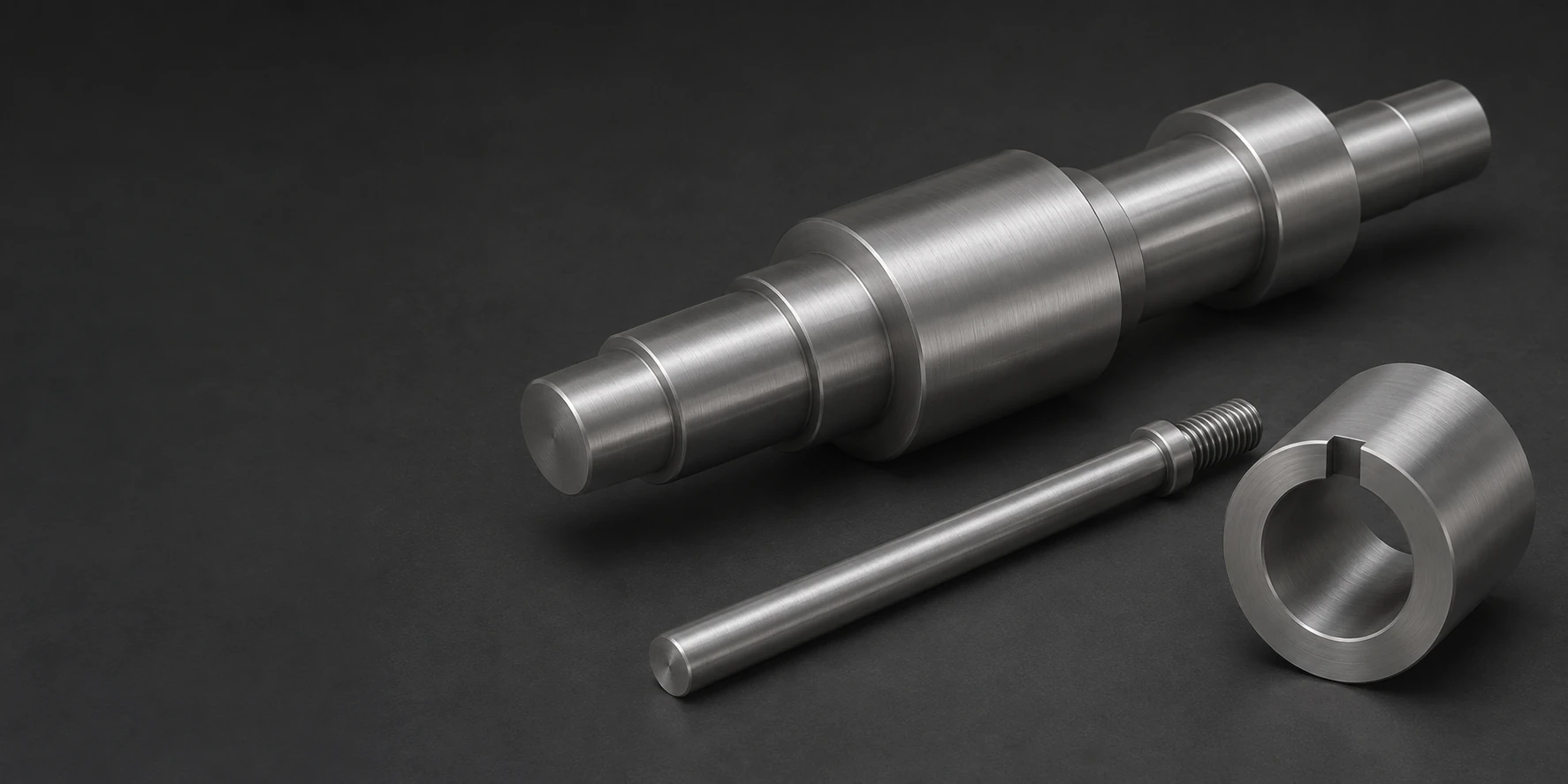
We machine the body, mounting head and shoulders of drawing-defined punch components. The working end is produced to its specified profile and delivered condition, rather than inferred from the outside diameter alone.
CNC turning forms the stepped pin in soft stock and leaves allowance on the guiding diameter and locating shoulder for final finishing after heat treatment. Check both working features in the delivered hardness condition.
A guide sleeve combines an internal working bore with an outside locating surface and an axial stop. The bore, mounting fit and face relationship are accepted as separate functional features.
A replaceable ring or bushing places a defined contact surface on a separate component. Its attachment fit must retain the component without obstructing the intended working clearance.
We machine seats, steps and fastening features in rectangular tooling inserts. The supported working face and surrounding section determine how the insert fits into its holder.
A mandrel-like component carries a working cylindrical profile together with its mounting features. The usable contact length, supporting shank and locating references belong to the same drawing definition.
Our SKH51 service covers drawing-defined tooling components with the soft-machining, treatment and final-feature scope identified in the quotation. We separate a machined blank from a hardened and finished working component.
An annealed blank allows the main shape, mounting features and machining access to be established before hardening. NACHI’s SKH9 reference, related to JIS SKH51, lists annealed hardness below 255 HB.[1]
Pre-hardened material can reduce the amount of later thermal processing when its available form and condition suit the component. It changes the machining task from bulk soft cutting to the operations feasible at the supplied hardness.[1]
The NACHI catalogue lists 58–66 HRC across SKH9’s hardened-and-tempered uses, not one mandatory hardness for every tool. A cutting edge, forming contact and guiding feature place different demands on wear resistance and toughness.[1]
NACHI lists SKH9 under conventional high-speed steel production and identifies powder-metallurgy grades separately. A requirement for powder material or a named producer must be carried into the stock definition rather than inferred from an HSS description.[1]

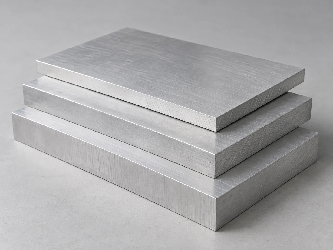
The SKH9 catalogue chemistry below is a producer’s nominal reference for its SKH51-related steel. It identifies the tungsten, molybdenum, chromium and vanadium alloy system, while heat treatment, hardness and working-surface geometry are specified for the part itself.[1]
NACHI producer-reference data retain their own named grade and condition; they are not measured VETCNC component results.
| Parameter | Reference value | Unit | Producer basis |
|---|---|---|---|
| Carbon | 0.88 | mass % | SKH9 nominal chemistry |
| Tungsten | 6.0 | mass % | SKH9 nominal chemistry |
| Molybdenum | 5.0 | mass % | SKH9 nominal chemistry |
| Chromium | 4.0 | mass % | SKH9 nominal chemistry |
| Vanadium | 2.0 | mass % | SKH9 nominal chemistry |
| Annealed hardness | <255 | HB | Catalogue condition |
| Hardened and tempered | 58–66 | HRC | Catalogue application range |
NACHI Material’s General Catalog S2001E-6. Nominal producer chemistry and separate condition ranges are references for material/route selection, not a universal finished-tool hardness or an acceptance certificate.

We machine the body, shoulders, holes and attachment details while the selected route permits access. Small working sections need enough remaining support to survive the operations that follow.
Slots, flats and shaped ends connect the working feature to its holder and motion. Their position follows the mounting datum rather than a separate reference chosen only for convenient cutting.
A hardened journal, bore or edge may require an appropriate grinding or other final operation. The route must preserve access and avoid treating the soft-machined size as the finished working surface.[1]
A working feature is accepted for geometry, surface condition and the stated material condition.
| Feature | Specified requirement | Accepted condition | Verification |
|---|---|---|---|
| Guiding bore or pin | Size and geometric control | After included final finishing | Bore/diameter geometry check |
| Mounting shoulder | Location and face relationship | Defined support/datums | Face/length measurement |
| Working tip or profile | Shape and permitted edge | Delivered working surface | Applicable profile check |
| Hardness location | Required scale and limit | Permitted test region | Specified hardness method |
We inspect the selected dimensions and relationships against the tool drawing. Overall length, body diameter and a hardness value cannot replace the separate limits on a working tip or bore.
A slender tip needs a transition into its supporting section. The remaining material and transition shape affect both machining access and how the working end is supported in the tool.
An open guide sleeve and a blind internal profile do not give the finishing tool the same access. The required final profile must be compatible with the operation planned after hardening.
A relief can provide clearance for final grinding and the mating corner. Its location must preserve the shoulder’s seating area and the supporting section behind it.[1]
A screw hole or mounting slot needs enough material around it without interrupting the intended contact surface. Separating attachment from the working area can also provide a suitable identification location.
A working end transfers load through the body into its holder. Contact profile, supporting section and retention determine how the component functions alongside the specified hardness.
A guide controls the relationship between moving parts through its actual contact length and clearance. The internal working surface is located and measured through its actual contact length and clearance.
A separate wear insert can preserve the holder while the contact component is replaced. Its mounting interfaces need to reproduce the accepted position without relying on the worn face of the removed part.
A mandrel or supported profile establishes contact along a defined region. The surrounding mechanism determines the load path and the available installation and removal access.

A guiding bore, forming face and cutting edge require different surface definitions. The location and direction of a controlled finish belong with the working feature’s geometry.
An edge radius or chamfer changes a working tip. It must follow the tool definition; ordinary burr removal cannot silently become a larger edge preparation.
A selected coating is a separate process with its own thickness and compatibility requirements. It must suit the base material condition and the finished contact rather than being assumed from the HSS grade.
Tips, narrow lands and finished bores need protection from contact damage. Marking and packing should leave those working features clear for installation.

The stock record identifies the ordered steel and any named producer or material route. Visual appearance cannot distinguish the required SKH51 material from another polished tooling steel.[1]
Hardness is checked using the required scale and an appropriate permitted location. A result taken on the body must be interpreted according to the specified acceptance plan, not presumed to describe every small feature.
We inspect the selected bore, tip, shoulder and locating relationships after the included final operations. Tool life or production-output validation is a separate requirement from dimensional acceptance.
A close starting section can reduce bulk removal. A large head behind a slender pin or a deep bore in a small sleeve can still dictate the purchased blank and supporting stock.
The number of stages depends on the material supplied and the final features. Narrow profiles, restricted bore access and multiple finishing references add work beyond a simple turned blank.
Controlled edge preparation, a specified surface system and recorded profile or hardness results each add defined operations. They need to be priced with the same delivered condition.
Programming and initial setup are shared across the batch made together. An unchanged replacement insert can retain the accepted basis; a new tip profile, clearance or hardness changes that preparation.
The first component establishes seating, retention and movement within the holder. A fit sample confirms those interfaces rather than proving a production wear life.
The accepted final component ties the profile and surface to its specified material condition. Any trial-driven adjustment is included in the released tool definition.
The released stock, treatment scope and finished-feature checks define the quantity to be made. A change to the working edge or material route is resolved before production.
A replacement uses the intended working geometry and holder interface. Wear measured on the removed component does not automatically become the target for the next part.
No. The catalogue lists SKH9D separately, with 0.78% nominal carbon compared with 0.88% for SKH9, and a different hardened-condition range. A purchase specifying SKH51 or an approved SKH9 reference should not silently become the producer’s separate SKH9D grade.
State the permitted deviation and the length over which it is evaluated on the finished pin. NACHI’s Pre-Harden brochure presents stock-sample curvature in µm/100 mm for a specified specimen; that normalized stock result is different from a full-length finished-pin straightness callout. Identify whether the control applies to a surface line or the derived axis/median line of the finished feature.
A coating occupies space on the treated surfaces. Its thickness, coverage and any final sizing must be considered with the bore or pin limits. A coating on both mating components affects the clearance from both sides of the interface.
NACHI’s SKH9 reference, related to SKH51, has no cobalt addition listed, while its SKH55-related HM35 lists 5.0% cobalt. They are separate material choices. A requirement for a cobalt-bearing high-speed steel needs an approved grade definition rather than adding that requirement to a generic SKH51 order.
No. A steel grade does not define the head style, retainer fit, overall length or working profile of a catalogued punch. A standard replacement must match its actual product designation and holder dimensions; a drawing-defined variant retains its own geometry even when it uses the same steel.
Yes, they can be separate drawing-defined variants sharing the same holder interface. The distinguishing profile, working length, edge requirement and identification must remain explicit so the correct variant reaches the intended tooling position.
Send the tool drawing, stock and hardness requirements, working-surface definition and quantities. We will identify the shaping, treatment and final inspection included in the supply.
Named-material, starting-condition and working-feature distinctions used on this page.
We use Google Analytics to see how this site is used. Analytics cookies are set only if you accept. Privacy Policy
