On this page
Choose Type II anodizing when a machined aluminum part needs the specified corrosion protection and appearance, including a controlled dyed finish. Choose Type III hard anodizing when a defined sliding, rubbing, or abrasive surface needs the hard coating and its thicker oxide can be accommodated. The type alone does not settle the drawing. Sealing changes the wear-versus-corrosion tradeoff; coating changes fitted dimensions; and the aluminum alloy, surface preparation, contact points, and inspection method can decide whether either finish is suitable. The choice should follow the part’s required delivered condition rather than a rule that Type III is always an upgrade.
This guide compares Type II and Type III under the currently active MIL-PRF-8625F with Amendment 2, then applies the choice to machined bores, threads, and wear faces. The specification covers nonarchitectural anodic coatings on aluminum alloys. A different drawing or purchase specification can set different requirements; do not transfer its defaults without invoking it. If the larger question is whether aluminum should be anodized, plated, or left with a machined finish, start with our finish-selection guide. Here the substrate and anodizing family are already chosen.
Type specifies the coating family; class specifies dye
MIL-PRF-8625F calls Type II a conventional sulfuric-acid anodic coating. It calls Type III a hard anodic coating produced to the specified heavy, dense result. Type III is a performance designation; the document does not define it as simply “Type II run longer” or require the same bath conditions. Both grow an oxide from the aluminum surface. Neither is an applied paint film that can be selected by color alone. [1]
The class answers a separate question: Class 1 is undyed and Class 2 is dyed. A purchase note that says “Type II, Class 2, black” has identified a coating family and a color route; “Type II” by itself has not specified black. Likewise, Type III does not mean Class 1 by definition. If dyed Type III is requested, the color and sealing requirements still need to be technically feasible and stated. The standard requires the dye color and uniformity requirement to be supplied for Class 2. [1]
Keep edition and contract hierarchy clear. The active DLA record checked for this article lists MIL-PRF-8625F with Amendment 2, dated November 23, 2020. A legacy drawing may name another edition, while NASA/JSC’s PRC-5006 Rev E is a separate process specification with its own drawing-note and approval rules. An engineer should resolve the governing callout before treating a thickness, seal, or alloy restriction from one document as if it automatically came from another. [1] [2]
Compare the same finished-part requirements
The table assumes an aluminum machined part and a drawing that can call out either type. It compares the decision dimensions that affect the delivered part. MIL-PRF-8625F’s Table IV gives typical thickness ranges of 0.00007–0.0010 in for Type II and 0.0005–0.0045 in for Type III. Those ranges describe possible coatings, not an automatic acceptance thickness for every alloy and geometry. For Type III, the specification sets a nominal 0.002 in when the contract, purchase order, and applicable drawing are silent; a design needing a different coating thickness should state it. [1]
| Decision dimension | Type II | Type III |
|---|---|---|
| Primary reason to choose | Specified protective or decorative anodic finish; dye and appearance are often part of the requirement. | Specified hard, abrasion-resistant surface for a functional contact or wear area. |
| Coating and drawing thickness | Typical Table IV range: 0.00007–0.0010 in. Set a measured thickness only if the application requires one; the Type II designation alone is not a finished-fit allowance. | Typical Table IV range: 0.0005–0.0045 in; 0.002 in nominal if the cited specification’s drawing or order does not say otherwise. Critical locations need an explicit measurement plan. |
| Sealing under MIL-PRF-8625F | Seal unless the order or drawing specifies otherwise. Dyed Class 2 is sealed after dyeing. | Leave unsealed when maximum abrasion or wear resistance is the main function. Specify sealing for exterior non-maintained service requiring corrosion resistance when reduced wear resistance is acceptable. |
| Color and visible surface | Specify Class 2 and color if dyed; agree on visible faces and acceptable variation for the actual alloy and starting surface. | Natural hardcoat color varies with alloy and process. If dyed, specify color and accepted seal state separately; “Type III” alone promises neither. |
| Close fit and threaded features | Check final bore, thread, or OD against the oxide and pretreatment. Mask or finish by an approved route if the coating compromises fit. | Larger common thickness makes the same questions more urgent. Define final dimensions, coating location, masking, and post-finish verification. |
Do not use the thicker coating row to conclude that Type III is always more corrosion resistant, or use the Type II color row to conclude that Type III can never be dyed. The actual seal, substrate, exposure, test requirement, and appearance standard change those outcomes. More thickness also does not repair a fundamentally poor fit design or a sharp edge that cannot coat as intended. Select the surface function first, then establish coating and acceptance requirements that deliver it.
Wear resistance and sealing are coupled decisions
Type III has a clear purpose when a valve part, sliding guide, hinge, cam, or similar aluminum interface requires abrasion resistance from the anodic layer. MIL-PRF-8625F identifies such uses and says Type III coatings intended for the maximum degree of wear or abrasion resistance shall not be sealed. Its guidance also states that sealing or heated aqueous exposure reduces wear resistance. A sealed Type III part may still be the correct design for exterior non-maintained service requiring corrosion protection when reduced wear resistance is acceptable, but it is a different accepted surface from an unsealed wear-first hardcoat. A dyed Type III result needs its color and seal state specified separately; color alone does not trigger that corrosion-service rule. [1]
This creates a real design tradeoff for a housing with an exterior wear track exposed to moisture. If wear is the primary failure mode, the engineer can evaluate unsealed Type III and specify the abrasion requirement on representative material. If corrosion exposure dominates, a sealed Type III route may be considered, with the reduced wear performance acknowledged and tested against the service requirement. If both are severe, a finish label alone is insufficient: the mating material, contact load, lubrication, contaminants, environment, and test method must be defined. The coating’s resistance does not prove the complete pair will avoid galling, debris, or dimensional wear.
Type II is normally sealed under this specification, so it can be a sound choice for an enclosure, bracket, or panel whose visual and protective requirements are established and whose contact faces are not relying on maximum hardcoat abrasion resistance. A few cosmetic scratches do not automatically justify Type III. Conversely, changing a true sliding interface from Type III to a prettier Type II finish without a wear evaluation changes the functional specification. Keep the contact feature and its actual duty at the center of the choice.
Alloy, temper, and machining texture affect the result
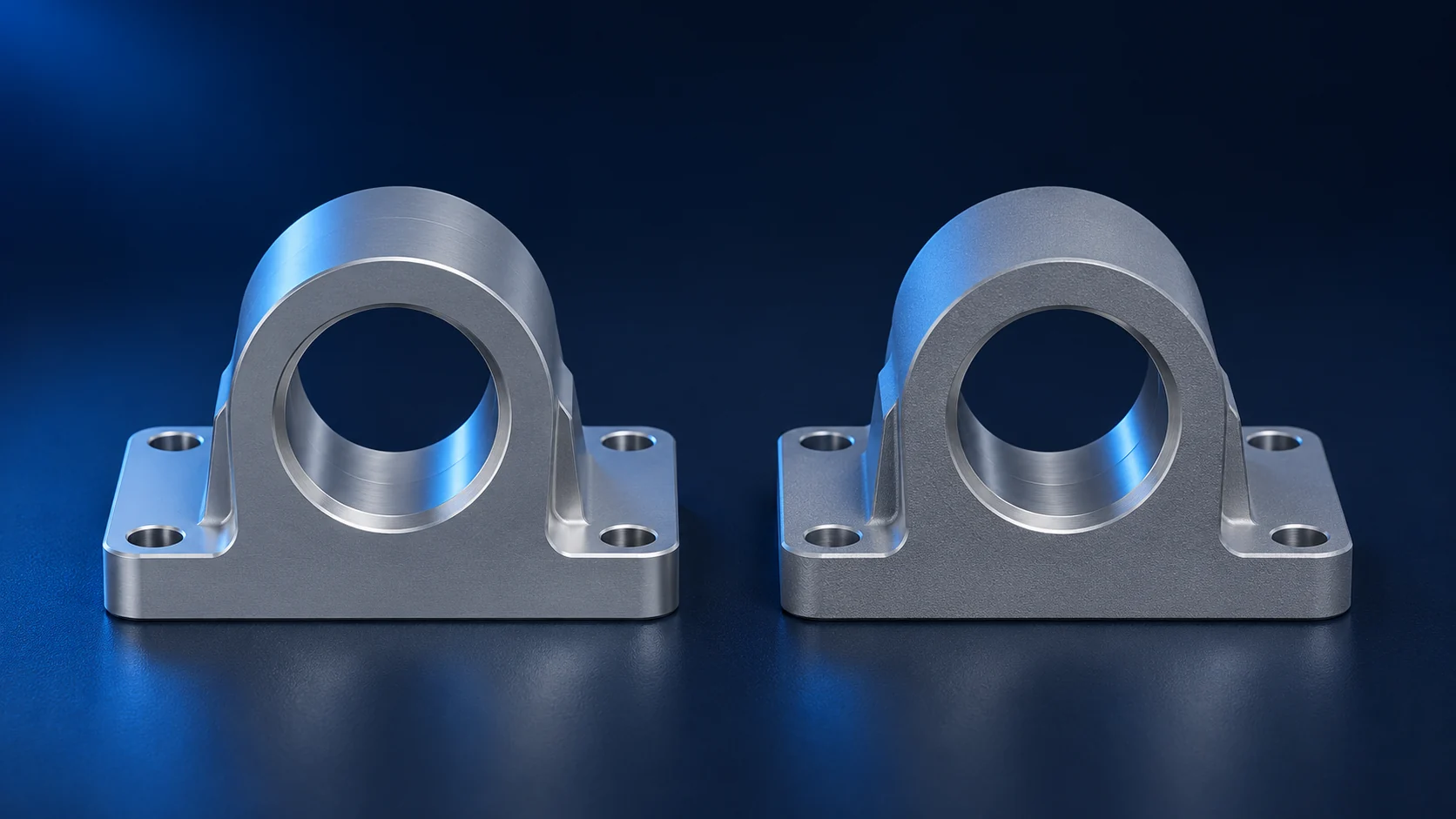
Anodizing preserves the underlying geometry and much of the underlying texture. NASA/JSC’s current PRC-5006 Rev E says the starting surface texture is replicated rather than leveled and that roughness can rise during anodizing and pretreatment. A freshly milled face with cutter marks will not become a polished display surface solely because a color is added. If appearance matters, specify the preparation and the faces to inspect before comparing Type II and Type III samples. A polished, brushed, or blasted starting surface can lead to a different visible result; the finish callout must not hide this upstream operation. [2]
Alloy and temper also matter. MIL-PRF-8625F requires heat-treatable alloys to be in their required heat-treated temper before Type II or Type III anodizing. Its Type III provision restricts certain high-copper and high-silicon compositions unless the contract or drawing provides otherwise. NASA/JSC applies its own approval threshold for high-silicon alloys. The numerical thresholds differ between these documents; they are requirements of the cited specification, not a universal statement that any alloy beyond a line can never be anodized. [1] [2]
For a color-critical machined part, use representative stock of the actual alloy and temper to approve the finish. A coupon made from another alloy, a casting instead of wrought stock, or a different prefinish may not predict the production color. NASA notes that natural Type III color can range from gray to black or dark brown with alloy composition; therefore “hardcoat black” is not enough to guarantee one controlled shade. Class 2 color and its acceptable range must be stated if the appearance itself is a requirement. This is particularly relevant where two separately machined pieces must appear matched after assembly.
There is also a structural reason not to specify thick hardcoat by habit. MIL-PRF-8625F cautions that hard anodic coatings may reduce fatigue strength and calls for that effect to be considered on cyclically loaded parts. That is not a prediction of failure for every bracket. It means a highly stressed rotating or flexing aluminum feature should receive a fatigue assessment for its alloy, geometry, coating, and service condition rather than an unexamined “Type III everywhere” instruction. [1]
Coating thickness changes the finished fit
Anodic oxide occupies material that was aluminum before processing and extends beyond the original machined surface. The term coating thickness refers to the total oxide thickness, not necessarily the outward change of a surface. The Aluminum Anodizers Council gives useful nominal planning ratios: about two-thirds of Type II oxide penetrates the former metal surface and one-third builds outward; for Type III, approximately half is inward and half outward. Actual finished dimensions can differ because alloy, cleaning and etching, bath conditions, feature geometry, and local coating thickness affect the result. [3]
For an accessible bore with Type III, consider a specified 0.0015 in total coating as a planning input. Using AAC’s nominal half-outward relationship, the outward build into the bore would be 0.00075 in on each wall. A bore coated on both opposing walls would then be about 0.0015 in (0.0381 mm) smaller in diameter than its before-finish size: 2 × 0.00075 in = 0.0015 in. The same outward build on two opposite faces would increase an external diameter by about 0.0015 in. This arithmetic is a planning model, not a promise for a particular hole. A pretreatment that removes aluminum can offset some apparent change, and an internal surface may receive less oxide than an open exterior face. [3] [2]
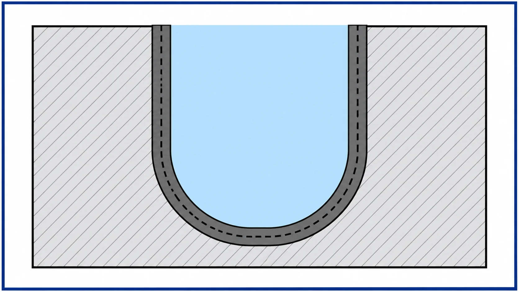
The engineering control is to put the needed finished fit on the drawing, identify whether that feature is to be coated, and agree on the before-coating machining size and inspection state. NASA/JSC recommends specifying both “machine-to” and final dimensions for relevant Type III parts. Its guidance warns that a narrow hole or tube may receive less coating inside than outside, with thickness declining farther into the opening. A blanket 0.0015 in diameter adjustment cannot guarantee a deep bore’s size or protective coverage. [2]
Several routes are possible. A bore may be left coated if the processor can demonstrate the required final fit and coating condition. It may be masked when bare aluminum at that location is acceptable or another approved protection is specified. It may be brought to final size by an approved operation after anodizing, recognizing that material removal changes the coating at that surface. Each route affects the delivered part differently. The drawing should say whether the bore must remain protected and whether its final dimensional requirement is checked after all finishing operations. Our machining-tolerances guide explains the base dimensional callout; the anodizing note must then make clear which dimensions apply after coating.
Threads, edges, masking, and rack marks need feature-level decisions
A thread is not just a cylindrical hole. Oxide on its flanks changes the effective mating geometry, so a nominal growth allowance on the thread’s major diameter cannot prove that a fastener or insert will install at the required torque. NASA/JSC warns that anodizing, especially Type III, is problematic on threads; it notes interference with helical inserts and high fastener running torque even with thinner anodizing. For a fit-critical threaded feature, define whether it is masked, coated and gauged after finish, or treated by another approved route. A mask keeps oxide off the thread but also leaves that aluminum surface without the specified anodic protection unless another treatment is identified. [2]
Edges can be a separate failure point. Hardcoat grows outward normal to a surface, while sharp inside and outside corners can create coating and dimensional irregularity. NASA’s own Type III design section prefers radiused rather than merely broken or chamfered edges for a uniform coating, and gives radius guidance tied to thickness. Those values belong to NASA’s process context; the specific part should be designed with the selected finisher and drawing requirement. If a sharp knife edge is functional, the coating type and acceptance may need to change rather than inventing a radius that destroys the feature. [2]
Anodizing needs electrical contact through a rack. The contact location can leave a small uncoated area or mark. Put it on a noncritical surface when possible and show any prohibited contact faces on the drawing. A datum face, sealing land, visible front panel, or wear track may be a poor place for the mark even when an unseen mounting face can tolerate one. Masking deserves the same specificity: a plug in a bore and a masked broad mating face are different process tasks. State which surfaces must remain bare and why; otherwise a processor cannot tell whether a local absence of oxide is acceptable. [2] For the cost implications of preparation, racking, masking, and lot size after the functional choice is set, see our anodizing-cost guide.
Example: one housing, two defensible coating decisions
Consider a machined 6061-T6 aluminum housing with a visible exterior, one close-fitting alignment bore, a threaded insert hole, and a short guide face touched repeatedly by a mating component. These are hypothetical features used to compare decisions; there is no assumed VETCNC shop process, supplier quote, or universal coating specification. The drawing owner first needs to say whether the guide face is merely touched during occasional assembly or actually operates as a sliding wear surface. That use changes the answer more than the product’s name does.
For an enclosure with occasional handling and no meaningful sliding duty, Type II can be the cleaner choice. If the required outcome is a dyed, consistent exterior plus the specified corrosion protection, call out Type II, Class 2, color and an agreed visible-face standard. Seal it as required by the governing specification. Define the starting texture rather than expecting anodizing to hide milling marks. The alignment bore can be coated only if its finished size and assembly fit are met; otherwise identify masking or an approved final-sizing route. Treat the insert thread separately so installation torque and protection are both resolved. Paying for a wear-first hardcoat would not address any additional requirement in this version of the housing.
For a guide face with a documented abrasion requirement, Type III becomes a credible candidate. Specify the thickness and location needed for the guide surface, then decide whether unsealed hardcoat is appropriate for maximum wear resistance or whether the exposure demands a sealed alternative with an accepted wear tradeoff. Check the mating component, lubrication and debris path as well as the anodized face; the coating designation does not evaluate the full sliding pair. Model and then measure finished bore fit rather than applying one outside-surface growth ratio to a deep hole. Mask or otherwise control the insert thread, set the rack-contact area, and accept the actual natural color or separately qualify a dyed finish if the exterior must match other parts.
These are alternative treatments for the housing, not an instruction to put Type II on one half and Type III on the other by default. A mixed process would need a separately engineered masking and process sequence. If the guide face can instead use a replaceable wear element or a different material, that design may be better than changing the coating on the entire housing. The correct comparison is among designs that satisfy the same fit, environment, appearance and wear acceptance requirements. The answer remains conditional until those functional inputs are fixed.
Write the finish and acceptance state on the drawing
A production drawing should identify the governing specification and edition, Type, Class, color if dyed, and any coating thickness or sealing requirement that is more specific than the governing default. Add the surfaces where thickness matters, visible faces and color range, mask boundaries, prohibited rack-contact areas, and final critical dimensions. State any prefinish surface preparation that changes appearance or function. If coating must remain on a bore or wear face after sizing, that must be explicit. These are not a generic list to add to every simple bracket: each item resolves a real ambiguity for the features present. MIL-PRF-8625F’s acquisition section expressly calls for Type, Class, Class 2 color and uniformity, applicable Type III thickness, special sealing, contact-mark location when important, and conformance criteria. [1]
Separate the coating qualification from final part fit. Under MIL-PRF-8625F, lot conformance inspection includes visual examination, color examination for Class 2, and thickness examination for Type III. Its former dimensional-examination subsection is deleted. Those checks do not, by themselves, verify that the finished alignment bore accepts a pin or that a coated thread meets its gauge and torque requirement. Put the bore or thread’s final inspection on the part drawing or contract and specify whether measurement is before or after finishing. A thickness result on an accessible panel does not prove uniform film in a narrow recess. [1] [2]
For this comparison, the release decision is straightforward. Use Type II when the documented protective and appearance result meets the service condition and fit can be maintained. Use Type III when a real wear requirement warrants hardcoat and the seal, dimensions, alloy, and inspection route have been settled. If neither route satisfies all of those conditions, revise the feature or finish plan before buying a nominal Type or comparing prices.
Type II and Type III anodizing questions
Is Type III simply a thicker Type II coating?
No. MIL-PRF-8625F defines Type II as conventional sulfuric-acid anodizing and Type III by its hard, heavy coating requirements. Type III often has greater thickness and is chosen for wear, but it is a distinct specified result, not a guarantee that the same Type II bath was run longer. [1]
Can Type III be specified in black?
A Class 2 dyed result may be specified when the chosen alloy and process can deliver the required color, but “Type III” alone does not promise black. Natural hardcoat color varies, and sealing or dyeing can change the accepted wear condition. Define the color range and function together; qualify representative samples if appearance is critical. [1] [2]
Should Type III always be left unsealed?
No. Leave it unsealed under MIL-PRF-8625F when maximum abrasion or wear resistance is the main purpose. Where the specified application needs corrosion protection and accepts reduced wear resistance, the order may require sealing. Do not use “hardcoat” as a substitute for choosing that condition. [1]
Will a 0.002 in hardcoat make a bore exactly 0.002 in smaller?
It might be a nominal planning estimate for a bore coated evenly on two sides if approximately half the oxide grows outward, but it is not a guaranteed final dimension. Pretreatment, alloy, local current density and bore depth change the result; narrow holes can coat less inside than exterior faces. Specify and measure the required finished bore. [3] [2]
Technical sources
- U.S. Defense Logistics Agency, ASSIST, MIL-PRF-8625F with Amendment 2: Anodic Coatings for Aluminum and Aluminum Alloy, November 23, 2020, active record checked November 2, 2026. Type and class definitions, Table IV coating thickness, sealing, alloy conditions, acquisition requirements and lot conformance.
- NASA Johnson Space Center, PRC-5006 Rev E: Process Specification for the Anodizing of Aluminum Alloys, listed July 22, 2026, in NASA’s process specification index. Surface preparation, Type III design dimensions, internal coating, threads, natural color and rack contact; NASA-specific requirements apply when this process specification is invoked.
- Aluminum Anodizers Council, Anodized Aluminum FAQ, dimensional-change questions, checked November 2, 2026. Nominal Type II and Type III inward/outward growth relationships and their alloy/process caveats.