Skip to content
VETCNCCNC MANUFACTURING
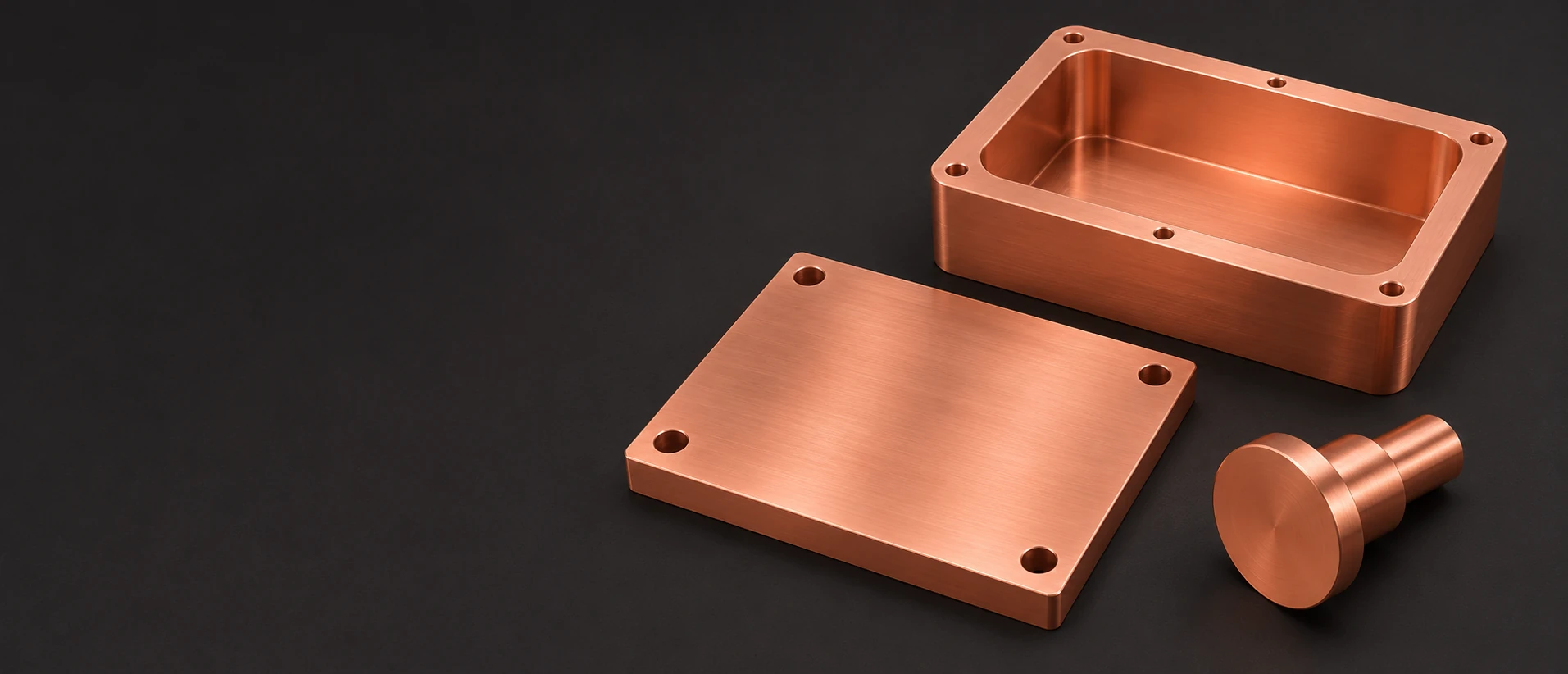
Copper-colored plate, open pocketed body and stepped conductor pin on a dark surface

C10100 Oxygen-Free Copper
CNC Machining

See Cu-OFE Reference Values

Custom OFE Copper Plates, Bodies and Conductors

6 component types

Thermal mounting plates

We mill the mounting face, thickness, hole pattern and specified recesses of an OFE copper plate. Raised lands or local clearance pockets can be included where the supported component and fixing arrangement need different levels.

Pocketed RF bodies

A pocketed copper body combines an internal cavity with cover lands and coupling or mounting features. We machine that drawing-defined geometry, including the specified opening positions and retained walls. Cavity geometry and the complete assembly’s RF performance have separate acceptance requirements.

Bored flange bodies

We turn the central bore, outside register and flange face, with secondary holes or reliefs positioned from the specified references. The body follows the intended joint and mounting arrangement rather than a general flange outside diameter alone.

Feedthrough conductor pins

We turn the metal conductor’s working diameters, shoulders and end connections for the specified feedthrough arrangement. The quote covers the defined copper component; an insulating member, seal and qualified complete feedthrough are included only if separately agreed.

Machined spacer rings

A copper ring can provide a defined bore, axial spacing and flange or stepped profile. We machine the contact and clearance faces for the mating arrangement, including any local relief needed beside the adjacent shoulder.

Conductor mounting blocks

We mill the mounting faces, conductor openings and fastening features of a specified copper block. Hole positions and access pockets can be related to the component’s working face so that the conductor and surrounding hardware reach their intended positions.

This page covers UNS C10100 oxygen-free-electronic copper, also designated Cu-OFE / CW009A. VETCNC quotes its drawing-defined turned and milled components, with the stock form, condition, included surface work and required acceptance identified for the order.

C10100 OFE Copper: Purity, Form and Condition

A defined low-oxygen material basis

CDA identifies C10100 as oxygen-free-electronic copper, with at least 99.99% copper and an oxygen maximum of 0.0005% (5 ppm). This is controlled low oxygen, not literally zero oxygen. The full product specification and required material evidence remain part of the ordered stock definition. [1]

Selection focus
The specified chemistry and impurity basis.

Purity-sensitive electrical and thermal components

Cu-OFE is used where its material purity and conductive properties matter to the design. Cleanliness of a machined cavity or joint face is defined alongside the material, with the supplied surface and any thermal or vacuum requirements. The supplied surface and any later thermal or vacuum requirements are defined alongside the material rather than assumed from the OFE name. [2] [4]

Selection focus
The material requirement and the supplied surface state.

Flat products for plates and pocketed bodies

A suitable flat blank supports a broad mounting plate or a body with a cavity and cover land. The property table below identifies a producer’s rolled-product reference. The ordered plate, bar or other blank must carry its own applicable product and delivery-condition requirements. [2]

Selection focus
The flat product behind the retained faces and walls.

Round products for pins, flanges and rings

Round stock can suit a conductor pin, a bored flange or a spacer with related rotational features. Its required condition follows the actual round product and component. A rolled-strip mechanical table does not become the acceptance basis for that rod simply because both products are C10100.

Selection focus
The round-stock form and its own condition requirements.
Two solid copper-colored rod blanks with visible cut end faces
Plate blank with a pocket footprint and mounting rim beside a supported cavity section

Identify the condition behind each property

The R220 mechanical reference below and the annealed physical values have different stated bases. Mechanical delivery condition and bulk conductivity are not verified by the same observation. Each is evidenced on its own basis: the material record for the delivery condition and bulk conductivity, the dimensional report for the machined part. [2] [1]

Rolled-product mechanical values and typical annealed physical values are kept distinct in this reference.

KME Cu-OFE / C10100: rolled-product and annealed-property references
PropertyPublished valueUnitCondition / basis
Tensile strength, Rm220–260MPaR220; rolled EN 1652 reference
0.2% proof strength, Rp0.2≤140MPaR220; for information only
Elongation, A50≥33%R220; 50 mm gauge length
Vickers hardness40–65HVR220; for information only
Electrical conductivity58.6 / 101MS/m / % IACSTypical; annealed at 20°C
Thermal conductivity394W/(m·K)Typical; annealed at 20°C
Mean linear expansion17.7µm/(m·K)Annealed reference; 20–300°C

KME Cu-OFE datasheet, internal revision October 2020. The first four rows describe its rolled-product EN 1652 R220 reference; proof strength and hardness are expressly informational. Mechanical test temperature and direction are not stated there. The last three rows are typical annealed physical values, with the expansion interval retained. This rolled-product reference is not a rod or pin acceptance specification; the ordered stock form, condition and product requirements govern the component.

Milling and Turning C10100 OFE Copper

Pocket sections retaining backing during bulk removal and final flange and wall machining

Milling faces, cavities and mounting references

We mill the plate faces, pocket geometry and hole pattern from the specified locating basis. A cover land or thermal contact face can remain continuous while adjacent areas receive local relief. Cutter access and pocket corner geometry are resolved without treating every retained edge as a cosmetic blend.

Turning bores, flange faces and conductors

Turning relates a body’s bore, outside register and axial face to its working axis. A conductor pin similarly combines defined seats, shoulders and ends. The specified support and holding areas follow the actual part so that a finished thin flange is not used indiscriminately as the clamping surface.

Release the thin features at the right stage

The cutting sequence retains useful support while adjacent material is removed. A pocket wall or flange can stay connected to a more substantial blank area until the operations requiring that support are complete. The final release and edge work are planned for the geometry rather than assigned one universal minimum wall thickness. [2]

C10100 Mounting Faces, Bores and Axial Fits

Copper locating surfaces and the mating componentConceptual section through a copper bore, locating register and axial face. The drawing defines the size, datums and acceptance state of the working interfaces.Locating registerC10100 copper bodyMating componentInterface concept
A fitted component needs its geometry accepted in the specified support and final-process condition.
Final acceptance by C10100 working feature
FeatureDrawing requirementAcceptance conditionVerification
Mounting plate faceFlatness, thickness and reference areaSpecified free / supported / mounted stateFace geometry and thickness
Flange bodyBore, register and joint-face datumsAfter included final processingDiameter and face relationship
Conductor pinShoulder positions and working profileSpecified final component conditionDiameters and axial dimensions
Pocketed bodyCavity, cover land and opening locationsReleased reference and surface stateCavity / face / feature-location checks

The released drawing defines feature limits and datums. Required surface, cleaning or application tests are identified separately within the order; no vacuum, RF or cryogenic performance result is inferred from a dimensional report.

Final acceptance by C10100 component feature

We quote the mounting face, flange, conductor and cavity requirements from the released component definition. Size, location, surface condition and any specified cleanliness or vacuum tests are separate acceptance items. Tolerance and system qualification are agreed for your component, as separate acceptance items.

Design Details for OFE Copper Bodies and Plates

Pocket corners beside a continuous joint land

An internal corner radius needs clearance for the inserted component without removing the land used by the cover or mating face. A local corner relief may provide that clearance while preserving the rest of the seating perimeter. The drawing identifies the intended contact and relief zones.

Assembly-tool access around a mounting face

Counterbores, fastening holes and an adjacent wall must leave the required path for the assembly tool. A screw that fits its hole may still be inaccessible after the neighboring component is installed. That access is considered in the assembled arrangement, not only in the open machining setup.

Avoid unintended trapped volumes

Where a joint faces a vacuum system, a closed recess, blind fixing or close-fitting overlap can retain gas or cleaning liquid. The design may need an agreed venting or open-through arrangement. We do not add vents to a released part without approval. [4]

Clearance for the specified temperature range

A copper block or ring can move relative to its surrounding assembly as temperature changes. The mating design needs the intended clearance or restraint over its actual range. Room-temperature locating dimensions and a single expansion coefficient do not by themselves resolve that assembly behavior.

Discuss Part Requirements

C10100 Components in Thermal, RF and Conductor Assemblies

A mounting plate in the intended heat path

A plate can connect the supported component to the next thermal interface. Its mounting pattern and any raised pads need to leave the intended path through the retained copper. An opening or relief added for access must be reconciled with that contact area rather than judged only as a machining convenience.

A pocketed body assembled around its internal components

A pocketed RF body must allow the intended insert, cover and connection hardware to be fitted in sequence. A cavity that can be machined from the open top may still need a different access path once the cover or neighboring assembly is present. The released body includes that assembly space without implying an RF tuning result.

A flange body installed at a joint

The body needs an installation and removal path that does not require levering against its joint face. Adjacent fixings and surrounding hardware can govern that path. The machined locating geometry supplies the intended interface; sealing and any system leak acceptance remain separately defined.

A conductor combined with an insulating member

A conductor pin must enter the intended insulating or supporting member without relying on an unspecified assembly force. Lead-in geometry and the installation sequence follow that member’s requirements. The metal component does not by itself establish the insulation, seal or electrical qualification of the assembled feedthrough.

C10100 Surface Condition, Cleaning and Protection

Defined contact land separated from an outer handling zone on a mounting plate

Specified as-machined lands

A joint land, fitted bore or mounting face can remain as machined where it meets its specified texture and edge requirements. The contact zone is identified separately from an external holding or handling area, so marks accepted on the latter do not define the working surface.

Selected finishing without losing the profile

Polishing or another included surface operation follows the defined coverage and texture. It preserves the specified face boundary, corner and locating profile rather than smoothing every transition indiscriminately. Cleaning and protection of that face are specified and recorded as their own steps, alongside the roughness requirement.

Cleaning coverage and the supplied state

The required cleaning route identifies the surfaces and condition to be delivered. For a vacuum-facing part, handling residues and material selection are separate concerns. Any specified cleaning verification or subsequent thermal preparation is included explicitly in the agreed scope rather than assumed from the C10100 grade.

Protection after the required cleaning

The handling and packing arrangement maintains the agreed supplied state on the designated faces. Parts are supported and separated where contact will not mark a working land. Identification is placed outside restricted zones, with the specified protection retained until the agreed handover stage.

C10100 Material, Geometry and Surface Acceptance

Mounting face and through-bore references with separate geometry, material and cleanliness acceptance

Material identity and the ordered product

The record retains UNS C10100, its product specification, supplied condition and source identification. Required chemistry or other material results are tied to that ordered product. A short C101 label on its own is not used to settle an ambiguous designation or certify a different stock form.

Dimensions in the accepted condition

We check the specified faces, bores, shoulder relationships and cavity features in the drawing’s required support and final-process state. A later included thermal or surface step is accounted for in that acceptance stage. A measurement made on the earlier blank is not simply carried forward as the final result.

Defined surface and application tests

Surface texture, required cleanliness evidence and any separately specified application tests follow their agreed acceptance basis. The quotation identifies the included work and responsibility for additional testing. A dimensional pass does not certify an assembled vacuum, RF or cryogenic system.

What Changes the Cost of C10100 Copper Machining?

Product form and material condition

A plate, round blank and deeply pocketed body use material differently. The required product form, condition, impurity evidence and source restrictions affect blank selection and sourcing before the finished geometry is cut.

Retained walls and feature access

A broad thin face, a deep cavity and a bore beside a flange need different support and tool access. The order of cutting and release can add setups beyond the visible number of features. These requirements remain even when the outside component envelope is simple.

Surface state and required records

Selected finishing, an agreed cleaning route, restricted handling zones and required records add defined work. Any additional application testing is quoted within its stated scope. The material’s OFE designation is not used as a substitute for those operations.

Quantity sharing an unchanged definition

Programming, holding preparation and first-part checks can be shared across identical components in one run. Different cavities, conductor ends or surface states retain their own preparation. A repeated part uses the accepted drawing and material-condition basis.

From an OFE Copper Sample to Repeat Components

Resolve the component arrangement

An initial component checks mounting, assembly access and the intended face or conductor geometry. Changes are incorporated into the released definition before the remaining quantity is made to the same arrangement.

Represent the final supplied state

The representative component follows the intended stock condition and included surface or thermal route. Where cleaning and protected handling are required, that supplied state is considered alongside geometry rather than approved from an unfinished rough blank alone.

Release the batch basis

The product specification, drawing revision, condition, surface zones and required acceptance records define the run. Agreed changes become part of that basis so that the production parts do not depend on an undocumented adjustment to one sample.

Control a replacement or repeat

A changed stock form, source, condition or cleaning route is identified against the accepted component definition. This lets the affected material and surface requirements be addressed before a similar-looking replacement enters the same assembly.

C10100 OFE Copper Machining FAQs

Is old British C101 the same designation as UNS C10100 OFE copper?

No. The Copper Information Center’s comparison maps old British C101 to Cu-ETP / CW004A, while Cu-OFE is CW009A. This page’s scope is UNS C10100 OFE. A drawing or purchase order using only C101 needs its intended designation system resolved before sourcing; the short name should not silently turn an ETP requirement into OFE or the reverse.

How can copper have 101% IACS without being more than 100% pure?

IACS is a conductivity comparison, not a purity percentage. Its 100% reference was established for annealed copper at 20°C; modern high-conductivity copper can exceed that reference. The 101% IACS value therefore does not mean 101% copper content. Chemistry and conductivity remain separate requirements with their own reported units and conditions.

Does room-temperature conductivity establish a C10100 part’s cryogenic thermal performance?

No. NIST treats low-temperature copper properties with reference to residual resistivity ratio, or RRR, because purity-related residual resistance affects the result. Low-temperature thermal behaviour is characterised against RRR or another cryogenic measure for the actual supply. If cryogenic performance or a particular RRR is required, that requirement and supporting material evidence must be defined for the actual supply.

Does passing a helium leak test also establish acceptable outgassing?

No. Leak tightness and gas released from surfaces or retained material are different acceptance questions. CERN’s vacuum-acceptance discussion treats leak testing, outgassing and contamination analysis separately. A component or assembly may therefore need more than a leak result when the specification limits its gas load. The required tests and limits belong to that application, not to the C10100 designation alone.

Can the datasheet’s zero bend ratio be applied to a thick machined copper lug?

No. KME’s cited 90° bend-ratio entries are given for rolled strip no thicker than 0.50 mm, with the bend orientation identified. They do not qualify a thick machined lug or another stock form for the same bend. Its geometry, condition and required forming acceptance need the applicable evidence rather than a transferred strip-table entry.

Can a routine protective oil be applied to a cleaned vacuum-facing part?

Only if the specified cleaning and delivery route permits it. Oils and handling residues can introduce contamination and gas load; a protective treatment suitable for ordinary storage is not automatically suitable for a vacuum-facing surface. The agreed handling and packing method must maintain the required supplied state rather than add an unapproved film after cleaning.

PROJECT SUPPORT

Discuss Your C10100 OFE Copper Component

Send the matching drawing and model, full material and product specification, required stock condition and quantity. Identify the working faces, included surface or thermal route and required cleanliness or acceptance records so we can quote the defined component.

C10100 Material and Application References

Named material data and the specific designation, temperature and vacuum-acceptance distinctions used here.

  1. Copper Development Association — Wrought Coppers DatasheetC10100 chemistry and impurity limits, including the oxygen maximum and annealed conductivity note; revision 13 May 2026.
  2. KME — Cu-OFE / UNS C10100 DatasheetRolled EN 1652 mechanical data, informational values and separate typical annealed physical properties; internal revision October 2020.
  3. Copper Information Center — Material Designations and IACSOld British C101 versus Cu-OFE naming, and conductivity expressed relative to the International Annealed Copper Standard.
  4. NIST and CERN — Cryogenic Properties and Vacuum AcceptanceBradley and Radebaugh on RRR-dependent copper properties; Bregliozzi on distinct leak, outgassing and contamination acceptance.
VETCNCCNC MANUFACTURING

Get a Quote

Upload Drawing

*Required fields

Acetal part geometry illustration

Enlarged part geometry illustration

AI-generated part illustration.

English
WhatsApp Email us

Tell us about your project

Share your requirements and we will get back to you by email.

PDF, CAD or ZIP · up to 20 MB