On this page
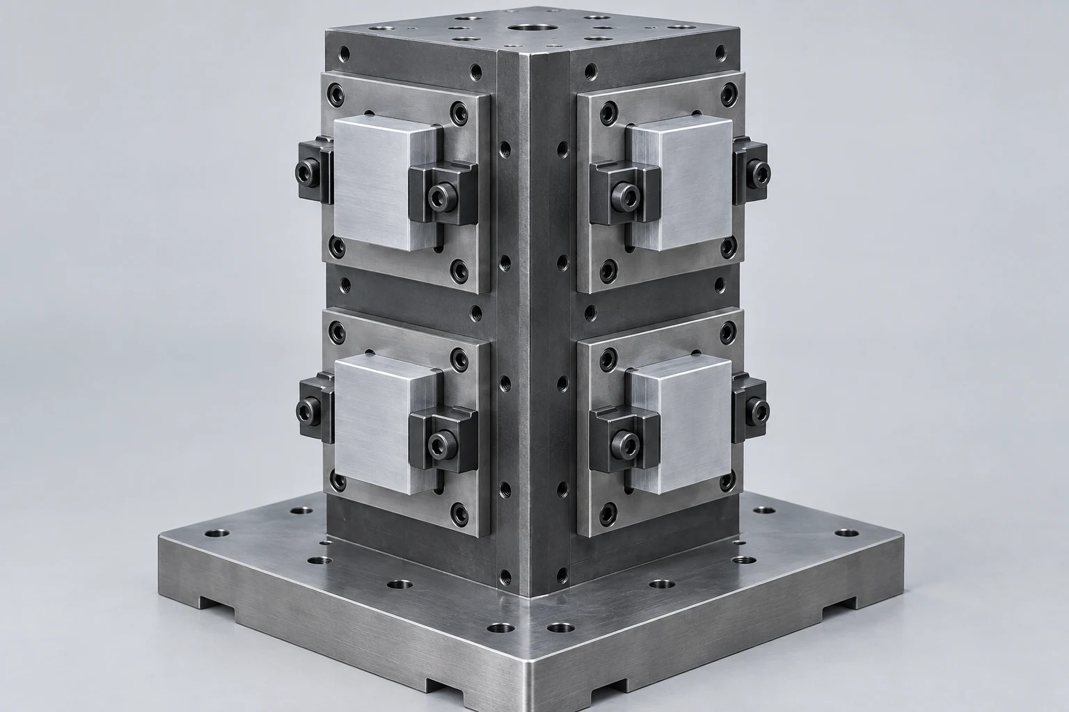
In CNC metalworking, a tombstone is an upright, multi-sided fixture that carries workholding and parts on its faces. It is not a separate type of CNC machine. Its purpose is to organize several workpieces into one loaded arrangement, with suitable access to each station. On a single-spindle machining center, a station-by-station program cuts the parts in sequence; filling more faces does not create more cutting spindles. [1]
A useful tombstone plan explains more than how many blanks fit. It identifies what each station holds, how the part is located, which program coordinates address it, and what comes off the fixture when the cycle ends.
Map the parts before counting the stations
A tombstone commonly appears on a horizontal machining center, where a suitable rotary table presents its faces to the spindle. The comparison of vertical versus horizontal milling explains that orientation. Here, the important unit is the station: one defined place for holding a workpiece through an operation.
Consider a hypothetical square tombstone with four usable faces, A through D, and two stations per face. A1 and A2 belong to face A; the same naming continues through D2. That gives 4 × 2 = 8 loaded part positions, assuming each station carries one part. It says nothing yet about completed parts per cycle.
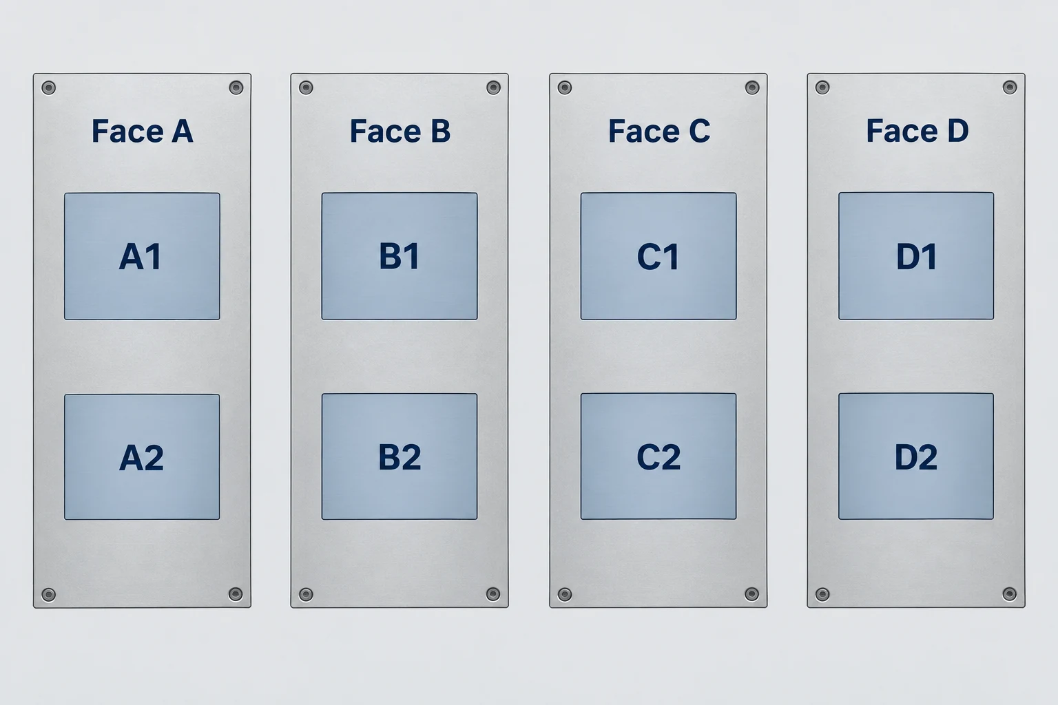
All eight positions might run the same operation. Alternatively, some could hold blanks while others hold parts already machined on another side. In the second arrangement, an occupied station does not necessarily contain a nearly finished part. The process plan must distinguish first-operation output from finished output.
Sequence matters too. CAM systems can order repeated work by setup, operation or tool, depending on the workflow and postprocessor. Grouping a tool’s work across several stations may reduce tool exchanges, but it adds movements between parts. Fewer tool exchanges do not establish the total cycle time. [2]
Give every station a location and an identity
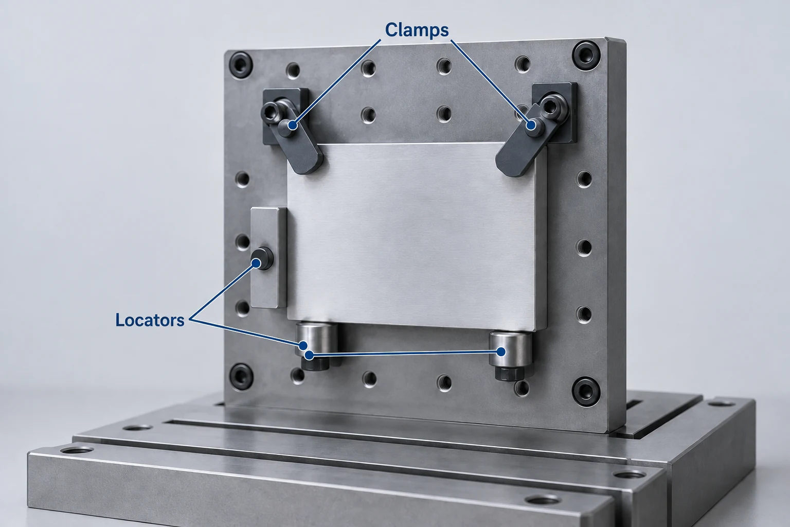
The tombstone provides a common carrier; each workpiece still needs defined locating contacts and restraint. Locators establish position. Clamps hold the part against its intended contacts and resist the machining loads. A mounting hole grid is useful for arranging hardware, but it does not by itself locate the finished part’s functional features. [3]
Follow the reference chain from the machine interface to the tombstone, then to the station fixture and the part. A repeatable carrier connection does not prove that a blank is seated correctly in its own nest. Burrs, chips or an incorrect loading orientation can break that chain at the last contact.
A station label such as A1 is a physical address. A work offset defines a coordinate reference used by the CNC program. Record how the two correspond, including the required indexed orientation. The same part program may be repeated at different offsets, but the control and postprocessor must support the chosen arrangement. An offset cannot correct a part that is wrongly seated or moves during cutting. [2] [4]
| Station record | What to make explicit | Confusion it prevents |
|---|---|---|
| Physical address | Face and position, such as A1 | Checking the wrong nest |
| Part and operation | Part number, revision and incoming state | Loading a finished or partly finished part as a blank |
| Locating contacts | Seating face, stops and orientation feature | Accepting a clamped but incorrectly seated part |
| Program reference | Coordinate assignment and indexed orientation | Running the correct path at the wrong station |
| Unload status | Next operation or finished-part destination | Mixing work in progress with completed parts |
This is a record structure, not a controller setup recipe. Keep it consistent with the actual fixture, program revision and inspection plan.
Check the complete loaded fixture
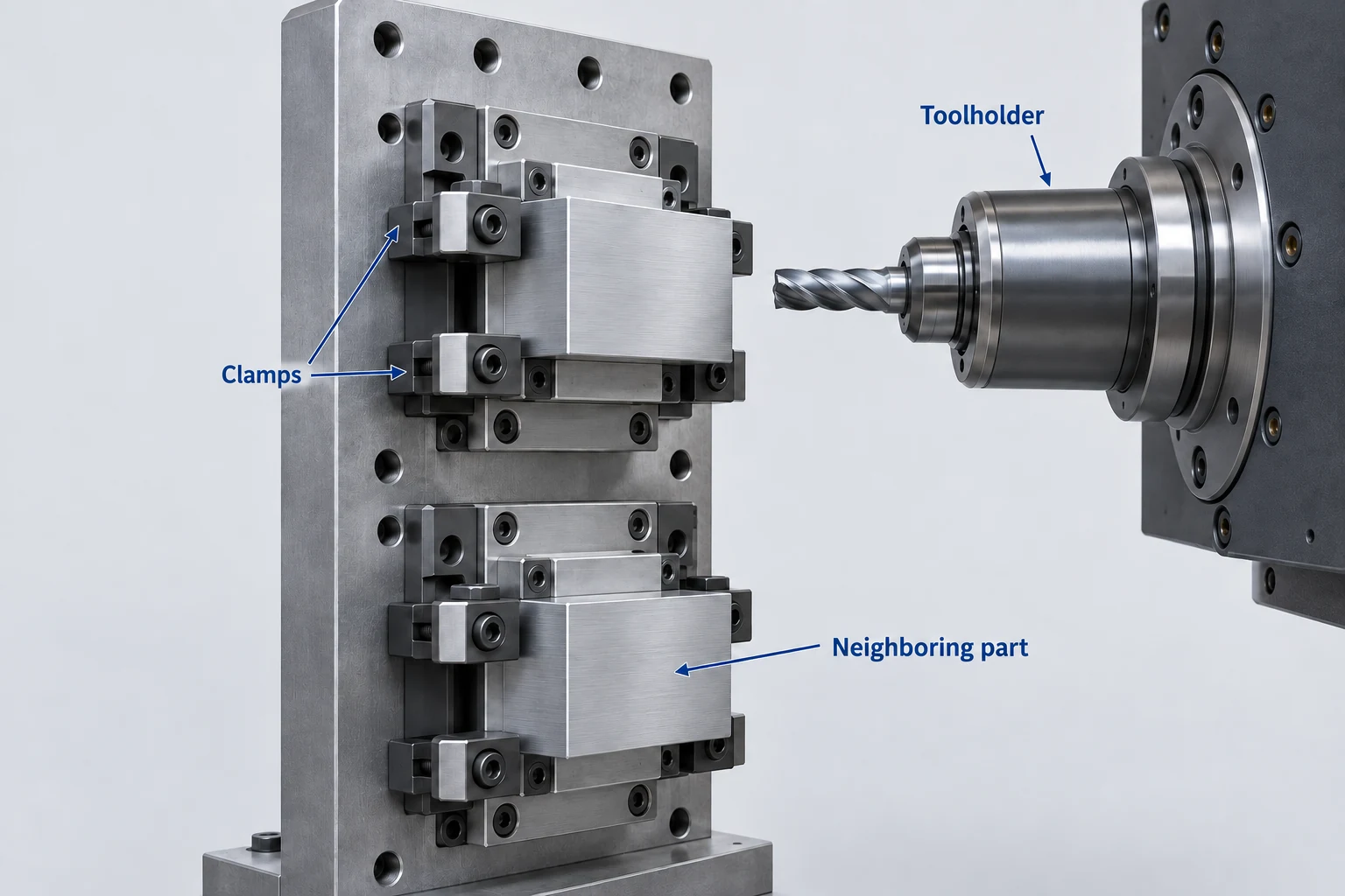
Do the space review with blanks and clamps installed. Include every projecting fastener, locator and neighboring workpiece, as well as the tombstone body. A station can be reachable in isolation yet become obstructed once the adjacent position is filled.
Check the full tool assembly. The cutter may reach a feature while the wider holder approaches a neighboring part or clamp. Review entry, withdrawal and travel between stations, plus the route used to index the loaded fixture. Clear cutting positions at two faces do not prove that the intervening motion is clear. [5]
The load review also includes the carrier and all workholding, not just the parts. Haas’s pallet-pool documentation, for example, states its payload in terms of workpiece plus workholding and defines a fixture-and-workpiece envelope. Use the limits and load conditions for the actual machine, rotary and pallet arrangement. [6] Our guide to reading machining-center specifications explains why travel and load ratings answer different questions.
Leave a credible exit for chips and access for cleaning the locating contacts. Upright parts can help chips fall away, but ledges and lower stations can collect them. More tightly packed parts may therefore create cleaning and seating problems even when the cutter paths fit. Carr Lane’s fixture guidance treats chip clearance and repeatable location as connected design concerns. [3]
Keep loading and part status unambiguous
Plan the loading routine around the station map at a designated loading position, under the machine’s prescribed operating procedure. This does not imply access to work inside an active machining cycle.
- Remove the assigned output.
- Clear the seating contacts.
- Place the correct incoming part.
- Confirm its seating and clamp condition.
A compatible pallet system may provide a separate loading station with its own program and scheduling controls. A tombstone alone does not provide that station or guarantee unattended production. [6]
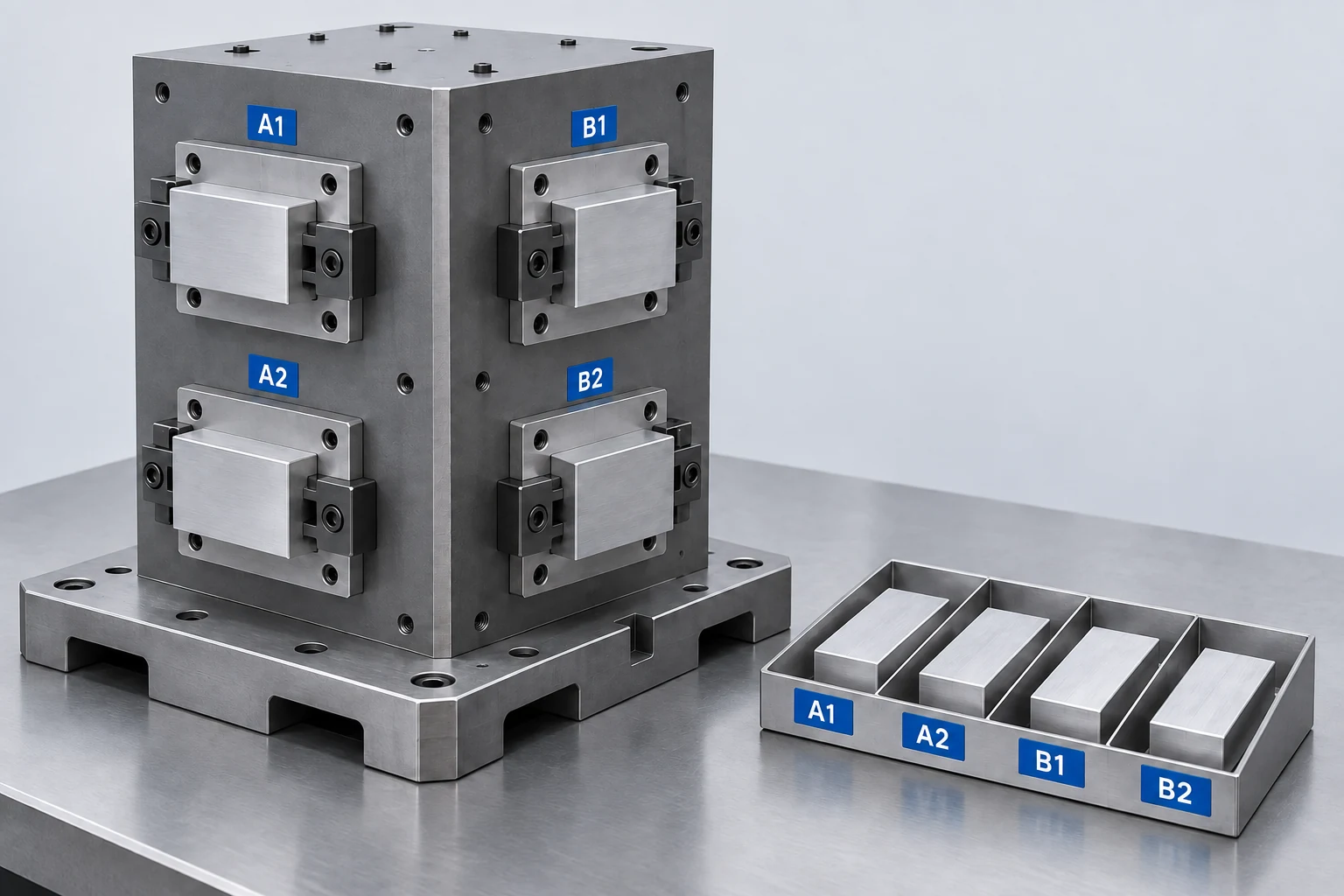
Decide how a missing blank or disabled station is handled before running the job. The physical load and the selected program must agree; simply leaving a position empty does not tell the control to omit that station’s operations. Do not improvise the omission by assuming every intervening move is harmless. [2]
Keep the station identity when investigating a result. If a location-related issue repeatedly follows A2 while other stations remain consistent, that pattern helps direct checks toward A2’s contacts, coordinate assignment and loading condition. It does not diagnose the cause by itself. Likewise, separate parts awaiting another operation from those ready for final inspection.
For a purchased component, the useful discussion is how the proposed arrangement maintains the drawing’s feature relationships and yields the required delivered parts. VETCNC’s CNC milling service connects those part requirements with machining, inspection and delivery scope.
CNC tombstone FAQ
Can a tombstone be used on a vertical machining center?
Yes, when the machine and fixture arrangement provide the required access, support and clearance. An upright multi-sided fixture does not automatically present all its faces to a downward-pointing spindle; the setup needs a suitable way to reach each required surface. [7]
Can different part numbers share one tombstone?
They can, if the fixtures, program, tool set and loading plan support the combination. Keep each station’s part number, revision and operation explicit. Similar-looking parts are not interchangeable merely because they fit the same nest.
Does an eight-station tombstone deliver eight finished parts per cycle?
Only if all eight loaded positions complete their required manufacturing route in that cycle. Stations assigned to intermediate operations produce work in progress. Empty positions, inspection outcomes and later operations also affect the completed quantity.
Does each tombstone face need only one work offset?
There is no universal one-offset-per-face rule. Every programmed instance needs the correct coordinate definition. The number and use of offsets depend on the fixture layout, CAM output and controller functions; the station map must match that implementation. [2]
Technical sources
- Hennig. Stallion Tombstones. Multi-sided workholding structures and rotary access.
- Autodesk Fusion Help. Post Process tab reference. Work-coordinate instances and operation ordering.
- Carr Lane Manufacturing. Guide To Locating & Clamping Principles. Location, restraint and chip clearance.
- Haas Automation. Mill Operator’s Manual — Part Setup, Sections 8.5–8.6. Work and rotary coordinate references.
- Rana Udayveer Singh, Autodesk. How to Leverage Collision Detection During Machine Simulation in Autodesk Fusion. Machine, stock, holder and fixture checks through simulated motion.
- Haas Automation. 6+1 Pallet Pool. Complete payload, loaded envelope and pallet scheduling.
- Carr Lane Manufacturing. 3+1, 3+2, and Simultaneous 5-Axis Machining. Indexed access and compatible rotary configurations.



