On this page
Quick Engineering Answer: To keep CNC machined aluminum heat sinks affordable and chatter-free, keep fin thickness ≥0.8–1.0 mm, fin gap ≥2.5–3.0 mm, fin height-to-gap ratio ≤4:1–6:1, and hold tight ±0.01–0.02 mm flatness strictly on the thermal-interface mounting base.
Design a CNC-machined aluminum heat sink from the heat it must remove, the air it will actually receive, and the contact surface that carries heat into its base. Calculate the allowable sink-to-air thermal resistance first. Then lay out fins and mounting features around cutter access, remaining base material and the real airflow path. A CAD model with more fins does not prove a lower device temperature; the finished heat sink must be tested in its assembled system.
The design problem is not simply “how thin can a fin be milled?” A narrow channel may increase nominal area while forcing a long, flexible tool, trapping chips or increasing air resistance. A thick base may support machining but spread heat poorly if the source footprint and contact are wrong. The sequence below connects a thermal target to a machinable candidate and an acceptance test.
Turn the device limit into a sink-to-air target
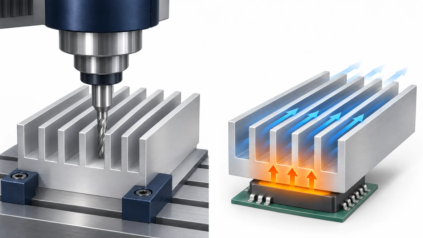
For a device whose principal heat path is through its top case into a heat sink, a first-pass series model is Tj = Ta + P(θJC + θCS + θSA). Here P is heat dissipated by the device in watts, Tj is junction temperature, Ta is inlet-air temperature at the heat sink, θJC is junction-to-case resistance, θCS is the case-to-sink interface, and θSA is the heat sink’s resistance to that air. Texas Instruments explains this decomposition in Understanding Thermal Dissipation and Design of a Heatsink. Use dissipated heat, not the electrical input power of a larger system.
Suppose a top-cooled device has the following design inputs. In an actual design, take the device limits from its data sheet and the air and interface conditions from the installed system.
| Design input | Value | Where the design needs it |
|---|---|---|
| Device heat loss, P | 20 W | Worst sustained operating condition to be cooled |
| Maximum junction temperature, Tj,max | 105°C | Device requirement |
| Air entering the fin field, Ta | 40°C | Installed-system condition, not room temperature by default |
| Junction-to-case resistance, θJC | 1.2°C/W | Applicable package path and data-sheet condition |
| Case-to-sink interface, θCS | 0.3°C/W | Specified interface material and mounting condition |
The total allowable junction-to-air resistance is (105 − 40)°C / 20 W = 3.25°C/W. Subtracting the package and interface leaves θSA ≤ 3.25 − 1.2 − 0.3 = 1.75°C/W. At that boundary the sink reference temperature would be 40 + 20 × 1.75 = 75°C, the case would be 81°C after the 0.3°C/W interface, and the junction would be 105°C. The arithmetic gives a performance target for the assembled flow condition; it does not size the fins.
One changed input can overturn the design. If the air entering the channels is 50°C at the same 20 W and the other resistances are unchanged, θSA must be ≤ (105 − 50)/20 − 1.2 − 0.3 = 1.25°C/W. Reusing a 1.75°C/W selection because the room itself remains at 40°C would miss the hotter air already inside the enclosure. The fan, neighboring devices, duct and vents determine that inlet condition. A candidate designed exactly to the numerical limit also leaves no allowance for interface, fan, power and production variation; set a project margin before freezing geometry.
This series calculation is appropriate only when the specified θJC describes the dominant top-side path. Some packages send substantial heat into the board, and several components can heat one common sink. Texas Instruments’ processor thermal guide limits the simple equation to cases where most heat can leave through the lid; more complex systems need a thermal model and system test. Do not subtract a data-sheet θJA from this sum as if it were a detachable package resistance.
Design the heat-source footprint and mounting face before the fins
The 20 W enters through a finite contact patch, not the entire 60 × 70 mm base in the example below. A small centered package requires heat to spread laterally through the base before reaching remote fins. Mounting holes, counterbores, cable pockets and weight-reduction recesses can interrupt that path. Put them on the model together with the actual heat-source footprint; a visually even fin pattern is not evidence of even base temperature.
The interface resistance assumed above depends on the thermal interface material, bond-line thickness, contact area, surface finish, flatness and mounting pressure. TI and Boyd both describe these dependencies. That means the drawing should identify the contact land and its condition after finishing, the mounting-hole pattern and any features that set compression. A nominal “flat bottom” callout with no defined contact region will not establish the 0.3°C/W used in the calculation. Likewise, a thick grease layer applied in an ad hoc test is not the production interface.
Keep the mating face protected during slot milling and deburring. A burr at a hole or slot edge can hold the base off the device even if a flatness measurement elsewhere passes. A spot face or local relief may be useful where a fastener head or component package would otherwise interfere, but the relief must not remove the required heat-contact land. The aluminum machining page covers stock, alloy temper and general machined-part finish considerations; the heat sink’s interface and thermal budget remain specific to this assembly.
Choose fin direction and spacing for the installed air path
Before choosing pitch, decide whether the unit relies on natural convection or a fan, and draw the air’s entry and exit around the actual mounted heat sink. Straight, open channels aligned with the forced-air path make a different flow problem from fins inside a partly closed enclosure or a sink rotated against the natural buoyancy direction. Boyd’s heat-sink selection paper states that useful planar-fin spacing depends strongly on flow velocity and fin length in the flow direction. It offers condition-specific guidance, not one fin-gap-to-height ratio for all designs.
A fan’s free-air CFM is not the flow delivered through the channels. The installed operating point lies where the fan curve meets the system-resistance curve, as fan maker ebm-papst explains. A restrictive inlet, filter, neighboring PCB, short circuit around the sink or narrow fin channels can change the actual flow. Even a fan with adequate catalog volume can bypass the fins if the enclosure offers an easier path. Record the expected operating airflow or the fan/system curves and the physical duct arrangement before predicting θSA.
More nominal area is not automatically more effective area. Tall fins can remain cooler near their tips because heat has to conduct up from the base. Closer fins add wetted area but can restrict flow and complicate chip removal in a machined one-piece construction. Longer channels give air more residence length, but the air warms as it travels. Compare candidate geometries with a method appropriate to the application and then test the installed prototype; do not infer a temperature drop from fin count alone.
Check the fin layout against cutter reach, not a universal fin ratio
Consider a 60 mm net fin-field width after separate mounting ears have been reserved, with 70 mm flow length, a proposed 5 mm base and 18 mm fin height above the base. Assume parallel fins 3 mm thick and equally wide open channels. If N fins leave N − 1 channels of width g, the occupied width is 3N + g(N − 1) millimeters. This is a fit calculation only; the base and fin dimensions still need thermal and mechanical evaluation.
| Candidate | Fin-field fit | Top-entry end-mill access | Thermal question left open |
|---|---|---|---|
| 4 mm clear channels | 9 fins · 8 channels · 59 mm occupied | 18/4 = 4.5 depth/width; end mill ≤ 4 mm | More area; flow restriction to verify |
| 6 mm clear channels | 7 fins · 6 channels · 57 mm occupied | 18/6 = 3 depth/width; wider cutter possible | Less area; actual airflow to verify |
The fit arithmetic is 9 × 3 + 8 × 4 = 59 mm versus 7 × 3 + 6 × 6 = 57 mm. The 4.5 and 3 figures above are channel depth divided by clear width. They are not approved cutter length-to-diameter limits. If a 3 mm cutter is required in the 4 mm channel, its 18 mm fin-height reach is already 6 tool diameters before extra stickout or shank clearance. A cutter cannot be chosen solely by nominal gap: tool neck, holder, corner radius, entry path and evacuation space must clear the fins. Harvey Performance’s thin-wall milling guidance specifically calls out long-tool deflection, chatter, stock support and staged cutting. The CNC milling design guide covers these general access principles; here they govern a particular thermal geometry.
Leave a realistic way to cut the channels. Open ends allow the tool and chips to enter and leave along the slot; blocked ends require an internal entry and a cutter-radius-compatible end. A slot that narrows under an overhang is not reachable by a normal straight end mill from above. If a fastener boss crosses a channel, decide whether the airflow interruption and extra setup are acceptable. These are drawing changes to evaluate with the thermal model, not changes a machine shop should silently make to meet a preferred tool size.
Fin straightness also changes as stock is removed. A 3 mm-wide, 18 mm-tall fin can bend under cutting force or clamping if the adjacent material is removed all at once. Alternating or staged cuts can keep more supporting stock until later passes; lighter final cuts can reduce side load. The feasible method depends on actual tool geometry, machine, fixture and material condition. This is why an apparent 1 mm reduction in gap may carry a large process change even before the airflow calculation is revisited.
Decide whether one-piece milling is the right fabrication route
A “CNC machined heat sink” may mean a fin field milled from solid stock, or an extruded profile whose contact face, mounting holes and local features are subsequently machined. The buyer should specify the needed final geometry and thermal result, then compare routes. Boyd’s fabrication guide describes extruded profiles with secondary machining, skived fins and bonded-fin bases; the actual tradeoff depends on the dimensions and volume of this design. Generic route claims such as “machining is always best for prototypes” or “extrusion is always cheaper” leave out die cost, available profiles and required secondary work.
| Route | When it deserves evaluation | Critical drawing or test check |
|---|---|---|
| One-piece milled block | Local geometry or frequent design changes | Every-slot access; fin straightness; base contact; thermal test |
| Extruded profile plus machining | Constant fin section; cut length; local features | Profile and temper; machining datum; contact face |
| Skived or bonded fins | Pitch or height difficult to mill or extrude | Joint if present; stability; airflow; thermal test |
A change of process is not permission to change the thermal specification. A skived one-piece fin and a bonded fin have different paths from fin to base; an extrusion’s alloy and temper may differ from a machined plate. Compare the complete assembly at the same heat load and airflow. If the 4 mm-channel milled candidate is costly to make but the 6 mm candidate cannot hit the thermal target, that is a reason to evaluate another fabrication route, not to declare either candidate acceptable without test.
Release the dimensions and surface conditions that control function
Separate the drawing’s functional controls from every nominal CAD dimension. For this example, that means identifying the device-contact land and its datum, finished contact surface condition, hole pattern and clamp or interface geometry, base thickness at the heat source, fin height, fin thickness and channel clear width, overall envelope, and the entrance/exit orientation of the fin field. State alloy, temper and stock form. A material data sheet for 6061-T6 or 6063-T5 cannot replace certification of the supplied stock, nor does its bulk conductivity establish the assembled sink’s θSA.
Inspect the contact face in the condition in which it will be installed. Burrs at tapped holes, raised edges from deburring, warped bases and fins bent into a channel can each affect fit or flow. If a finish or coating is specified, mark surfaces that need masking or a different final condition. Measure critical clear widths after the final treatment if that treatment changes them. Avoid adding an unsupported universal flatness, roughness or fin-wall tolerance; set limits from the thermal interface, mounting method, fit and actual validation data.
State how the part will be located during inspection. A base held flat by a vise may spring after unclamping. A mating-face report should therefore use the agreed support condition and relevant datums. The aluminum machining cost guide addresses general material-removal and setup drivers; the more important heat-sink choice here is whether the needed thermal geometry survives those manufacturing and inspection constraints.
Validate the finished sink in the assembled cooling system
First inspect the released part: alloy/temper evidence if specified, contact land, hole location, fin and channel dimensions, clear entry/exit, burrs and damage. Those checks show that the candidate was built as intended. They do not show that a device remains below 105°C. Thermal acceptance requires a separate assembled test or validated system analysis with the actual interface material and application pressure, fan or natural-convection orientation, enclosure, heat load and inlet-air condition.
- Reproduce the design load. Run the device at its defined sustained 20 W dissipation, or at the actual worst operating profile if heat is time-dependent. Electrical supply power is not automatically device heat loss.
- Measure the environment that the fins receive. Record inlet-air temperature close to the heat sink and the fan operating state. A 40°C room cannot stand in for a 50°C channel inlet.
- Measure the specified temperature safely. Use the device’s qualified junction telemetry or a validated case-temperature method for that package. Texas Instruments warns that a sensor or thermocouple installation can disturb the heat path and that bare-metal infrared readings need emissivity care.
- Hold the assembly in the required condition. Use production interface material, mounting hardware and clamp condition. Allow the defined steady state, or measure the specified transient peak if the duty cycle makes steady state irrelevant.
- Compare with the thermal requirement. In this example, a 20 W test at 40°C inlet must demonstrate the applicable junction-temperature limit of 105°C or less under the approved test and uncertainty rule. Check the hotter inlet and manufacturing variation before release.
For a simple top-path prototype, a measured sink-reference-to-inlet rise divided by measured device heat can estimate effective θSA, but it requires a defined reference location and actual heat partition. The direct system verdict is the device temperature under the specified operation. Texas Instruments’ thermal-design guide notes that finalized-system case measurement and power conditions matter; a bare heat-sink data-sheet resistance measured in an open test fixture does not by itself prove the installed junction temperature.
CNC-machined aluminum heat sink questions
Will more machined fins always cool a device better?
No. More fins increase nominal area but also narrow passages, change pressure drop and demand thinner walls or narrower cutter access within a fixed width. Compare the candidate with the installed airflow and heat-source path. Nine fins in the 60 mm layout above are not automatically better than seven.
How small can a gap be for a milled heat-sink fin field?
A minimum gap cannot be set from fin thickness alone. The specified width must admit a cutter, holder clearance and chip path to the full slot depth while leaving each fin stable. Tool access also depends on channel length, open-end entry, alloy/temper and the inspection requirement. The 4 mm layout above requires a substantially different reach check from the 6 mm layout.
Should I specify 6061 or 6063 aluminum?
Specify the alloy and temper with the chosen stock and fabrication route. A milled plate and an extruded profile may arrive in different conditions, and bulk thermal conductivity alone does not settle fin airflow, interface resistance or mounting stability. Evaluate both routes against the same installed thermal target and drawing requirements.
Does black anodizing guarantee a better heat sink?
No. Surface finish can affect radiation and appearance, while the result in a forced-air assembly also depends on channel flow and the interface. State where the coating belongs and which contact or electrical surfaces must remain in their specified condition, then test the finished assembly. A color choice is not a measured θSA.
Frequently asked questions
What is the minimum practical fin thickness and channel gap for CNC milled aluminum heat sinks?
Keep fin thickness ≥0.8–1.0 mm and channel spacing ≥2.5–3.0 mm (with fin height ≤4×–6× channel width) so standard carbide end mills cut cleanly without fin bending or chatter.
Is 6063-T5/T6 better than 6061-T6 for CNC machined heat sinks?
6063 offers ~200 W/m·K thermal conductivity (~15–20% higher than 6061-T6’s ~167 W/m·K), while 6061-T6 is slightly easier to mill cleanly with burrs and readily stocked in thick billet plate—compare both if thermal budget is tight.
When should a heat sink be CNC machined vs. extruded or skived?
CNC machining wins for 1- to 300-piece prototypes, complex 3D mounting bosses, integrated liquid channels, and zero tooling cost; extrusion + secondary CNC wins at 500+ identical constant-profile units.
Does anodizing help or hurt aluminum heat sink thermal performance?
Clear or matte black Type II anodizing adds negligible thermal resistance while markedly increasing radiative heat emissivity and protecting fins from oxidation (keep the chip contact base masked bare for optimal TIM contact).
Technical sources
- Texas Instruments, Understanding Thermal Dissipation and Design of a Heatsink (SLVA462, 2011). Supports the junction-to-case, interface and sink-to-air resistance model and dependence on airflow and interface conditions.
- Texas Instruments, Thermal Design Guide for DSP and ARM Application Processors (SPRABI3B, 2017), and Semiconductor and IC Package Thermal Metrics (SPRA953D, 2024). Limit the simple top-path model and describe installed-system temperature measurement.
- Boyd, How to Select a Heat Sink, by Seri Lee. Explains thermal-circuit inputs, airflow, flow length, fin spacing and conditions behind performance curves.
- Boyd, Heat Sink Fabrications Guide (May 2025). Describes extrusion with secondary machining, skived fins and bonded-fin construction; its product-specific ranges are not CNC capability specifications.
- ebm-papst, Fan Performance FAQ. Explains fan and system-resistance curves and the installed operating point.
- Harvey Performance, Your Guide to Thin Wall Milling. Explains cutter reach, wall support, deflection and staged cutting; the maker’s method is technical context rather than a VETCNC process claim.