
Mounting plates
Through-hole patterns connect a plate to a mating frame. We keep the locating faces and the bolt pattern in the same manufacturing definition, including any separate dowel features.
Discuss a mounting plate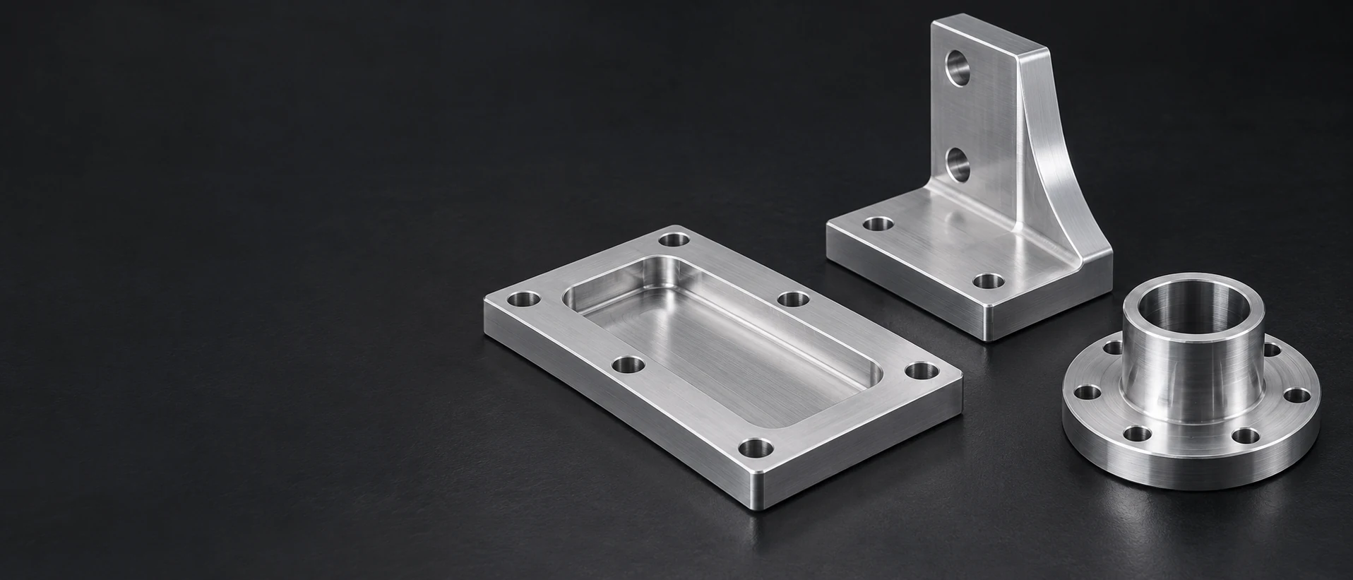
We drill mounting patterns, blind holes and intersecting passages in custom metal and plastic parts. Hole diameter, location, usable depth and edge condition define the finished feature; reaming, boring, threading and bolt-head seats are separate operations when the drawing requires them.
The hole serves the surrounding part. We relate its entry face, exit and axis to the mounting, fastening or fluid-routing job it performs.
Through-hole patterns connect a plate to a mating frame. We keep the locating faces and the bolt pattern in the same manufacturing definition, including any separate dowel features.
Discuss a mounting plate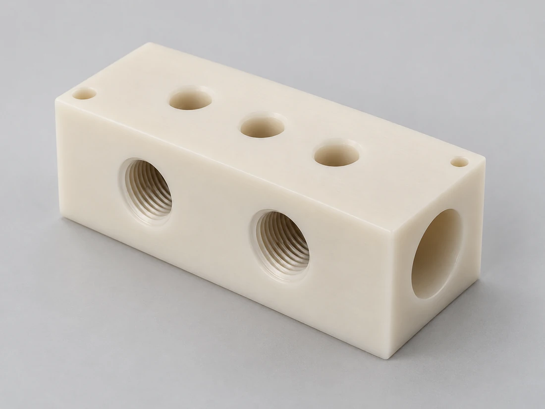
Drilled holes prepare a block for tapping or thread milling. The usable thread length and space below it determine the required preparation depth; a drilled pilot alone is not a finished threaded port.
Discuss a threaded block
Radial openings can connect to the axial bore of a sleeve or coupling. Their axial position and clocking relate to its locating features; any required thread is completed after hole preparation.
Discuss a radial opening
Ports on different faces form an internal route. We distinguish the flow passage from its sealing seat, threaded connection and closure so each receives the operation it needs.
Discuss a port block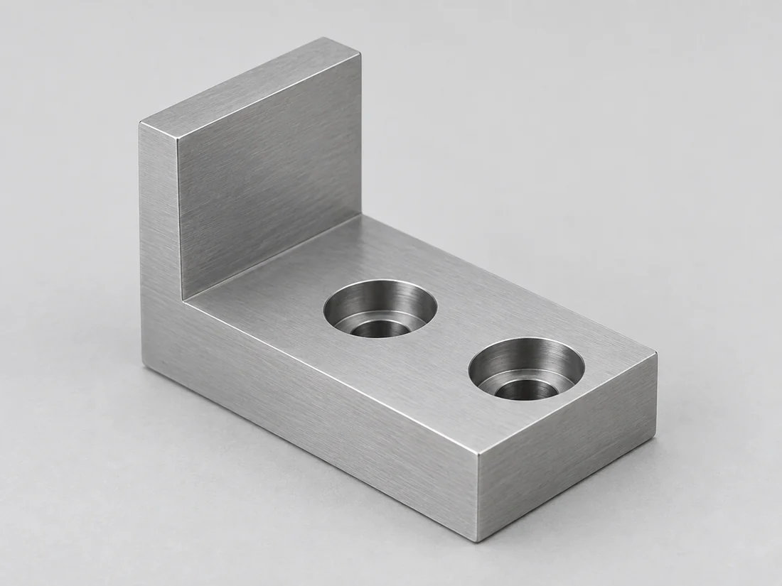
A clearance hole passes the screw shank while a counterbore recesses the head. The bearing shoulder and remaining wall below the recess are distinct features of the mounting detail.
Discuss a mounting block
Fixing holes surround the flange’s main axis. Their pitch-circle location and the room around each hole determine how the flange aligns and how the fastener can be installed.
Discuss a drilled flangeA drilled opening can be the final feature or the starting geometry for a more controlled interface. We identify that distinction before cutting.CNC boring enlarges and finishes an existing hole when its size, form or axis relationship needs a separate operation.
We create the specified opening from an accessible face. Through holes need an exit-edge definition; blind holes need a clear distinction between cylindrical depth and the remaining drill-point space.
Entry • depth • breakthrough
A pilot for tapping, a hole left for reaming and a completed clearance hole have different finished states. We include the required secondary operation in the part scope instead of treating all drilled holes as interchangeable.
Drill • size • thread
Holes on different faces share a datum system when their axes must meet or align. Locating and reorienting the part becomes part of the manufacturing route, especially where an exterior edge does not control the assembly.
Datums • orientation • access
Sandvik Coromant’s drilling guidance identifies uneven entry forces, cross-hole chip evacuation and internal deburring as separate process problems. Their practical consequence is a hole route suited to the actual geometry.

A drill entering an uneven surface can engage one side first and deflect. A local flat can provide a more balanced start where the part geometry allows it. A prepared entry pad can be made by CNC milling while retaining the drawing’s hole axis and the surrounding functional surface.
A conventional pointed drill leaves a cone below the full-diameter cylinder. A screw, pin or insert needing clearance at full diameter cannot use that cone as extra cylindrical depth. A flat-bottom requirement calls for a suitable finishing operation.
Where two passages meet, the intersection can retain a burr and redirect chips. We consider which opening gives access to that edge, so a buried cross-hole is reached and verified.
Breakthrough can push a thin exit wall outward. Supporting the local wall and inspecting the released part help distinguish a sound hole from one that only appears correct while held flat in a fixture.
Material condition affects cutting response and the state in which a hole is measured. The references below inform dimensional planning and support; they are material data, not drilling tolerances.
| Material | Grade / condition | Reference property |
|---|---|---|
| Aluminum | 6061 extrusion | CLTE 23.6 µm/(m·K), 20–100°C |
| Stainless steel | 316L / EN 1.4404 | CLTE 16 µm/(m·K), 20–100°C |
| Alloy steel | 42CrMo4 +QT; Ovako 327A, round bar 40 < d < 100 mm | Hardness 270–320 HB |
| Brass / copper | C36000 / C11000 | CLTE 20.5 / 16.9 µm/(m·K), 20–300°C / 20–100°C |
References: Hydro Alloy 6061; Outokumpu Supra range; Ovako 42CrMo4; Copper Development Association C36000 and C11000. CLTE is the typical coefficient of linear thermal expansion over the stated interval; hardness applies to the stated bar condition and diameter.
| Material | Grade / test | Reference property |
|---|---|---|
| POM-C | TECAFORM AH natural; ISO 527-2, 1 mm/min | Tensile modulus 2,800 MPa |
| PA6 | TECAMID 6 natural; ISO 62, 23°C | Water absorption 0.30 / 0.60%, 24 / 96 h |
| PEEK | TECAPEEK natural; ISO 527-2, 1 mm/min | Tensile modulus 4,200 MPa |
Typical values from Ensinger TECAFORM AH natural, TECAMID 6 natural and TECAPEEK natural product data. Modulus: ISO 527-2; water absorption: ISO 62. Stiffness affects support during machining; moisture response matters when selecting the inspection and service condition.
Thermal expansion matters when a warm part is compared with a drawing limit. Polymer stiffness and moisture response also affect support and measurement state. We retain the specified grade and condition in the part definition.
The final operation must preserve the surface that seats, locates or seals the mating component.
We remove burrs to the specified edge condition without turning a narrow bearing or sealing land into an uncontrolled chamfer. A defined edge break is kept distinct from a countersink that seats a fastener head.
Internal chips and loose burrs need a removal route through the connected openings. Cleanliness requirements belong to the delivered part; passage cleaning alone does not demonstrate leak tightness or hydraulic performance.
Coating build-up or material removal can change a finished hole. Masking, allowances and any final sizing operation must place acceptance at the required delivered condition.

We inspect the specified feature rather than infer every requirement from drill diameter. A correctly sized hole can still be misplaced, too shallow or obstructed at an intersection.
Hole size, axis location and usable depth answer different assembly questions. The inspection route follows the drawing and the accessibility of the feature.
ISO 273 provides general-purpose bolt-clearance diameters in fine, medium and coarse series. Selected fine and medium values appear below; they do not define the location of the hole pattern.
| Feature | Assembly question | Inspection basis |
|---|---|---|
| Hole diameter | Does the mating shank or prepared tool fit? | Specified diameter and size limits |
| Pattern location | Do the axes meet the mating pattern? | Drawing datums and position requirements |
| Blind depth / seat | Is the full-diameter space or bearing shoulder sufficient? | Specified usable depth and seat geometry |
| Thread, when included | Does the completed thread meet its defined fit? | Specified thread designation and acceptance |
| Internal intersection | Is the connection open with the required edge condition? | Accessible passage / internal-edge inspection |
Blind-hole depth and a hidden intersection are each measured directly. Those features need their own accessible measurement or inspection method.
| Nominal metric thread | Fine clearance (mm) | Medium clearance (mm) |
|---|---|---|
| M3 | 3.2 | 3.4 |
| M4 | 4.3 | 4.5 |
| M5 | 5.3 | 5.5 |
| M6 | 6.4 | 6.6 |
| M8 | 8.4 | 9.0 |
Values in millimetres for general-purpose bolt clearance. The drawing selects the series and any dimensional tolerance; pattern position and fastener seating remain separate requirements. Source: ISO 273:1979
A repeatable route retains how the part is located, where the cutting tool enters and which state is accepted.
The first parts establish whether the hole pattern assembles with its mating component and whether the chosen inspection can reach all controlled features. This resolves the manufacturing definition before a larger batch.
Blank form and remaining wall sections influence support during drilling. We keep the relevant stock condition consistent rather than assume that a plate, casting and partly machined body will behave alike.
The released revision, datum setup and final treatment sequence stay together. A changed port depth or fastener recess can affect a neighboring passage even if the external outline is unchanged.
Hole count is only part of the cutting work. Access, orientation and the completed feature state often explain the difference between two similar-looking parts.
More holes add tool travel and cutting time. Longer holes also make chip evacuation and tool reach more demanding, so doubling depth need not cost the same as adding a second shallow hole.
A pattern accessible from one face can share a setup. Ports on several faces may need additional locating and reorientation, particularly where a datum relationship must survive each move.
Reaming, tapping, counterboring and internal-edge work add distinct operations. A tightly controlled locating hole also requires a different acceptance route from a freely clearing bolt hole.
Programming, fixture preparation and first-part checks are spread across the order quantity. Repeated geometry can share preparation, while mixed revisions or different delivered treatments can divide the work again.
We keep the hole locations, part datums and stock condition tied to the drawing revision used for manufacture.
The route distinguishes as-drilled openings from features completed by sizing, threading, seat machining or treatment.
Accessible dimensions and internal features use the agreed inspection route, with any drawing-required records linked to the part identification.
Packing separates parts so port edges, seating lands and thin exit walls are not damaged after inspection.
The fine series describes the clearance-hole diameter, not the thread pitch. The ISO 273 table starts from nominal thread diameter and offers fine, medium and coarse clearance choices. A fine-pitch bolt is not automatically a reason to choose a fine-clearance hole; the assembly needs to accommodate its location and fastening conditions.
No. ISO 273 presents those tolerance fields as information for use where desirable. Selecting a fine or medium clearance diameter does not by itself add a mandatory tolerance field to every drawing. The finished hole limits still need a defined drawing or specification basis.
Yes. ISO 273 specifically notes that a chamfer may be needed to prevent interference with the fillet under the bolt head. Shank clearance does not ensure that the underside of the head seats on its bearing surface. This is a seating-geometry decision, distinct from removing a sharp burr.
Not necessarily. Sandvik Coromant treats pre-drilled holes differently for indexable-insert drills and for solid-carbide or exchangeable-tip tools. An existing opening changes how the cutting edges engage and can introduce chipping or unbalanced forces. We evaluate a supplied pilot with the intended finishing route rather than assume that removing some material is always an advantage.
A stack has interfaces that a solid block does not. Sandvik Coromant identifies gaps, plate deflection, springback and loose exit discs as stack-drilling concerns. Even at the same total thickness, the clamping and support route can differ substantially; the stack arrangement has to be part of the manufacturing scope.
It does not. Dedicated deep-hole systems also depend on tool guidance and a controlled route for carrying chips out of the hole. Sandvik’s deep-hole application guide treats those as system requirements. A long passage needs an appropriate confirmed manufacturing route; coolant pressure alone is not a depth-capability statement.
Send the drawing and quantity so we can define the drilling route and any subsequent hole operations together.
We use Google Analytics to see how this site is used. Analytics cookies are set only if you accept. Privacy Policy
