Skip to content
VETCNCCNC MANUFACTURING
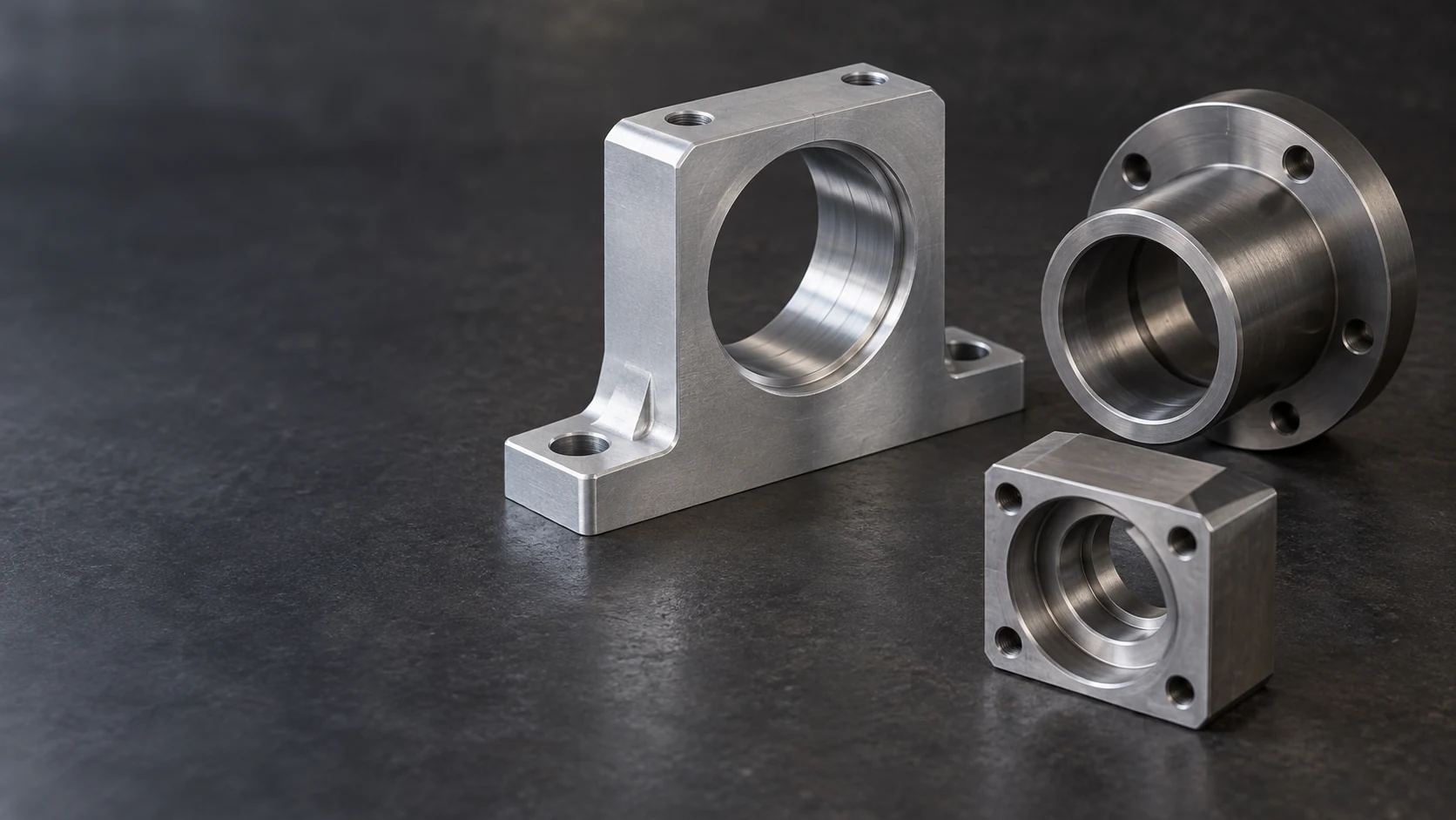
Machined housing, flanged sleeve and stepped-bore block with internal cylindrical seats

CNC Boring Services

We machine existing holes to the diameter, form and location specified for bearing seats, locating bores and mating sleeves. Our scope covers custom metal and plastic components, from a single housing to repeat batches.

  • Bearing seats & locating bores
  • Stepped, through & blind bores
  • Drawing-defined fits & inspection

Components with functional bores

We supply bored housings, sleeves and mounting components for equipment builders and part buyers. Each bore is considered with the surfaces that locate it in the assembly: its mounting base, end face, shoulder or neighboring bore.

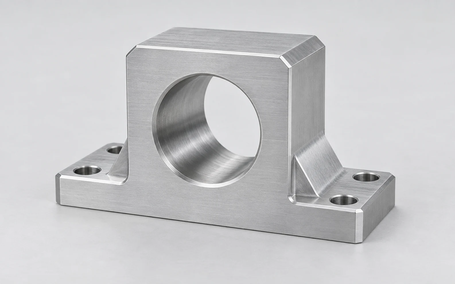
Machined aluminum bearing support with a central through-bore, reinforced base and mounting holes

Bearing housings

We finish the bearing seat in relation to the housing base and locating face. The drawing should distinguish the seat diameter from its axis position and shoulder requirements, so a correctly sized bore also sits in the right place.

  • Bearing seats
  • Mounting bases
  • Axis location
Discuss this housing
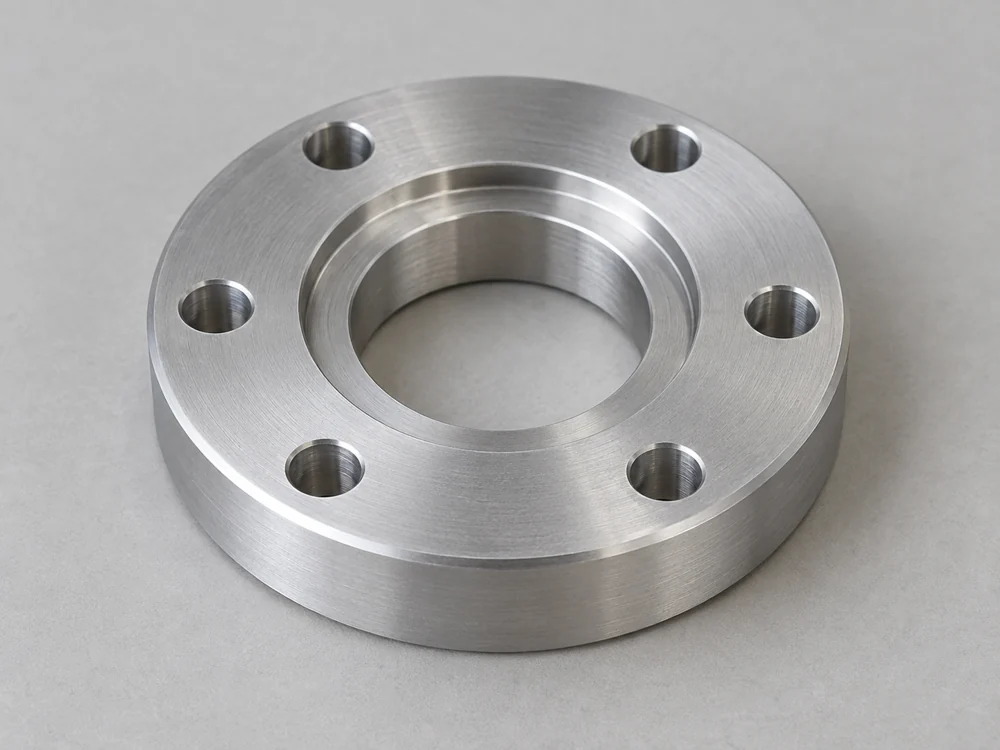
Round aluminum locating plate with a central stepped bore and six surrounding bolt holes

Locating-bore plates

We machine central locating bores in plates that connect a pilot, flange or equipment body to a bolt pattern. The locating diameter establishes the position; the surrounding fixing holes retain the assembly.

  • Central pilots
  • Bolt-circle relationships
  • Seating faces
Discuss this plate
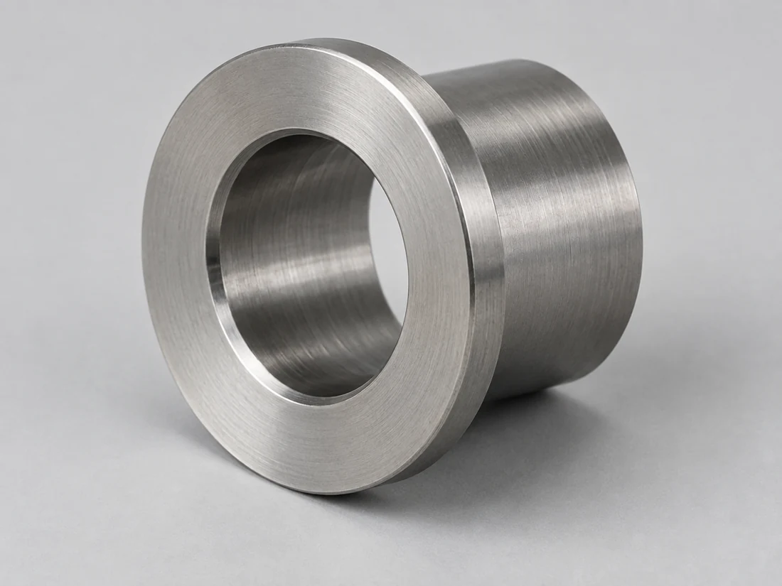
Machined steel flanged sleeve with a concentric through-bore and turned end face

Flanged sleeves

We make sleeves with a controlled internal diameter and a flange or shoulder for axial location. Bore size, wall section and the distance from the seating face to the end are separate drawing requirements.

  • Internal diameters
  • Flange faces
  • Axial lengths
Discuss this sleeve
Rectangular aluminum block with two bore diameters, an internal annular shoulder and four mounting holes

Stepped-bore blocks

We machine blocks with two or more internal diameters for stepped inserts or locating assemblies. The bore steps need a common axis where specified, while shoulder depth determines where each mating feature stops.

  • Coaxial steps
  • Shoulder depths
  • Insert seats
Discuss this block
Aluminum block with a circular blind seat, solid floor and four threaded mounting holes

Blind seating bores

We machine blind seats for components that stop inside a body. Full-diameter depth, bottom shape and corner clearance are defined separately; a drill point or internal radius must not prevent the mating part from seating.

  • Full-diameter depth
  • Bottom clearance
  • Seating shoulders
Discuss this blind bore
One-piece aluminum support with aligned bores through two parallel cheeks and two mounting holes in its base

Paired-bore supports

We review supports whose separated bores must locate a shared shaft or pin. The part drawing identifies the relationship between those bores and the mounting datums, with access through both walls considered in the setup.

  • Related bore axes
  • Separated walls
  • Mounting datums
Discuss this support

Boring scope and the starting hole

An existing hole may need substantial stock removal, a final sizing cut or correction relative to the part datums. We select the route from its current condition and the finished requirements. For large housings, our large-part CNC machining page addresses component support and access.

Rough bore preparation

We assess the starting diameter, interrupted surfaces and remaining stock before preparing the hole for finishing. Existing chatter or deep marks must be removed within the available allowance; a light sizing pass cannot simply conceal them.

Starting size · cleanup stock · entry face

Finish boring for fit seats

We plan the final cut around the specified bore limits, surface and material condition. The inspection requirement follows the function of the seat, including any form control that a diameter limit alone does not cover.

Size limits · bore form · surface finish

Related bores and datum features

We establish how each bore is located from the mounting or reference surfaces. Where axes must align across steps or separate walls, setup and measurement have to preserve that relationship rather than check each diameter in isolation.

Bore axes · shoulders · reference faces

Bore geometry that affects the machining route

We review the material around the finished bore and the path the tool needs to enter and leave it. These details determine whether an existing blank can reach the drawing without changing a functional surface.

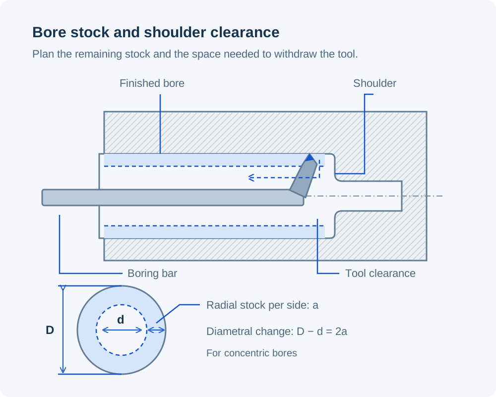
Section of a stepped bore with a boring bar and retraction path, plus concentric bore circles distinguishing radial stock per side from diametral change
For concentric holes, the increase in diameter is twice the radial stock removed per side.

Stock for size and axis correction

A larger finished hole needs material available around its entire circumference. Where the starting hole is off-centre, the cleanup allowance comes from its location relative to the required bore axis as well as its diameter. Where the body also needs pockets or faces, how CNC milling works explains those separate operations.

Depth and access to the opening

Bore depth starts at the entry face, but tool reach can also include a recess or an obstruction before that face. We review both distances, the entry condition and space for chip removal when assessing a blind or recessed bore.

Internal shoulders and reliefs

A sharp internal shoulder and a smooth cylindrical seat impose different tool-clearance requirements. We review the permitted corner radius, full-diameter depth and any relief so the mating part can contact its intended seat.

Wall support and release from the fixture

Thin sleeves and lightly supported housings can move under clamping. We distinguish dimensions required in the released component from those required in a defined assembled condition and plan support around that acceptance state.

Materials for bored housings and sleeves

A bore may change relative to its mating part as temperature, moisture or assembly forces change. We use the specified grade and stock condition to plan machining; the references below help compare those material effects.

Metal stock and dimensional response

Metal references for bored components
MaterialReference grade / stockProperty relevant to the bore
Aluminum6061 extrusionCLTE 23.6 µm/(m·K), 20–100°C
Stainless steel316L / EN 1.4404CLTE 16 µm/(m·K)
20–100°C
Alloy steel42CrMo4 +QT, Ovako 327A
Round bar, 40 < diameter < 100 mm
Hardness 270–320 HB
Brass / copperC36000 / C11000CLTE 20.5 / 16.9 µm/(m·K)
20–300°C / 20–100°C, respectively

References: Hydro Alloy 6061; Outokumpu Supra range; Ovako 42CrMo4; Copper Development Association C36000 and C11000. CLTE is the typical coefficient of linear thermal expansion over the stated interval; hardness applies to the stated bar condition and diameter.

Plastic stiffness and moisture response

Engineering-plastic references for bored components
MaterialReference stock gradeReference property
POM / acetalPOM-C, TECAFORM AH naturalTensile modulus 2,800 MPa
1 mm/min
NylonPA6, TECAMID 6 naturalWater absorption 0.30 / 0.60%
24 / 96 h, 23°C
PEEKUnfilled TECAPEEK naturalTensile modulus 4,200 MPa
1 mm/min

Typical values from Ensinger TECAFORM AH natural, TECAMID 6 natural and TECAPEEK natural product data. Modulus: ISO 527-2; water absorption: ISO 62. Stiffness affects bore support under load; moisture response matters when selecting the inspection and service condition.

We retain the specified grade and condition in the quotation. Material properties inform the fit design; they do not set the finished bore limits.

Bore surfaces and final treatment

We separate the cylindrical fit surface, the entry edge and the external appearance finish. Their requirements can differ even on a small sleeve or housing.

Bore finish and entry edges

We work to the roughness and edge conditions identified for the bore. A bearing lead-in, retaining shoulder and sealing surface need their own treatment; a general deburr instruction should not remove a functional edge.

External appearance surfaces

If a housing requires a cosmetic finish, we identify the bore and other fit surfaces that must be protected. Blasting a visible exterior and finishing an internal seat are separate operations with separate acceptance criteria.

Fits after coating or heat treatment

We establish whether bore limits apply before or after the specified treatment. Coating buildup and heat-treatment movement affect the sequence; masking or subsequent finishing must be included in the agreed route.

Diameter, bore form and datum relationships

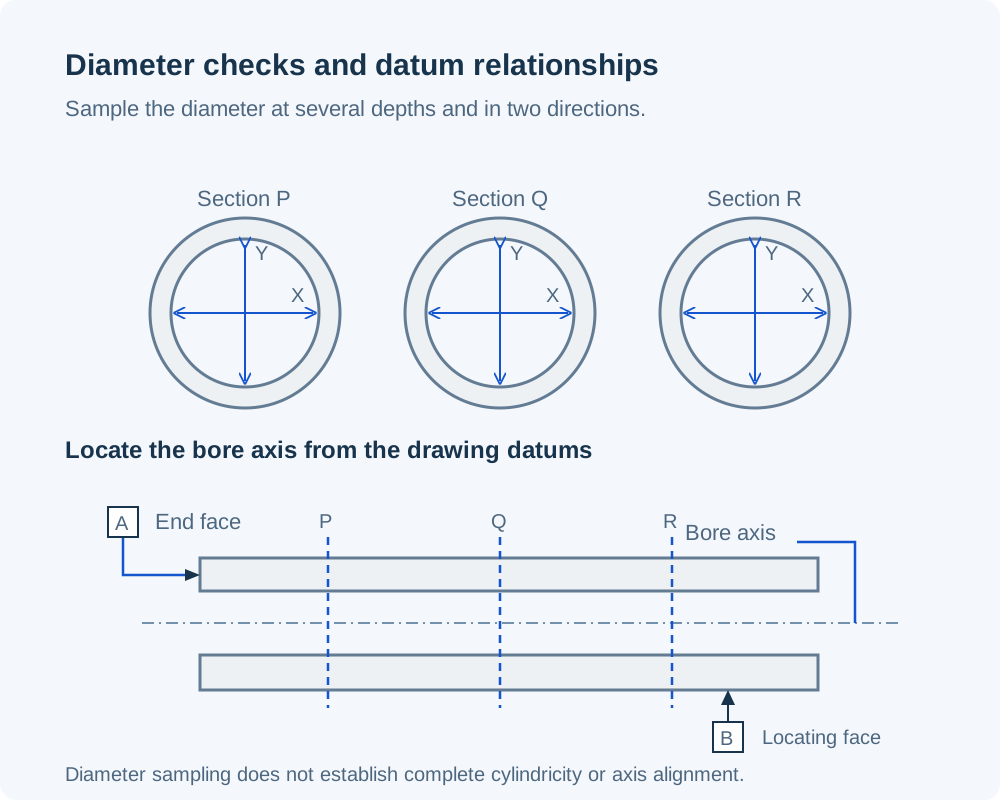
Three axial bore sections with two perpendicular diameter measurement directions at each section, above a separate side view locating the bore axis relative to an end face and a locating face

We check the requirement stated on the drawing. A bore within its diameter limits can still have an unacceptable form or be misplaced relative to a mounting face.

Readings at several depths and directions help reveal size variation. Those readings do not, by themselves, establish complete cylindricity or the relationship of the bore axis to the part datums.

The H7 values below are a reference for drawings that specify that hole class. We assess the particular size, material, access and inspection requirements before accepting the machining scope.

Finished-bore inspection requirements
FeatureRequirementVerification
Bore diameterSize at defined depths and directionsBore measurement or agreed gauges
Cylindrical formRoundness, taper or cylindricityMethod selected for the specified form control
Bore axisLocation and orientation to datumsDatum-based coordinate measurement
Internal shoulderDepth and seating-face orientationAxial and orientation checks
Bore surface and edgeRoughness and entry conditionSpecified roughness measurement; edge inspection

We agree the measurement method and any supplied dimensional record against these features. The required material condition, support or assembly state is included where it changes acceptance.

H7 bore limits by nominal diameter
Nominal diameter (mm)Lower deviation (mm)Upper deviation (mm)
>6–100+0.015
>10–180+0.018
>18–300+0.021
>30–500+0.025
>50–800+0.030

Each interval excludes its lower boundary and includes its upper boundary. These limits apply only where H7 is specified; form, position and finish remain separate requirements. Values: ELESA+GANTER, DIN ISO 286 reference tables. Standard: ISO 286-2

First parts, batches and repeat bore work

The incoming hole condition matters as well as the finished drawing. We distinguish a first fit evaluation from batches of prepared blanks that may vary in size or alignment.

First-part fit evaluation

We identify the seat that will be evaluated with the mating component and the dimensions that need an inspection record. An assembly trial can then reveal a fit issue without replacing the drawing-based checks.

Batches of prepared blanks

We review how much the starting bores vary across the batch. A route that cleans up one blank may leave marks or insufficient wall on another if the incoming hole size and position are uncontrolled.

Repeat components and matched interfaces

We keep the approved bore limits, reference surfaces and delivered treatment tied to the part revision. A change to the mating bearing, shaft or insert may require the fit to be reviewed even when the housing outline stays the same.

What affects a CNC boring quotation?

We quote the work needed to bring the starting component to its finished bore requirements. The same final diameter can involve very different preparation, access and verification. Programming and initial setup costs are shared across the ordered batch.

Starting hole and cleanup allowance

The existing diameter, location and surface condition determine how much preparation is needed before finishing. A cast or partly machined hole requires its own starting-condition review.

Tool reach and setup access

Recessed openings, deep shoulders and separated bore walls affect tool access and support. Additional setups can be needed to reach the hole while maintaining its relationship to the mounting datums.

Form and location requirements

A diameter limit, cylindricity requirement and bore-position tolerance require different evidence. We include the checks actually specified rather than treating every close fit as the same inspection task.

Final condition and protection

Treatments before or after boring, protected fit surfaces and the requested dimensional records contribute to the delivered cost. They are included in the scope alongside the cutting operations.

From starting component to finished bore

  1. Review the existing hole

    We compare the finished drawing with the current blank, including hole size, stock around the bore and usable reference surfaces.

  2. Agree the finished condition

    We define the bore limits, datum relationships, treatment sequence and acceptance state before fixing the machining scope.

  3. Machine and verify the features

    We follow the planned preparation and finishing route, then check the specified size, form and position requirements using the agreed methods.

  4. Protect the finished seats

    We protect entry edges and internal fit surfaces from damage in packing. Part identification and the agreed records remain traceable to the delivered components.

Questions about CNC boring orders

Does an H7 bore automatically provide a press fit for a bearing?

No. H7 defines the hole’s size limits, not its interference with a particular bearing. The result also depends on the bearing outside-diameter limits and the selected fit for the load and operating conditions. We use the fit specified for the assembly rather than treating every H7 bearing seat as a press fit.

Can boring make an oversized hole smaller?

No. Boring removes material. If a hole is already beyond its permitted maximum size, we need an approved change such as a redesigned interface or a separately engineered sleeve arrangement before considering further work. A new machining pass cannot restore missing material.

How should a split housing be specified for final bore acceptance?

The drawing should identify the mating housing halves, locating features and assembly condition used for acceptance. If the bore must meet its limits with the cap installed and tightened, we need that condition defined. The assembled bore is measured with the cap installed and tightened, when that is the acceptance condition.

Can an inch bore be replaced by the nearest metric H7 size?

A unit conversion can preserve the exact original limits; choosing a nearby metric nominal size changes them. We retain the original fit unless a revised metric bore and its mating component have been approved together. Adding H7 to a rounded diameter is not a direct conversion.

What if a keyway or cross-hole interrupts the bore?

We need the interruption shown on the drawing, including its position and size. It affects the cut and the available surfaces for diameter measurement. We identify continuous measurement lands and any required edge condition so a reading across an opening is not mistaken for the bore size.

What happens if finishing exposes porosity in a cast bore?

We distinguish exposed material voids from a machining-surface defect and refer them to the agreed casting acceptance criteria. Removing more material is only an option if sufficient allowance remains and the finished requirements can still be met. Any repair or part replacement needs a separate disposition; it is not assumed within boring.

Must the drawing require boring, or can it specify the finished hole?

If a contract or qualified process requires boring, state that process restriction. Otherwise, the drawing can specify the finished size, form, position and surface requirements, and we can review the complete hole-finishing route. This avoids prescribing a cutting method that does not suit the access or final surface.

PROJECT SUPPORT

Discuss your bored component

Send the finished drawing and tell us whether the starting part is solid stock, a casting or a partly machined component. We will review the bore requirements and the work needed to reach them.

VETCNCCNC MANUFACTURING
English
WhatsApp Email us

Tell us about your project

Share your requirements and we will get back to you by email.

PDF, CAD or ZIP · up to 20 MB