Spur gears
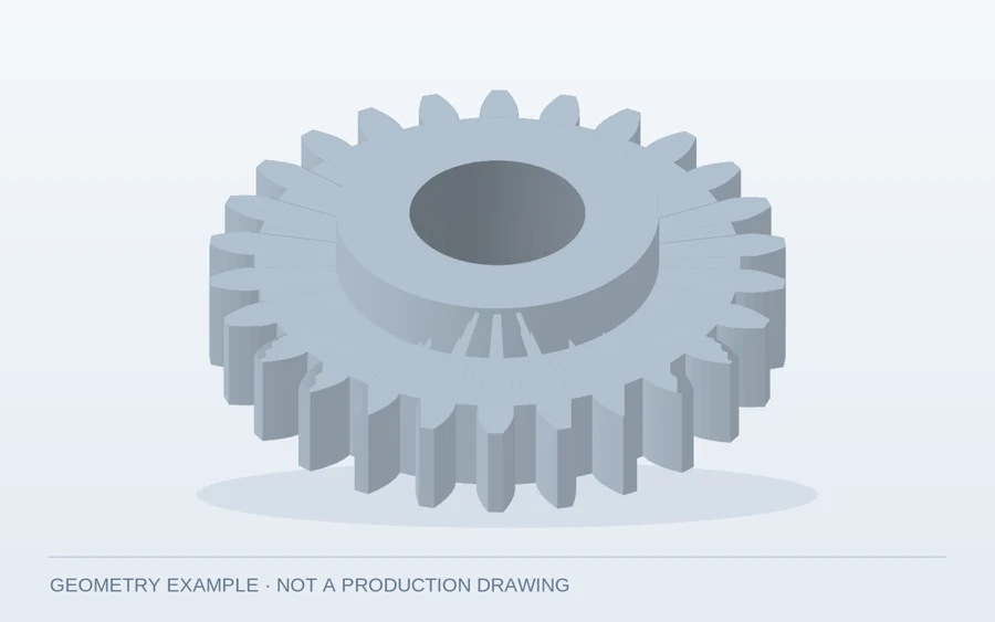
Straight teeth around a wheel or hub. Include the tooth count, module or diametral pitch, pressure angle and bore or shaft fit. Hub length and keyway location belong on the same drawing.
Discuss custom gears, pinion shafts and tooth cutting on supplied blanks with VETCNC. Each quotation defines the tooth-cutting route, finishing, inspection and manufacturing responsibilities for your drawing.
Straight teeth around a wheel or hub. Include the tooth count, module or diametral pitch, pressure angle and bore or shaft fit. Hub length and keyway location belong on the same drawing.
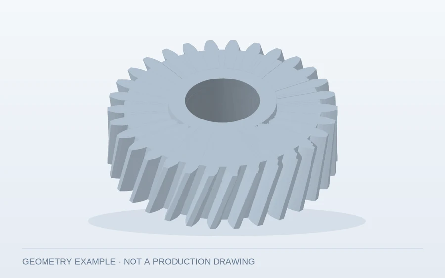
Angled teeth add a helix angle and hand to the specification. Identify whether the module or diametral pitch is normal or transverse, and include the mating gear information.
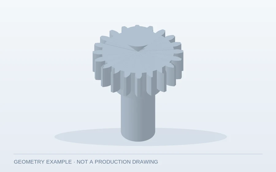
The teeth and shaft are part of one component. Mark the bearing journals and datum axis so the tooth inspection and shaft inspection refer to the intended mounting position.
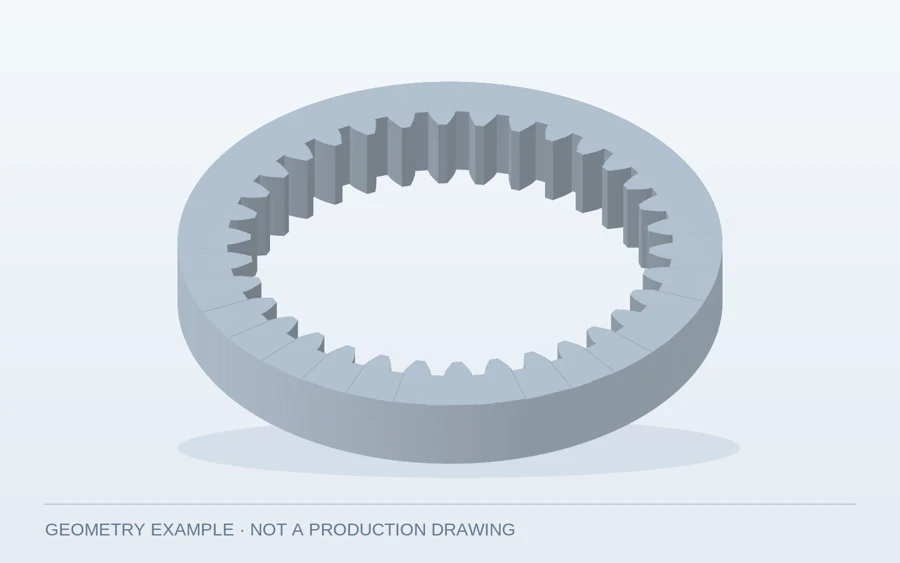
Teeth face inward around the ring. Add the tooth data, face width, wall section and locating features. Internal cutting-tool access needs checking alongside the finished geometry.
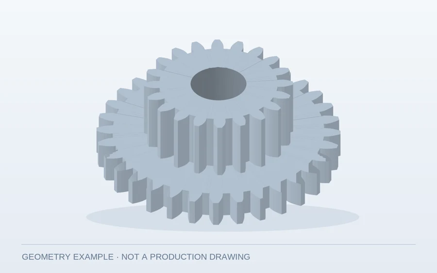
Two toothed sections share a hub or shaft. Specify each section separately and show their spacing. Where angular alignment matters, define that relationship rather than leaving it to the model.
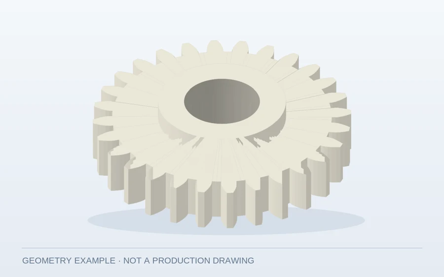
Name the exact polymer grade, any filler and any metal insert. Include the working temperature and mating material so fit, wear and dimensional behavior can be reviewed together.
No gear examples match this search.
Send your drawing to discuss custom gears, pinion shafts or tooth cutting on supplied blanks. Gear geometry, manufacturing route and inspection scope are confirmed for each order.
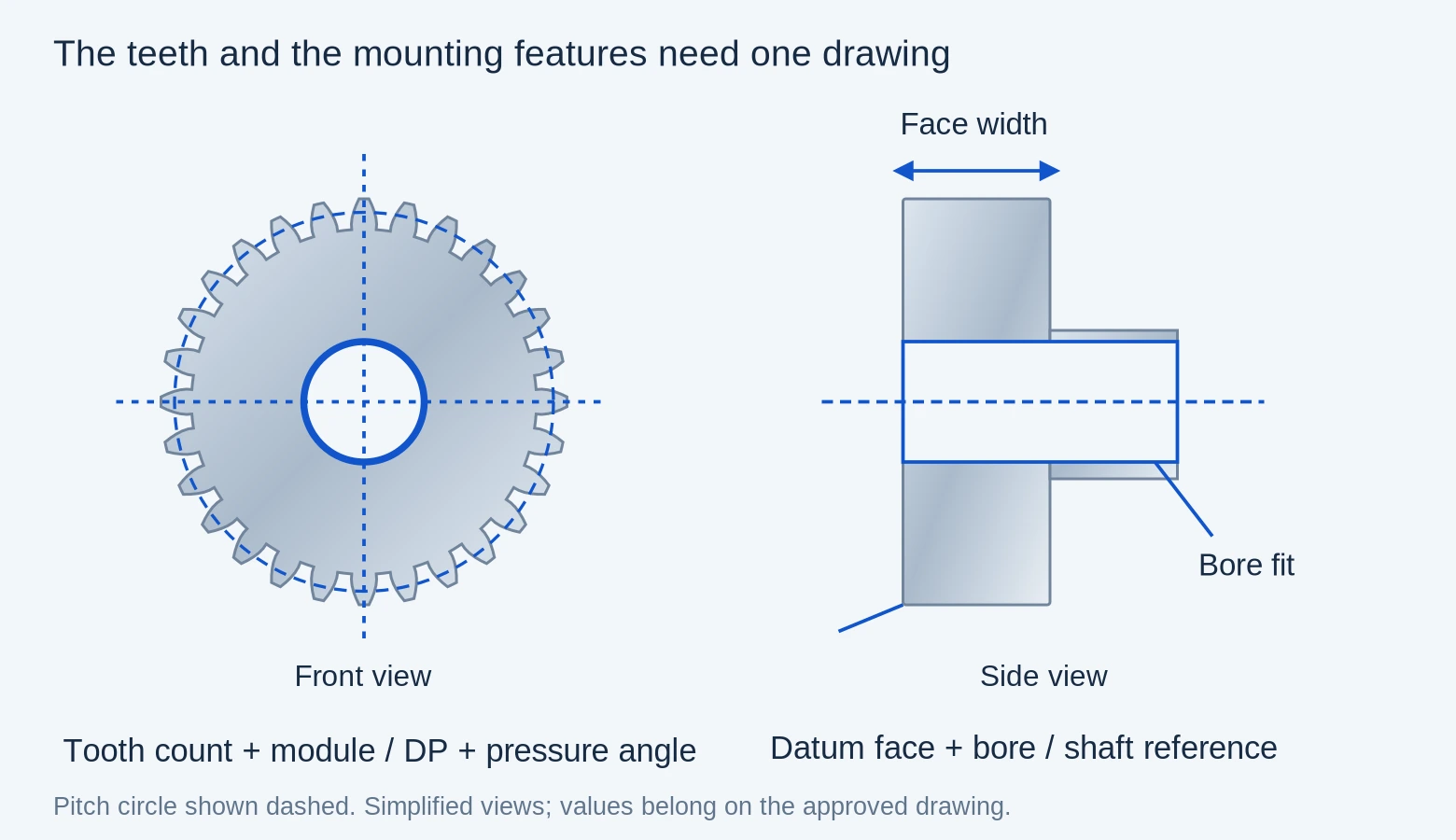
An outside diameter and a photograph do not fully define a gear. The drawing needs the tooth count, pitch system, pressure angle and any changes to the basic tooth form. For helical gears, add the helix angle and hand.
Module and diametral pitch are different ways of specifying tooth size. A helical-gear specification also needs to identify the normal or transverse system; a number without that context can describe a different tooth geometry. [1][2]
Show the bore or shaft fit, face width, hub dimensions, keys or other locating features. Identify the datum face and axis used to inspect the teeth. A gear can have the right tooth count and still fail to fit its shaft or align with its mate.
| Item | Specification | Purpose |
|---|---|---|
| Tooth geometry | Count; module/DP and reference plane; pressure/helix angles; hand | Define the tooth system |
| Profile and thickness | Profile shift, modifications, span or over-pins dimensions | Control tooth form and thickness |
| Mounting | Bore, journals, axis, width, hub, key, angular relationship | Locate the gear in the assembly |
| Mating gear | Mate ID, center distance, backlash, test conditions | Define the assembly check |
Turning, milling and grinding can prepare the blank and mounting features; producing the tooth form is a separate part of the job. The quoted route will identify the tooth-cutting process and any specialist partner involved.
External gears may use hobbing, profile milling or another suitable cutting process. Tooling, module, face width, access and order quantity determine whether a route can produce the specified tooth form.
Confirm the blank features, the datum used for cutting, and any shoulder clearance before tooth cutting begins. Spur and helical versions also need different geometry in the tool setup.
[3]Internal teeth may call for gear shaping, power skiving or another qualified method. The bore opening, face width, nearby shoulders and space beyond the teeth affect tool entry and exit. A tool that fits the opening may still have insufficient working clearance.
Supply a section view when the ring includes a flange or a blind recess. We can then discuss a route based on the entire part rather than only its internal tooth count.
[4]A hardened gear may need a gear-specific finishing operation to meet the specified tooth quality. Grinding the bore or shaft journals does not, by itself, finish the tooth flanks. State which surfaces need finishing and whether the gear is supplied before or after heat treatment.
Where tooth grinding is required, confirm the available process, stock allowance and inspection method before assigning it to the order. Keep tooth requirements separate from ordinary cylindrical or surface-grinding requirements.
[5]Give the material designation, delivery condition and final hardness requirement. Where case hardening is specified, include the applicable case-depth requirement and test method rather than writing only “hardened.”
Steel machining →For stainless steel, bronze or another specified alloy, send the exact grade and intended use. Do not substitute an easier-to-cut material on the basis of a similar appearance or nominal strength.
Compare material families →POM and nylon are material families, not complete gear specifications. Include the particular grade, reinforcement or lubricant, insert details and the conditions under which dimensions are to be inspected.
Engineering plastic machining →Machine the surfaces needed to locate and hold the part. Agree which bore, journal or face will remain the reference through later work.
Use the approved tooth definition and cutting route. Check the first pieces before repeating a setup across the batch.
Follow the agreed heat-treatment sequence and leave any planned finishing stock. Some orders use pre-hardened stock; others need treatment after tooth cutting.
Complete the specified tooth and mounting surfaces in the final condition. Match the part identification to the material, treatment and inspection records.
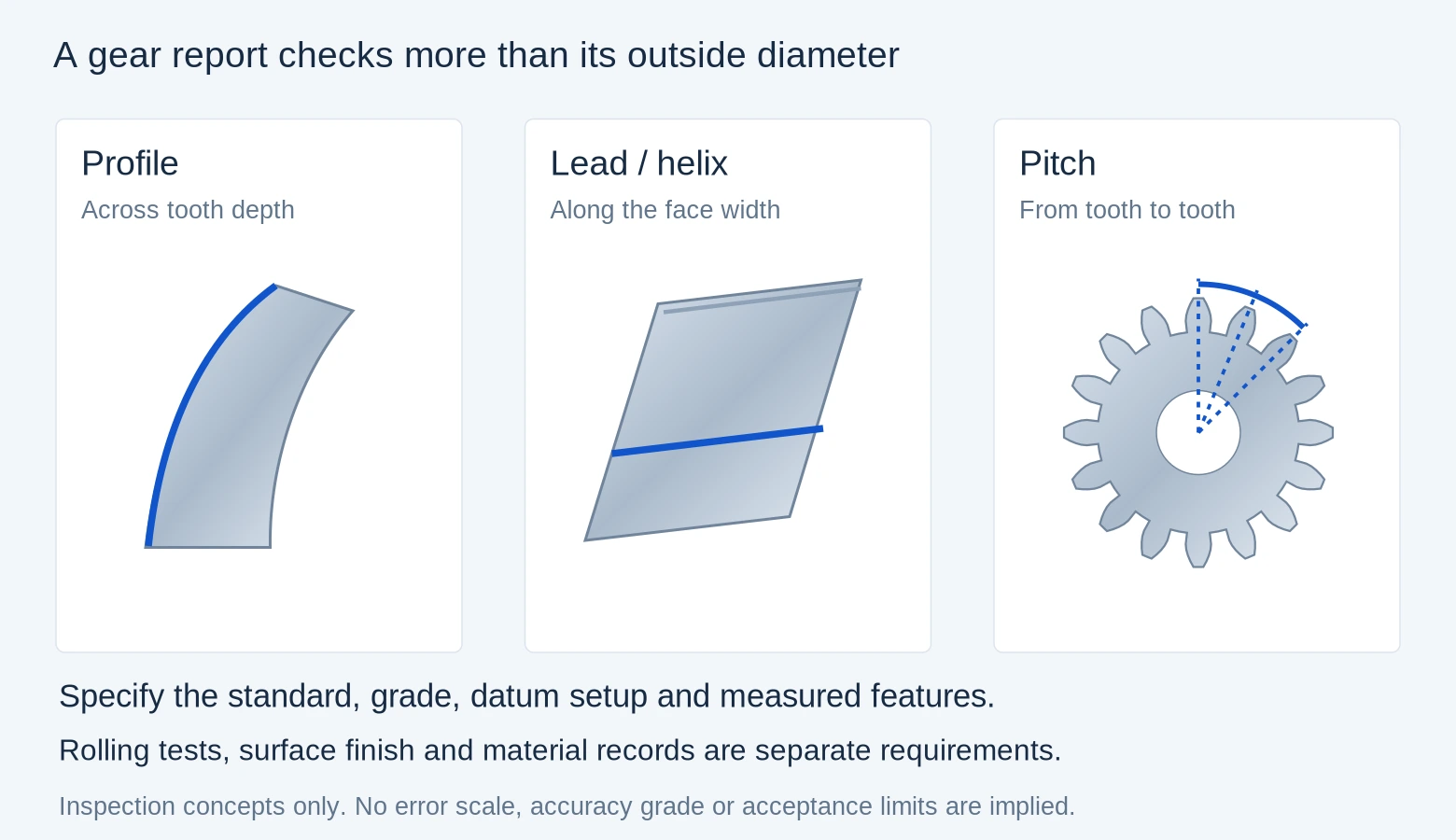
State the standard, revision and gear quality grade, together with the tooth measurements and mounting features to report. Confirm grade definitions against the specified standard rather than matching grade numbers across standards.
Gear metrology separates profile, lead or helix and pitch measurements. Bore size, journal fit, surface texture and hardness answer other questions; they should not be treated as substitutes for a tooth report. [6][7]
| Requirement | Scope | Records |
|---|---|---|
| Tooth geometry | Profile, lead, pitch, runout, datum axis | Specified gear inspection report |
| Tooth thickness | Span, over pins/balls, measurement conditions | Results using the specified method |
| Mounting features | Bore, journals, faces, key, alignment | Drawing-based measurement results |
| Material and treatment | Grade, condition, hardness, case depth | Material and treatment lot records |
| Mating or rolling test | Mate/master, distance, load, acceptance limits | Results for the specified test |
The inquiry covers the blank, teeth, specified treatment and final inspection. We will identify which operations are included, who performs them and what records accompany the parts.
Include the blank drawing, incoming dimensions, material condition and available stock. Mark finished surfaces that must be protected, plus the datums available for locating the teeth.
Kevin can coordinate a suitable manufacturing partner where the job needs a specialist process. The quotation should name the delivery responsibility and approval steps. A direct introduction is also possible; the factory, purchase order and inspection arrangement should be clear before any work starts.
Gear form, pitch system, face width and access drive the cutting method. Existing suitable tooling and a released tooth definition can change the preparation required.
Heat treatment, gear-specific finishing, mounting accuracy and the requested report scope affect the work after the teeth are first cut. Compare quotes in the same final condition.
State sample and production quantities separately, along with expected repeat orders and any tooling ownership or storage requirements.
We review custom gear work against your drawing and required final condition. Send the drawing and quantity so the manufacturing and inspection scope can be confirmed.
Start with tooth count, module or diametral pitch, pressure angle, gear type, face width, mounting dimensions, material and quantity. Add helix angle and hand for helical gears, plus the quality standard, any tooth modifications and the required inspection records.
Those two values help identify the part but do not fully define its teeth. Pitch system, pressure angle, possible profile changes and mounting details still need resolving. Send an existing drawing or ask for a separate specification-review step.
Turning or milling can prepare the blank and mounting features. The teeth may be produced by hobbing, shaping, power skiving, profile milling or another suitable process. The quotation identifies the operations needed for the specified tooth form and final condition.
Yes. Send the internal-gear section view or helical-gear data with the drawing. Tool access, tooling and inspection requirements are confirmed before the work is accepted.
Supply the outside diameter, face width, pitch data and required quality standard and grade. The machining and inspection range must be confirmed for your gear, based on the geometry, tooling and available equipment.
Include those operations in the request, with hardness, case depth where applicable, and final tooth requirements. The processing sequence, finishing allowance and available gear-finishing route need confirming. Bore grinding alone is not tooth grinding.
A sample can support an initial review, but wear can change tooth thickness, bore size and other features. Include the mating gear, old records and assembly details where available. Agree the replacement drawing and approval step before making a batch.
A one-off can be reviewed, but custom tooling and inspection preparation may dominate the cost. State the sample quantity and any later production quantity separately. Existing suitable tooling and the requested tooth form affect feasibility.
Specify the required material records, dimensional report and tooth measurements before ordering. Gear-profile or lead reports and assembly tests are not automatically included in a general dimensional report. The quote should list the deliverables and the responsible manufacturing or inspection site.
Send the gear drawing, tooth-data table, section view and mating reference where available. Include the required material, final condition and inspection records.
References for gear terminology, cutting processes and inspection. Use the approved drawing and specified standard for your order. Manufacturing and inspection responsibilities are confirmed during quotation.