On this page
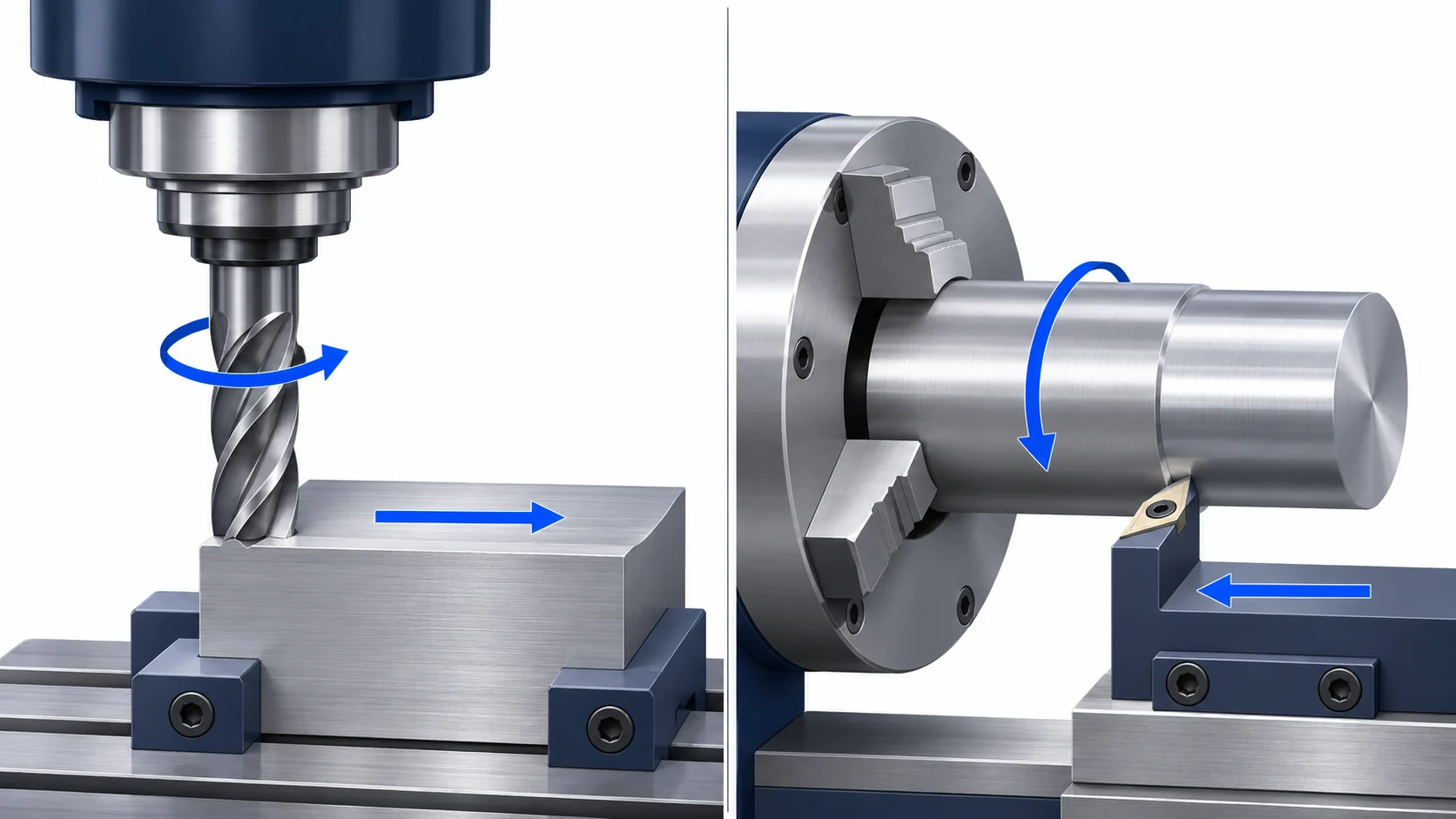
Cutting speed is the speed of the cutting edge relative to the material at the contact diameter. Feed rate describes how fast the tool advances, but the useful unit depends on the operation: millimeters per minute for table motion, millimeters per tooth for a milling edge, or millimeters per revolution for a turning tool. They are connected by spindle rpm; they are not two names for the same setting. Change a cutter or workpiece diameter while leaving rpm alone, and the cutting speed changes. Change rpm while leaving linear feed alone, and the amount each edge removes changes.
That distinction is useful when a tool is replaced, a part steps down to a smaller diameter, or a program appears faster but leaves a worse surface. This guide works through one milling cut and one turning cut, then shows which value to recalculate before changing a program. The numbers demonstrate the relationships, not cutting recommendations for an unspecified tool and material.
Name the speed and feed value before comparing settings
A machine display may show S = 5,000 and F = 1,200. Without the active units and feed mode, those numbers are incomplete. Spindle speed n is revolutions per minute (rpm). Cutting speed vc is the distance traveled by the engaged cutting edge along the circumference per minute, usually meters per minute (m/min) or surface feet per minute (SFM). Linear feed vf is the axis travel rate, usually millimeters per minute (mm/min) or inches per minute (IPM).
| Value | Metric unit | What it tells you |
|---|---|---|
| Spindle speed, n | rev/min (rpm) | How many rotations occur each minute |
| Cutting speed, vc | m/min | Surface travel at the engaged diameter |
| Milling feed per tooth, fz | mm/tooth | Nominal advance per effective cutting edge |
| Turning feed per revolution, fn | mm/rev | Tool advance for one workpiece revolution |
| Linear feed, vf | mm/min | Programmed or resulting axis travel rate |
The units in the table are part of the calculation, not interchangeable labels. A milling program at 0.06 mm/tooth does not move at 0.06 mm/min. It moves at a rate determined by rpm and the number of effective teeth cutting. Likewise, a turning feed of 0.18 mm/rev becomes a different mm/min travel as rpm changes. Sandvik Coromant’s milling and turning formula sheets use these separate symbols and units.
For a simple peripheral end mill, the nominal cutter diameter is usually the cutting diameter in the surface-speed calculation. A ball-nose or round-edge tool can engage at a smaller effective diameter at the actual depth of cut. Its surface speed cannot be inferred safely from the nominal outside diameter alone. That geometry is separate from the material-specific toolmaker speed and chip-load range. The spindle speed, torque and power guide covers whether a spindle can support a proposed cut; the arithmetic below explains what the proposed speed and feed mean.
Milling example: a larger cutter changes the rpm and table feed
Assume a 12 mm diameter, four-effective-tooth end mill runs at 5,000 rpm and 0.06 mm/tooth in a straight pass. For this example the engaged diameter equals 12 mm. Sandvik’s metric relationships are vc = π × D × n ÷ 1,000 and vf = fz × n × zeff. With D in millimeters, vc is in m/min; with fz in mm/tooth, vf is in mm/min.
The cutting speed is π × 12 × 5,000 ÷ 1,000 = 188.5 m/min. The table feed is 0.06 × 5,000 × 4 = 1,200 mm/min. Neither number alone establishes a suitable cut. Tool grade, material and condition, axial and radial engagement, reach, chip evacuation and machine limits still determine whether the toolmaker’s applicable range is met. The milling process guide explains the operations in which those inputs are used.
Now replace the tool with a 16 mm cutter that also has four effective teeth. If the intent is to keep both 188.5 m/min cutting speed and 0.06 mm/tooth nominal feed, rpm must fall to 188.5 × 1,000 ÷ (π × 16) = 3,750 rpm. Linear feed then becomes 0.06 × 3,750 × 4 = 900 mm/min. Keeping the old 5,000 rpm and 1,200 mm/min instead would preserve 0.06 mm/tooth but raise surface speed to π × 16 × 5,000 ÷ 1,000 = 251.3 m/min.
| 12 → 16 mm cutter change | RPM | Cutting speed | Table feed | Feed per tooth |
|---|---|---|---|---|
| Original 12 mm cutter, four effective teeth | 5,000 | 188.5 m/min | 1,200 mm/min | 0.06 mm/tooth |
| 16 mm; keep rpm and table feed | 5,000 | 251.3 m/min | 1,200 mm/min | 0.06 mm/tooth |
| 16 mm; keep cutting speed and feed per tooth | 3,750 | 188.5 m/min | 900 mm/min | 0.06 mm/tooth |
| 16 mm; keep cutting speed and table feed | 3,750 | 188.5 m/min | 1,200 mm/min | 0.08 mm/tooth |
The final row follows from 1,200 ÷ (3,750 × 4) = 0.08 mm/tooth. It is a one-third increase in nominal advance per edge. A programmer who updates rpm to preserve surface speed but forgets feed has changed the cutting load without explicitly choosing to do so. Conversely, slowing both rpm and table feed in proportion preserves the nominal feed per tooth but lengthens the cutting move: for an assumed 100 mm straight feed move, 100 ÷ 1,200 min is 5.0 seconds, whereas 100 ÷ 900 min is 6.7 seconds. These are feed-move times only; approach, exit, acceleration, other passes and tool changes are outside the calculation.
Tooth count is another independent variable. Suppose the 16 mm tool has three effective teeth, with 3,750 rpm and 0.06 mm/tooth unchanged. Its calculated table feed is 0.06 × 3,750 × 3 = 675 mm/min. If the program instead retains 900 mm/min, each effective tooth advances 900 ÷ (3,750 × 3) = 0.08 mm/tooth. Count the edges actually involved in the application rather than assuming every visible flute has the same effective engagement. A flute-count decision also affects chip space and stiffness; it cannot be made from the feed equation alone.
Why nominal feed per tooth is not actual chip thickness
Feed per tooth is an advance value, while maximum chip thickness depends on the part of the tooth arc that cuts. In peripheral milling at less than half the cutter diameter of radial engagement, the engaged tooth may never reach a position where its instantaneous chip thickness equals the nominal fz. Entering angles below 90 degrees and round inserts at shallow depths can thin the chip for different geometric reasons. Sandvik Coromant’s chip-thickness guidance separates these cases; applying a single compensation factor to every toolpath would be wrong.
For a simple straight-edge, 90-degree-entering-angle side-milling geometry, a radial engagement ratio r = ae/D below 0.5 gives a geometric maximum of approximately hmax = fz × 2√[r(1 − r)]. At 10% engagement and 0.06 mm/tooth nominal advance, that is 0.06 × 2√(0.1 × 0.9) = 0.036 mm maximum chip thickness. The calculation is a geometry illustration, not a direction to raise feed to any particular value: actual tool data, material, cutting depth, runout, machine rigidity and the desired surface must be considered. When the toolmaker provides engagement-specific data, use that range rather than transplanting a full-width slot value into a light side cut.
A chip that is too thin for the edge and material can rub rather than cut cleanly, generate heat and poor chips, and shorten tool life. An excessive chip can overload an edge, deflect a slender cutter or break it. Therefore “reduce feed” is not a safe universal response to noise or wear. First check the actual radial engagement and edge geometry, then compare observed chips, load and finish with the toolmaker’s application limits. If the path shifts between a light side cut and a near-full-width slot, the same programmed fz does not imply the same maximum chip thickness or cutting load.
Turning example: constant rpm and constant surface speed diverge
On a conventional lathe, the workpiece rotates and a stationary tool advances. For turning, use the machined workpiece diameter in vc = π × Dm × n ÷ 1,000. Linear advance is vf = fn × n, with fn in mm/rev. Sandvik’s turning formulas also give the engaged time for a constant-rpm axial pass as length ÷ (fn × n). That is one pass, not a full part cycle. The CNC turning page shows the rotational part features for which this distinction matters.
Assume a 40 mm turned diameter, 150 m/min target surface speed and 0.18 mm/rev feed. The calculated rpm is 150 × 1,000 ÷ (π × 40) = 1,194 rpm after rounding. Linear feed is approximately 0.18 × 1,193.7 = 215 mm/min. At that constant diameter, an assumed 60 mm axial cutting length takes 60 ÷ 214.9 = 0.279 min, or 16.8 seconds of engaged feed time.
Now consider a separate 20 mm diameter cut. If rpm remains at 1,193.7, surface speed falls to 75 m/min; with feed still set to 0.18 mm/rev, linear travel remains about 215 mm/min. If the control instead holds 150 m/min constant surface speed, rpm rises to approximately 2,387 rpm, and the same 0.18 mm/rev becomes about 430 mm/min. An otherwise identical 60 mm axial pass would then take about 8.4 seconds of engaged feed time. Those time figures compare two distinct constant-diameter passes; they are not a shortcut for estimating a facing cut while diameter changes continuously.
In an actual program, a spindle-speed ceiling can stop the commanded surface speed from being maintained at small diameters. If the assumed control limit is 1,800 rpm, the 20 mm cut is capped at π × 20 × 1,800 ÷ 1,000 = 113.1 m/min, and 0.18 mm/rev becomes 324 mm/min. The part does not receive 150 m/min merely because that number was programmed. Haas Automation’s lathe manual describes constant surface speed (G96), fixed rpm (G97), a G50 rpm ceiling, and feed-per-revolution mode (G99) for its control. Other controls and machines may use different codes or defaults; verify the actual program and controller before interpreting an F word.
Diagnose a poor cut by isolating the changed variable
When a previously acceptable process produces heat, short tool life, chatter or a different finish after a program change, compare the old and new cuts at the engaged diameter. The same rpm on a larger mill raises surface speed. The same rpm on a smaller turned diameter lowers it. A surface-speed difference can change wear or built-up edge behavior even when the displayed feed number is unchanged. The tool and material have to be considered before blaming feed alone.
Then calculate the actual advance per edge or revolution from the active mode. On a mill in mm/min feed mode, fz = vf ÷ (n × zeff). A lower rpm with unchanged mm/min feed raises fz. A cutter with fewer effective teeth does the same. On a lathe in mm/rev feed mode, the programmed fn stays constant while linear travel changes with rpm; in mm/min mode, a varying rpm changes mm/rev instead. A program that reads the same on screen can therefore generate a different cut when a mode, tool or diameter changes.
Use a short investigation in this order, because each step determines the meaning of the next:
- Identify the active units and feed mode. Read the actual controller state and toolpath; establish whether F is per minute or per revolution. Record programmed rpm or surface speed and any spindle cap.
- Use the engaged diameter and effective edges. For a mill, note the cutting diameter at the actual depth and the effective tooth count. For turning, note the diameter of each pass. Recompute vc, fz or fn, and vf with units shown.
- Check engagement and the physical evidence. Compare radial and axial depth, tool reach, chip form, machine load, sound, finish and wear. A light side cut and a full-width slot are not equivalent at the same nominal feed per tooth.
- Change the justified variable and verify the result. Select the applicable toolmaker data for the material and operation, then make a controlled trial. Measure the surface and dimensions that matter, and record the program, tool and workholding used.
This sequence prevents a common false diagnosis: a move takes longer after rpm is reduced, so feed is raised to recover time, but its per-tooth load was already higher. It also prevents the opposite error of reducing feed when low chip thickness is the cause of rubbing. Chatter has several possible causes, including tool overhang, workholding and engagement; changing a speed or feed can alter the symptom without identifying the underlying source.
Read cycle-time gains alongside cutting load and part quality
The feed-move calculations above make a faster program easy to imagine, but a shorter feed move does not guarantee a shorter accepted-part cycle. A higher table feed may require the machine to accelerate through short segments and still spend time entering, retracting and changing tools. A more aggressive chip load may reduce tool life or cause a finish that needs another pass. Conversely, a modestly slower feed may improve an edge’s survival enough to reduce interruptions. The balance depends on the tool, material, setup and what the finished part must meet.
Use feed-move time as one line in the process plan. For the 100 mm milling move, a reduction from 1,200 to 900 mm/min adds about 1.7 seconds to the straight cutting segment. If the full operation includes several approach moves, a tool change and inspection, that difference is less than the full cycle difference. In turning, the 16.8 versus 8.4 seconds shown for two 60 mm constant-diameter cuts assumes an uncapped spindle and identical geometry; a 1,800 rpm cap changes the second cut to 60 ÷ 324 = 11.1 seconds. No one of those values tells you whether the cut is stable or what a supplier should charge.
For design or process comparison, record the tool and work material, effective diameter, active speed/feed modes, radial and axial engagement, cut length, spindle limit, and observed quality. Then you can tell whether a different toolpath is faster because it removes material more efficiently, because it loads each edge harder, or because it silently changes the finish requirement. That is the practical use of separating cutting speed from feed rate.
Cutting speed and feed rate questions
Does increasing rpm always increase feed rate?
No. It increases cutting speed at a fixed diameter. Linear feed rises with rpm only when the same feed per tooth on a mill or feed per revolution on a lathe is maintained. If mm/min feed stays fixed, each milling tooth or turning revolution instead receives less advance.
What changes when I use a larger end mill at the same rpm?
Surface speed rises in proportion to the engaged diameter. With the same effective tooth count and the same mm/min table feed, nominal mm/tooth stays the same; to retain the original surface speed, lower rpm and then recalculate table feed if mm/tooth is also to remain unchanged.
Why does a lathe show higher rpm as the tool moves inward?
In constant surface speed mode, rpm increases as cutting diameter decreases so the edge can maintain the selected surface speed. A maximum-rpm clamp stops that increase when the limit is reached. In fixed-rpm mode, rpm does not follow diameter and surface speed falls as the diameter gets smaller.
Is feed per tooth the same as maximum chip thickness?
No. Feed per tooth is nominal advance per effective edge. Maximum chip thickness also depends on radial engagement and entering-angle geometry; a light peripheral cut can produce a thinner maximum chip than a near-full-width cut at the same nominal feed. Use application-specific tool data when adjusting either one.
Technical sources
- Sandvik Coromant, Milling formulas and definitions. Defines metric surface speed, spindle speed, table feed, feed per tooth, effective teeth and engaged cutting diameter.
- Sandvik Coromant, Turning formulas and definitions. Defines metric turning surface speed, feed per revolution and one-pass engaged machining time.
- Sandvik Coromant, Entering angle and chip thickness in milling. Explains chip-thinning conditions, low/high maximum chip-thickness consequences and peripheral engagement factors.
- Haas Automation, Lathe Operator’s Manual — NGC, 2024 edition, G96/G97/G50/G98/G99 sections. Describes constant surface speed, fixed rpm, rpm limiting and feed-unit modes on the Haas control.