On this page
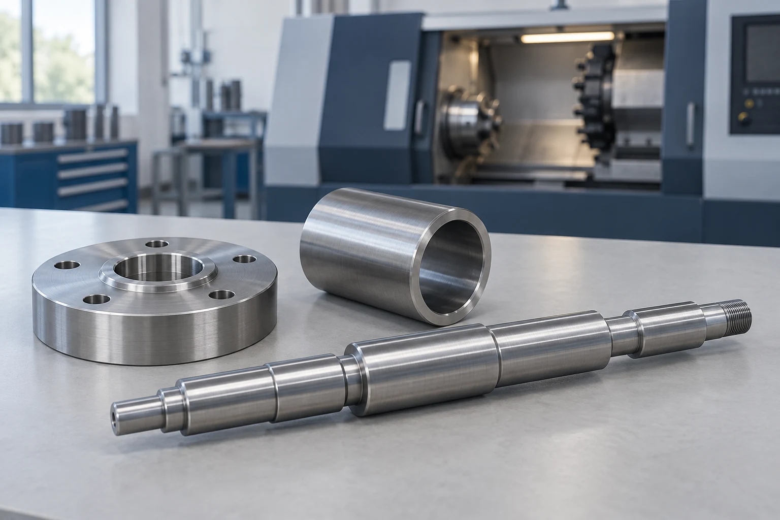
A CNC lathe specification sheet describes several different limits: what can pass through the spindle, what can rotate in the work area, and what the tools can reach. Start with the blank and the loading method, then check cutting diameter, working length and secondary features. A part that clears one limit can still fail another.
Swing and turning diameter describe different spaces
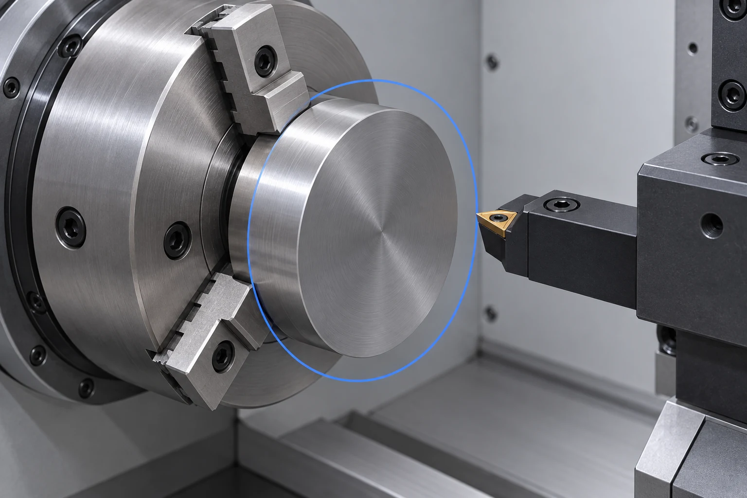
Swing describes rotational clearance at a stated location, such as over the bed or over the cross slide. Maximum turning diameter describes the cutting envelope with the manufacturer’s specified tooling arrangement. It can be smaller than the swing. A disk may rotate without hitting the bed while leaving too little room for the toolholder to reach its rim.
The numbers below come from Hurco’s TM6 product specification page, checked September 27, 2026. They illustrate how to read one model’s table; they are not VETCNC machine capacities.
| TM6 specification | Published metric value | What it helps you check |
|---|---|---|
| Swing over bed | 405 mm | Clearance over the bed |
| Swing over cross slide | 240 mm | Clearance where the cross slide is underneath |
| Maximum turning diameter | 316 mm | Specified cutting envelope |
| Maximum bar capacity | 45 mm | Through-bar loading limit |
| Maximum turning length | 340 mm | Specified axial machining range |
| Z-axis travel | 356 mm | Axis stroke |
| Distance between centers | 402.5 mm | Specified center-to-center spacing |
These limits apply at different locations and configurations. Do not combine the largest diameter and longest distance into an approved cylindrical work envelope. A complete setup includes the blank, rotating jaws, turret and every tool used for the planned turning operations. Hurco’s lathe terminology guide also notes that extended tooling can reduce the usable cutting envelope. [1]
Bar capacity is not chuck size
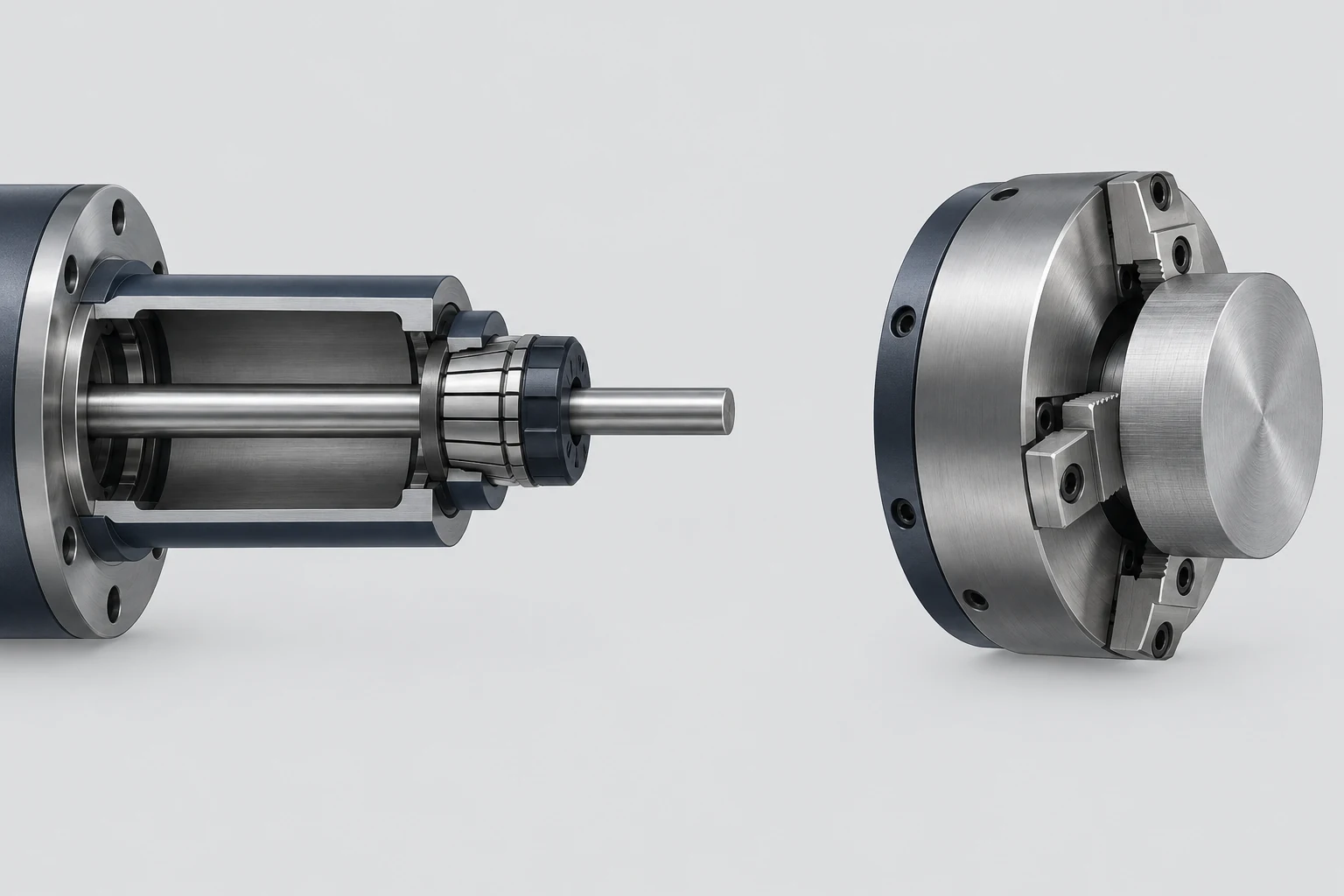
For a bar-fed part, compare the incoming stock diameter with the usable through-bar capacity. A finished 40 mm diameter does not help if the selected stock is too large to feed through the installed system. The route includes the spindle, drawtube, workholding and any liner or bar feeder; the bare spindle bore alone does not establish the complete passage.
Chuck diameter describes the chuck body, not a universal maximum workpiece diameter. Jaw type, mounting position, gripping range and allowed speed determine which blanks it can hold. Royal Products’ CNC collet-chuck documentation treats spindle mounting and the drawtube connection as machine-specific interfaces. [2]
A short blank larger than the bar capacity may instead be loaded from the front. That changes the question to jaw engagement, rotation clearance and cutting access. It does not make the blank acceptable automatically, and it changes material handling and the production route.
Turning length, Z travel and center spacing are not interchangeable
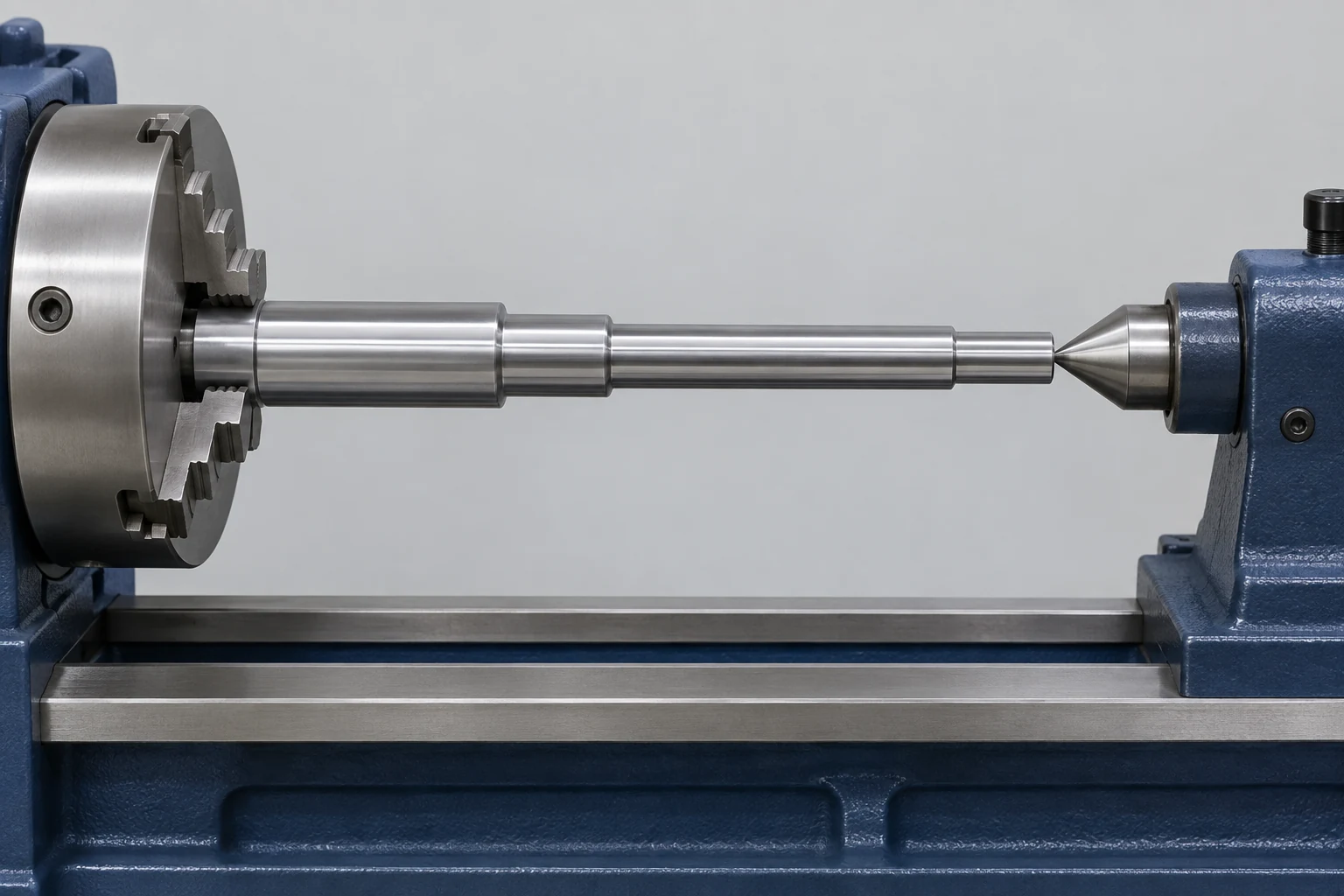
Z travel is the axis’s available stroke. Maximum turning length is the manufacturer’s stated machining length under its specified arrangement. Distance between centers is a separate spacing dimension for the stated center arrangement. The TM6 table lists three different values for good reason.
Sketch the installed chuck face, grip length, exposed stock, tool approach and tailstock position on the same axial layout. Deep jaws and projecting holders can consume working space. A center-supported end may also need a later operation to finish the center hole or an inaccessible face. There is no universal subtraction from Z travel that resolves every setup.
Once the shaft fits, evaluate its unsupported span and cutting loads. The article on why slender shafts deflect explains the support and stiffness problem that a length specification cannot answer.
Read speed, power and extra axes against the features
Maximum spindle speed is a ceiling, not a cutting-speed recommendation. Large diameters reach a given surface speed at fewer revolutions than small diameters. Check the torque available at the intended rpm and distinguish continuous output from a time-limited rating. Hurco’s TM-series linecard, for example, labels 30-minute and continuous spindle ratings separately. Do not transplant those ratings between model revisions. [1]
Extra axes answer feature questions:
- Live tooling rotates a cutter for suitable drilling or milling operations.
- C-axis control positions the workpiece angularly and, when supported, coordinates that rotation with linear motion.
- A Y axis adds linear motion away from the spindle centerline. It is not mandatory for every flat or offset feature: some paths use X–C interpolation.
- A subspindle can receive the part for work on the other end, provided a suitable transfer grip and tool access exist.
Haas documents C-axis interpolation and part transfer in its Lathe Operator’s Manual. These are configuration-dependent functions, not features of every CNC lathe. [3] If secondary features will move to a milling machine, evaluate that setup using the separate VMC specification guide.
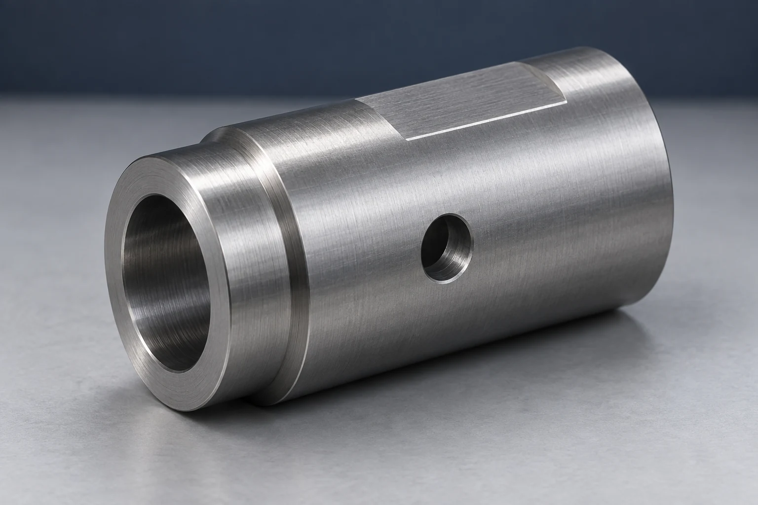
Screen three blanks without overreading the table
Use the TM6 values above for this hypothetical screening exercise. The blank dimensions are teaching assumptions, not completed customer parts. Each result identifies either a clear mismatch or the next setup question.
| Assumed blank and route | Initial result | Next decision |
|---|---|---|
| 50 mm round bar, through-bar feeding | Exceeds the listed 45 mm bar capacity | Choose another feed-capable configuration or evaluate cut blanks loaded from the front |
| 300 mm diameter × 30 mm disk, front loaded | Below 316 mm turning diameter; above 240 mm cross-slide swing | Check where the disk sits relative to the cross slide, plus jaw projection and the complete tool path |
| 25 mm diameter × 320 mm shaft blank | Nominal dimensions alone do not rule it out | Lay out grip and support space; verify cutting reach and shaft stiffness |
The disk shows why taking the smallest listed diameter is also misleading: the cross-slide limit matters where that structure and the rotating part occupy the same axial region. An envelope drawing or setup model must settle that relationship.
For a specific part, mark the loading route, grip surfaces, required cuts and unresolved clearance on the drawing. Bring that information to VETCNC’s CNC turning service review so the discussion starts with an actual manufacturing route.
FAQ
Can a lathe turn a part as large as its swing?
Only if the cutting envelope and complete setup also allow it. Swing addresses rotational clearance at a stated location. Toolholders, jaws and turret motion can impose a smaller usable diameter.
Does bar capacity limit the finished part diameter?
It limits the through-bar route. A wider short blank may be front loaded into suitable workholding. That route still needs an independent grip, clearance and cutting review.
Does a 12-station turret mean 12 live tools?
No. Station count describes tool positions; it does not establish whether those positions support driven tooling. Check the turret type, live-tool provision and holders in the installed configuration.
Can machine positioning accuracy be used as a part tolerance?
No. Positioning accuracy is a machine performance characteristic under stated test conditions. Finished dimensions also depend on the setup, workpiece, tools, thermal behavior and measurement method. The drawing still needs its own tolerances and acceptance plan.
Technical sources
- Hurco, TM6 product specifications, Buying a CNC Lathe? Here’s What to Know and Consider, and TM Series linecard C000-B-T497. Numerical screening values use the TM6 web table checked September 27, 2026; the linecard’s TM6i ratings are not substituted for TM6 values.
- Royal Products, Royal CNC Collet Chucks: spindle mounting, drawtube connection and workholding geometry.
- Haas Automation, Lathe Operator’s Manual, chapter 13, sections 13.2 C-Axis and 13.3 Dual Spindle. Machine-specific commands and ratings are outside this article’s scope.



