Skip to content
VETCNCCNC MANUFACTURING
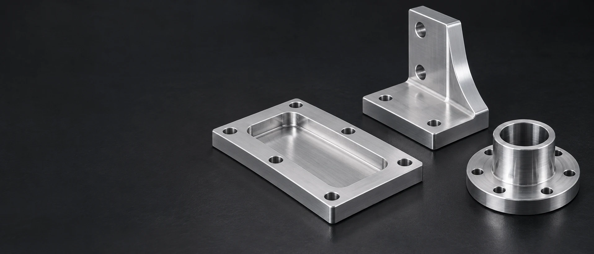
Silver pocketed mounting plate, L bracket and flanged hub on a dark background

7022 Aluminum
CNC Machining

See 7022 Plate References

7022 Tooling Plates, Retainers and Support Components

6 component types

Mold backing plates

We machine backing faces, fastening holes and local clearances in a rolled-plate blank. The retained face supports the adjoining tool, while recesses provide space for its attachments without interrupting the intended contact area.
Punch and tool retainers

A retainer holds the selected tool through its bore, shoulder and fastening features. We machine those interfaces together so the tool’s locating surface remains related to the retainer’s mounting face.

Rotary-table adapters

An adapter connects the table register and bolt pattern to the fixture above it. Turning or circular milling produces the locating features; the attachment holes and reliefs complete the two-sided connection.

Pallet and fixture blocks

A fixture block places its locating bores, stop faces and mounting holes within one body. We leave access for the intended clamps while preserving the lands that seat on the machine or pallet.

Circular mounting discs

A disc can carry a central opening, multiple mounting patterns or an annular seating face. Its useful section follows the connected components rather than treating every face as the same contact surface.

Guided-slide carriers

A carrier combines guide attachment faces with a mounting pattern and clearance for the moving assembly. We machine the specified support heights and shoulder positions within the body’s retained section.

Our 7022 component service covers milling, turning and associated feature work to the released part drawing. EN AW-7022 / AlZn5Mg3Cu is a heat-treatable wrought alloy. The selected rolled product and condition remain identified through manufacture; cast 7021 tooling plate is a separate material route.

Rolled 7022 Stock, T651 Condition and Plate Section

T651 rolled plate

A stress-relieved rolled plate provides a broad starting section for backing plates and tooling bodies. The agreed stock condition remains part of the machining route and delivered material definition.[1]

Selection focus
Original plate section and ordered temper

A named producer product

CERTAL and Alu50 describe particular commercial products based on 7022. Their published processing, supply and property details belong to those products. A named-product requirement stays explicit instead of being shortened to an alloy number.[2]

Selection focus
Approved producer and product definition

Blank direction and usable envelope

A cut blank retains the original plate orientation and section. The route places bores, shoulders and loaded attachments within that envelope, allowing enough material for the final working surfaces.

Selection focus
Plate orientation and retained features

Plate, disc or another specified form

A circular plate cutting can reduce removal for a rotary adapter; rectangular plate can suit a fixture body. Bar or extruded stock is considered only with its own product specification and property basis.

Selection focus
Product-form suitability for the part
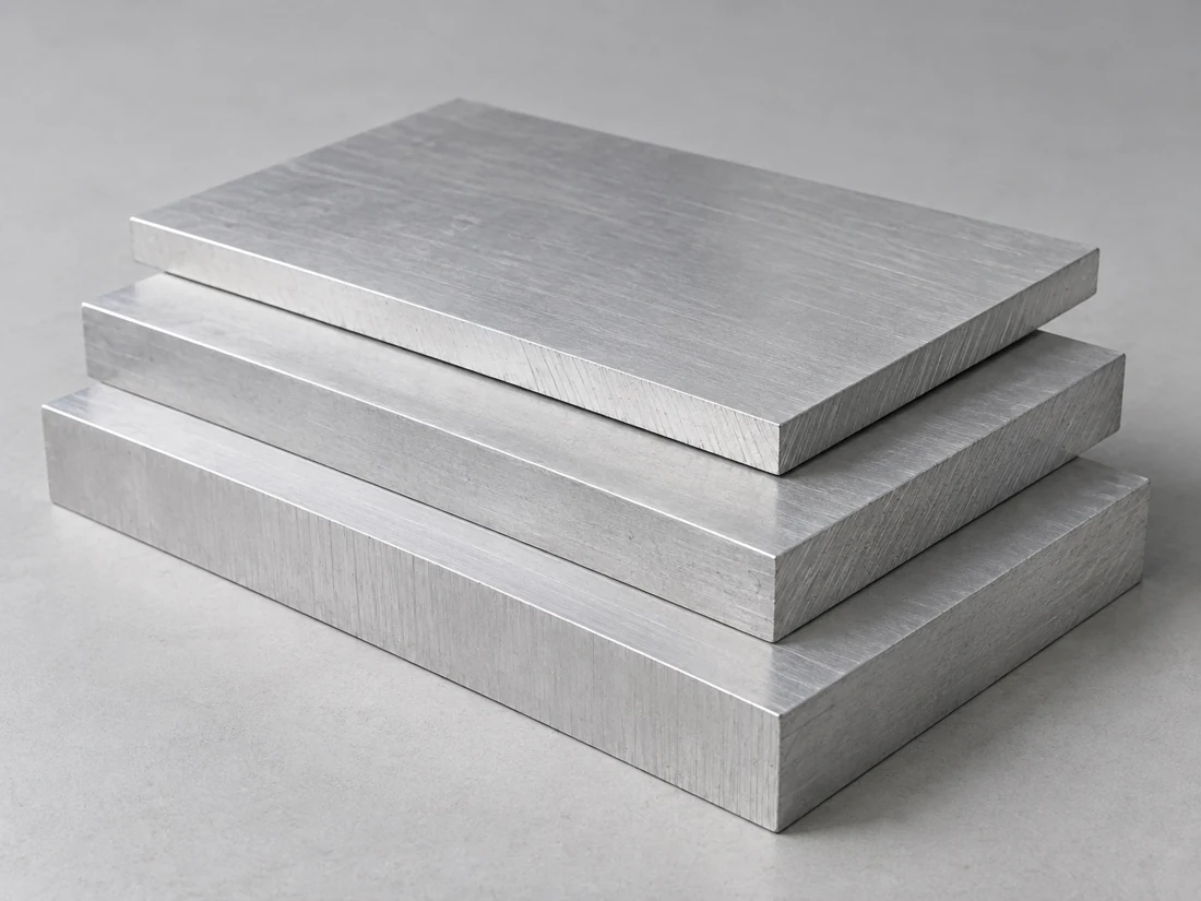
Stacked rectangular silver plate blanks with flat faces and sawn edges
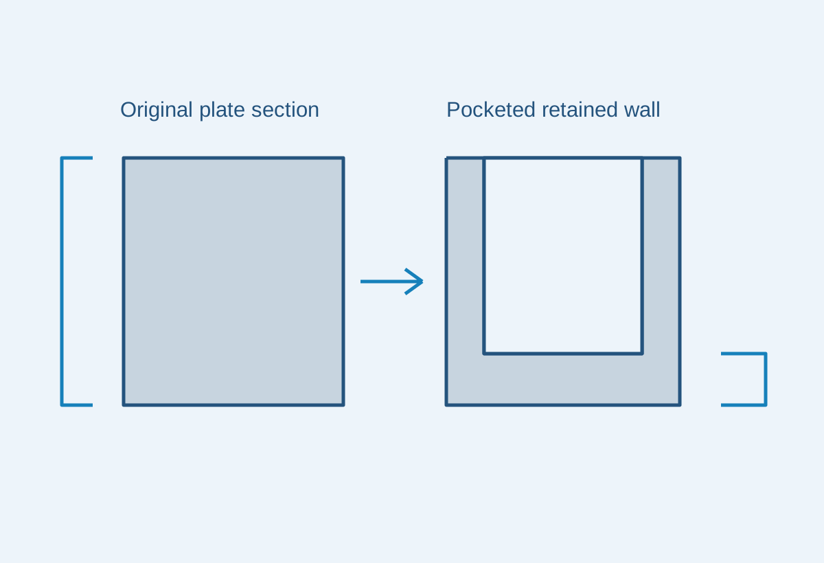
Original plate thickness remains distinct from the thin wall left after pocket machining

Read minimum and typical values separately

The reference table uses Batz+Burgel’s EN AW-7022 sheet for plate minima and selected physical values. It keeps the stock thickness and T651 condition beside the strength figures instead of presenting one strength for every 7022 part.[1]

The purchased blank retains its own material specification and order-linked identification.

7022 rolled-plate strength bands and selected physical references
ReferenceValueProduct or conditionUse in selection
Tensile / yield minima450 / 370 MPaT651 plate; >12.5–50 mmOriginal stock section
Tensile / yield minima430 / 350 MPaT651 plate; >50–100 mmThicker plate band
Tensile / yield minima410 / 330 MPaT651 plate; >100–200 mmThicker plate band
Density2.78 g/cm³Approximate; 20°CBlank and component mass
Elastic modulus70 GPaApproximate; 20°CStiffness input
Thermal conductivity130–160 W/(m·K)Approximate; 20°CThermal-design input
Linear expansion23.6 µm/(m·K)Physical referenceDimensional temperature sensitivity

Batz+Burgel EN AW-7022 sheet, September 2019. Strengths are stated plate minima Rm / Rp0.2; the first two source bands have identical strengths and are combined here without combining their elongation values. Physical properties are reference values. The actual stock specification determines the ordered material requirements.

Machining a 7022 Tooling Component

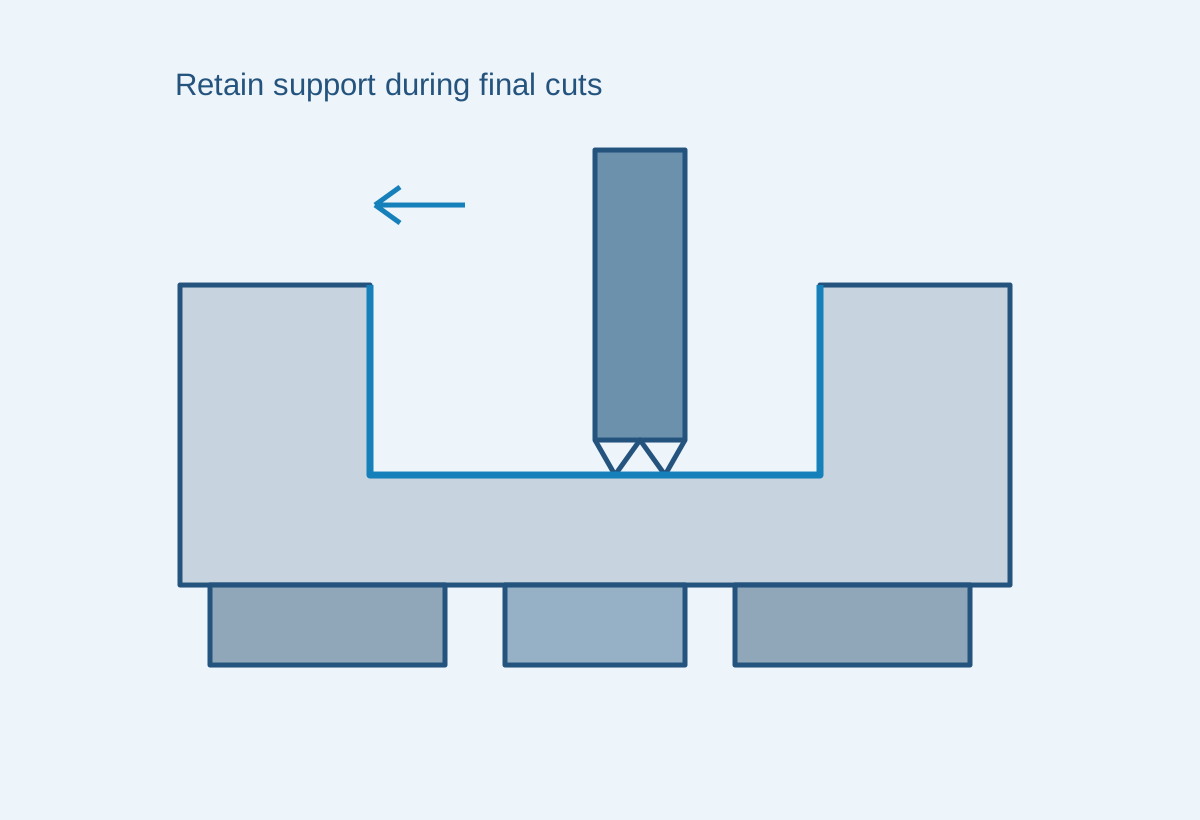
Pocketed plate supported beneath its retained floor while the final faces are machined

Establish the support and locating faces

We machine the surfaces that support the component and locate its working features. A backing face, raised mounting land and local relief can share one blank while performing different tasks.

Sequence substantial stock removal

Deep pockets and large open areas change the section left to resist clamping and cutting forces. The route can separate heavy removal from final face and bore work, with support re-established after release.

Complete bores and attachment patterns

A tool bore or circular register locates its mating component; a bolt pattern retains it. We connect those references through the setups rather than measuring every hole independently from a sawn stock edge.

Working Faces, Pin Locations and Finished Interfaces

Backing faceLocating boreAttachment holeRetained landRelief pocketFinal condition
Accept the features that locate the tool or assembly
Finished tooling features and their acceptance
FeatureRequirementAcceptance conditionCheck
Backing or mounting faceWorking area, form and datum relationshipSpecified free or supported stateFace and related features
Locating or tool boreSize and position relative to the mountCompleted componentBore and drawing datums
Pocketed bodyRetained lands and clearance geometryAfter included final operationsDrawing-defined sections
Circular registerLocating diameter and axial seatSpecified finished surface stateDiameter, face and relationship

The released component drawing defines dimensional limits and measurement support. A purchased plate’s supplied flatness or surface finish is a starting-stock condition, not the acceptance of every finished feature.

Keep the Working Interfaces Connected

We relate the tool seat, locating pattern and mounting face to the component’s specified assembly references.

7022 Component Geometry and Machining Access

Use the blank where it adds support

A large solid envelope can suit a backing plate, while an extensively hollow frame may remove most of the purchased material. The retained ribs and mounting lands decide whether that stock form is efficient.

Leave room for the finishing tool

A deep inside corner limits cutter access and stiffness. A permitted corner radius or an open approach can reduce the long-tool work required while preserving the tool’s installed clearance.

Keep material between nearby features

A large retainer bore, adjacent bolt hole and side relief all use the same local section. Their positions and root geometry must leave the material required by the released mechanical design.

Separate a replaceable wear contact

A frequently changed locating or sliding contact can use a specified insert or wear piece. The 7022 body then provides its mounting seat and retention rather than requiring every wearing surface to be integral.

Discuss Part Requirements

7022 Components in Tooling and Machine Assemblies

Tool backing and mold support

A backing component carries the adjoining tool through a defined face and fastening pattern. The support area, clearance openings and tool stack height form the useful machining scope.

Retained punches and working tools

A retainer locates the tool and transfers its reaction into the surrounding assembly. Its bore, shoulder and attachment arrangement remain distinct from the tool’s own cutting or wear requirements.

Rotary fixtures and adapter interfaces

A circular adapter translates one register and mounting pattern into another. A specified concentric reference and seating face let the fixture attach without relying on the bolt holes alone for location.

Pallets and guided handling devices

A compact body can connect locating stops, guide attachments and clamp points. The relevant support geometry follows the actual assembly, without assigning a load rating from the alloy’s tensile-strength row.

Surface Protection and Working Features

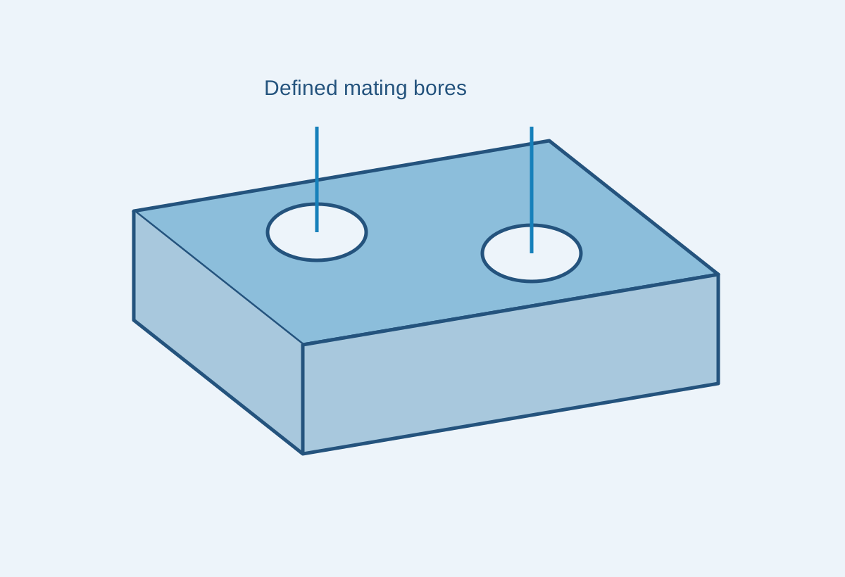
Plate diagram separating protective coating coverage from two uncoated locating bores

Protected exterior areas

Protective anodizing or another specified surface system can be included for selected areas. The appearance and environment define the treatment, rather than assuming that a high-strength plate needs one universal coating.

Registers, threads and masked lands

A locating contact can require a different surface state from the surrounding exterior. The finish boundary and final dimensions stay with the machining definition so the complete interface can be accepted.

Bore entrances and pocket edges

Deburring removes raised material while preserving the retainer seat, locating entry and narrow remaining lands. A broad cosmetic rounding operation is not applied across a functional edge indiscriminately.

Polished or visible tool surfaces

A requested polished region is identified separately from hidden support faces. The intended surface condition and acceptance govern that local work; an alloy name alone does not define a cosmetic result.

Blank Identity and Finished 7022 Geometry

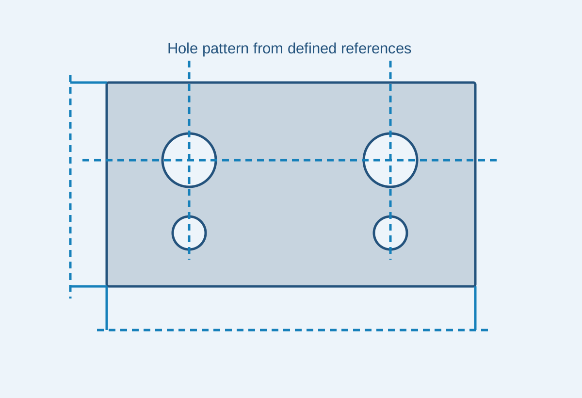
Inspection diagram relating a bore pattern to a plate edge and end reference

Retain the actual stock record

The required documentation identifies the blank’s alloy, temper, original product form and section. A general technical sheet provides selection information, while the order-linked record identifies the stock used.

Measure the released component

The locating bores, mounting face and tool contacts are checked from their specified datums in the accepted support condition. A clamped intermediate shape is not used as evidence for a different free-state requirement.

Record the final included operations

Measurements and any separately required treatment or material records follow the finished part revision. The inspection scope identifies what has actually been supplied and checked.

What Changes the Cost of a Machined 7022 Part?

Blank thickness and material utilization

A thick blank can be necessary for a raised retainer or support. If much of that section is removed elsewhere, the purchased material and cutting time increase together; a suitable near-net cutting can reduce both.

Pocket depth and working access

Deep recesses, inaccessible corners and faces on different sides add cutting directions, support and handling. Keeping useful tool access can reduce that work without altering the assembly interfaces.

Selected finishes and evidence

Local polishing, masked contacts and recorded locating dimensions add distinct operations. Applying them only to the functional or visible regions avoids carrying the same requirements across every stock surface.

Quantity and repeat preparation

Programming, fixture preparation and first-component measurements are shared across the released quantity. A repeat order can reuse that preparation when the blank product, part revision and finish remain the same.

From the Selected 7022 Blank to Repeat Components

Release the blank and finished definition

The order connects the selected 7022 product and section to the tool or machine component drawing.

Establish removal and locating sequence

The machining route sets out the heavy removal, supported contacts and final locating features needed by the component.

Accept the completed first component

The agreed checks cover the working interfaces after the included finishing, with the required support and datum references.

Repeat the approved component

The batch and later repeats retain that material, geometry and finish definition. A changed tool interface is identified as a revised component.

7022 Aluminum CNC Machining FAQs

Does the word annealed in a supplier description mean that the plate is supplied in a soft O temper?

Not necessarily. HABA describes Alu50 with low-tension annealing language, yet its product table explicitly identifies T6 for thickness below 10 mm and T651 above 10 mm. The listed temper and purchase specification therefore govern the supplied material state. Keep the actual listed temper and purchase specification instead of inferring the material state from that word alone.

Can the plate strength table be applied to a drawn or extruded bar?

Not without the relevant product basis. Wieland’s 7022 sheet separates drawn products under EN 754-2 from extruded products under EN 755-2, with different section and temper rows. A turned component starting from bar therefore uses its ordered bar specification rather than inheriting the rolled-plate table.

Does milling a thick plate down to a thin wall qualify it for a thinner plate-property band?

No. The published plate band refers to the incoming nominal plate thickness, not the local thickness left after machining. A thin rib cut from a thick blank retains the original material-product basis. Its finished dimensions and any additional property requirement are accepted separately.

Can fusion-weld repair retain the original 7022 stock-strength basis automatically?

No. The incoming plate data do not qualify a welded repair or its surrounding heat-affected region. Wieland rates conventional gas, TIG and MIG weldability as poor for this alloy. A proposed repair therefore needs an expressly accepted joining and final-property route; the original T651 stock figures are insufficient.

How can I estimate the mass of a rectangular 7022 blank?

Multiply volume by density. A 100 × 100 × 20 mm solid blank is 200 cm³; using 2.78 g/cm³ gives 556 g, or 0.556 kg. This is the defined blank mass. Pockets, bores and external profiling reduce the finished component’s volume, so its mass follows the completed geometry.

How much can a 100 mm 7022 span change between 20°C and 40°C?

Using α = 23.6 × 10⁻⁶/K as constant for this change, ΔL = αLΔT = 23.6 × 10⁻⁶ × 100 × 20 = 0.0472 mm. Wieland publishes that mean coefficient for 20–100°C. The calculation describes the stated free span; an assembled clearance also depends on the mating material, constraints and actual temperatures.

PROJECT SUPPORT

Discuss Your 7022 Tooling or Support Component

Send the part drawing, selected stock product and temper with the quantity. Include the original blank section and the working faces, bores and final finish required for the quotation.

7022 Material and Product References

The named plate, product-form and physical references used for the material distinctions above.

  1. Batz+Burgel — EN AW-7022 material data sheetPlate strength bands and selected physical reference values, September 2019.
  2. HABA — Alu50; GLEICH — CERTALCommercial rolled-plate descriptions, tooling uses and product-specific processing scope.
  3. Wieland — EN AW-7022 product dataDrawn/extruded product basis, fusion-welding assessment and 20–100°C expansion reference.
  4. Mass and thermal-length calculationsExplicit blank dimensions and temperature change with stated density and expansion coefficient.
VETCNCCNC MANUFACTURING

Get a Quote

Upload Drawing

*Required fields

Acetal part geometry illustration

Enlarged part geometry illustration

AI-generated part illustration.

English
WhatsApp Email us

Tell us about your project

Share your requirements and we will get back to you by email.

PDF, CAD or ZIP · up to 20 MB