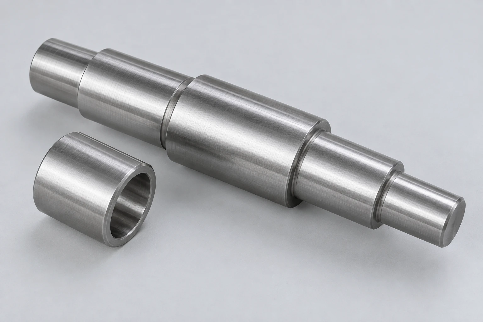
Stepped shafts and sleeves
Turned shafts carry journals, shoulders and end connections along one axis. Separate sleeves or spacers establish the required seating lengths within a drive or bearing arrangement.
Discuss this shaft
We machine custom shafts, pins, bushings, flanges, bearing housings and brackets for mining and mineral-processing equipment. Our component work supports conveyor drives, screening and feeding equipment, and plant-pump assemblies.
We supply individual mechanical parts and related spare-component sets to a released drawing. Round drive parts, bored supports and mounting components can be produced with their required mating details and finished surfaces.
Turned shafts carry journals, shoulders and end connections along one axis. Separate sleeves or spacers establish the required seating lengths within a drive or bearing arrangement.
Discuss this shaft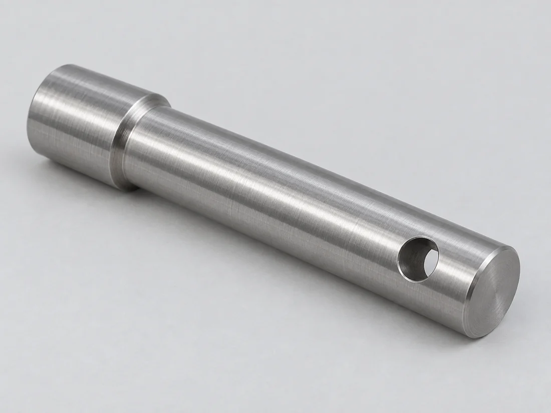
Headed or plain pins connect defined machine members. Cross holes, end threads or grooves accommodate the retaining hardware at the accessible end of the joint.
Discuss this pin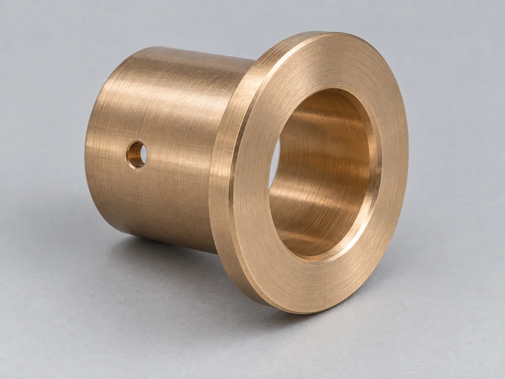
Straight and flanged bushes provide replaceable sleeve geometry within equipment joints and supports. The flange face, outside seat and internal working surface each follow their role in the assembly.
Discuss this bushing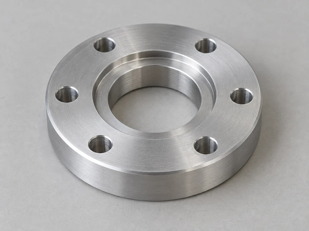
Annular adapters combine a central pilot, attachment pattern and mating face. Recesses or steps connect components with different mounting envelopes while retaining the intended axial position.
Discuss this flange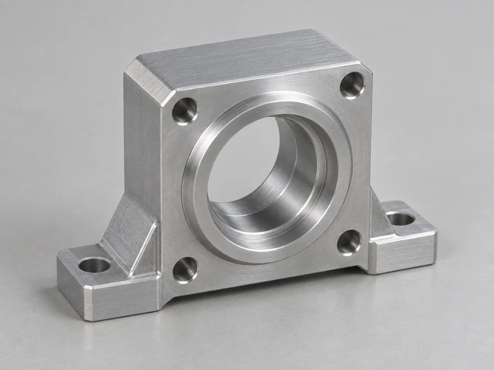
Machined empty housings locate the selected bearing or drive component relative to their mounting feet. Bores, shoulders, cover seats and attachment holes belong to the housing supply.
Discuss this housing
Milled brackets and support pieces provide stepped faces, fixing patterns and local stiffening geometry. Integral ribs or gussets can be machined as part of the component when the drawing defines them.
Discuss this bracketMineral transport, material classification and slurry transfer use different mechanical arrangements. We machine the component interfaces within those assemblies, with each part tied to its actual equipment role.
Conveyor drive parts connect the pulley or sprocket to the bearing and drive arrangement. A replacement shaft can retain the required pulley location while accommodating separate bearing seats and drive-end hardware.
A driven head-pulley shaft and an idler axle serve different roles. The drive connection and supported rotation determine which seating and end features belong on the component.
Shoulders, sleeves and end fasteners must fit within the space between the conveyor frame, bearing support and drive unit. That available stack length influences the finished component geometry.
When the pulley is retained, its hub seat and axial locating faces become mating references for the replacement shaft. A complete pulley assembly adds its own rim, hub and joining definition beyond the loose shaft.
Machined brackets, adapter faces and mounting pieces connect screen or feeder components to the intended support. A mount on the vibrating assembly has a different relationship to adjacent hardware from a mount fixed to the plant structure.
Screen supports carry equipment-specific static and dynamic forces. We manufacture the released component geometry; the equipment design establishes its section, stiffness and operating load requirements.[1]
A bracket or fixing head near a moving screen body needs the operating clearance defined by that equipment arrangement. Clearance at rest does not describe the complete movement envelope.
Fixing details and projecting edges stay outside the specified mineral-flow and liner envelope. This keeps a mounting change from introducing an obstruction at the feed or discharge area.
Plant pumps can use direct motor or gearbox drive arrangements. Shafts, spacer sleeves, mounting adapters and empty bearing housings follow the selected drive layout and its receiving components.
The drive-side hardware and the slurry-contact wet end serve different functions. A shaft support or adapter is defined by its own position in that arrangement, even when it is ordered during wet-end maintenance.
A corrosion-resistant wetted piece and a load-carrying drive part need their own material definitions. Exposure to the same plant environment does not make one grade suitable for every component.
The selected wet-end removal path can pass near the shaft support or mounting plate. Component projections must preserve that released service space without altering the drive arrangement.
The build stage determines whether the useful output is an assembly check, a finished part for equipment evaluation or repeated spares made to the same definition.
An initial shaft, housing or mounting piece can resolve seating, assembly order and access in the customer’s equipment. A fit-check piece has an identified intermediate condition if it is supplied before final treatment or finishing.
Finished first articles bring the chosen material condition, final dimensions and mating parts together for the customer’s equipment evaluation. Agreed changes become part revisions before repeat spare production.
A repeated spare batch shares programming and fixture preparation across identical parts. Heavy stock removal, long bores, multiple setups, specified treatment and added inspection coverage still increase work on each component.
Strength and hardness describe different aspects of a material. The named product forms below help compare shaft steels, a bearing bronze and corrosion-resistant flat stock for the component’s defined role.
| Material / condition | Published reference | Component role |
|---|---|---|
| 42CrMo4 · Ovako 327A +QT | Rm 900–1100 MPa; 270–320 HB | Specified shaft and pin components |
| C45 · Ovako 5081 +QT | Rm 630–780 MPa; 185–235 HB | Shafts, spacers and general machine parts |
| C93200 · continuous cast | Rm ≥241 MPa; 65 HB typical | Machined bearing bushes and sleeves |
| 316L / 1.4404 · solution annealed | Rp0.2 ≥170 MPa; Rm ≥485 MPa | Corrosion-exposed plate-based parts |
Rm: tensile strength; Rp0.2: 0.2% proof strength. Ovako values are for the named +QT round-bar variants, 40 < round-bar stock diameter < 100 mm. C93200 values follow Wieland Concast’s ASTM B505/B505M-23 continuous-cast data; HB 65 is typical at a 500 kg test load. Outokumpu 316L values are ASTM A240 flat-product minima at 20°C. Component load capacity and wear life are established on the component, under its own duty.
We plan the cutting route around the component’s axis, mounting datums and feature access. A round shaft, a bored housing and a bracket with side features require different setups.
Turning produces stepped diameters, annular recesses and seating faces. Related diameters and shoulders can be established from a common rotational datum before the component receives its secondary features.[3]
CNC turning servicesMilling produces mounting feet, bored support geometry, piloted flange patterns and stiffened brackets. Tool access around ribs and recessed faces influences how the part can be held and finished.
CNC milling servicesIndexed or secondary operations add cross holes, keyways and features on several faces. The setup retains a defined relationship to the primary shaft axis or mounting datum instead of treating each face independently.
5-axis machining optionsThe component has to locate its mate, retain the required movement and support the selected seal arrangement. Four different relationships define those functions.
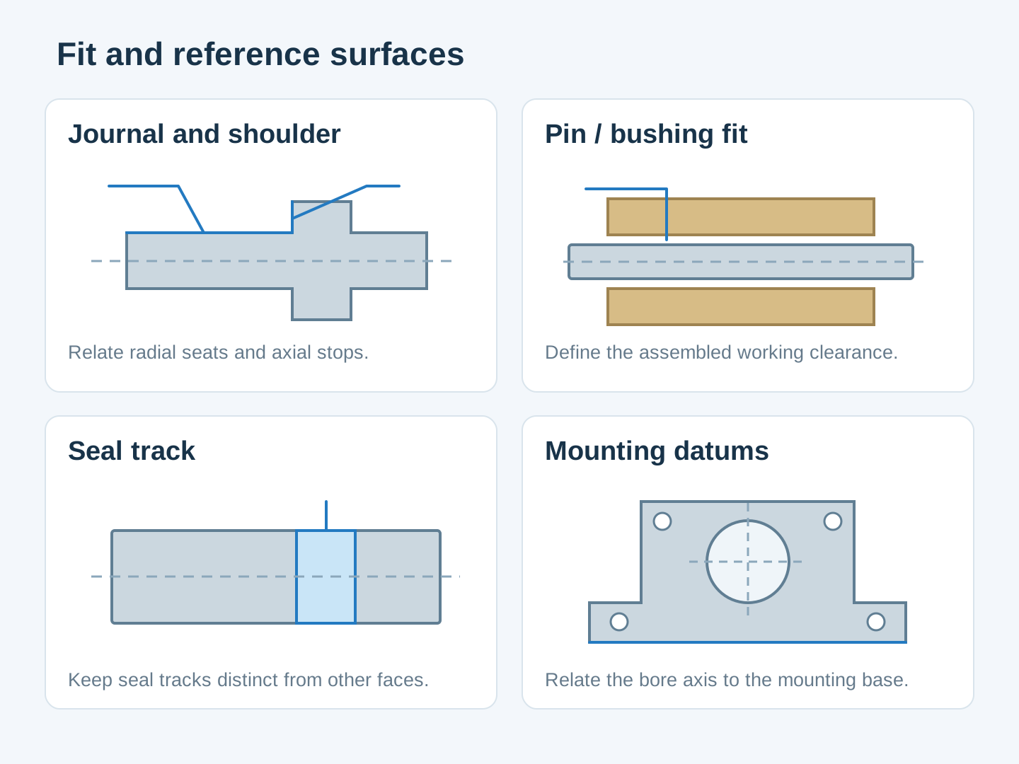
The journal centers the selected rotating component; its shoulder establishes an axial stop. The adjoining radius and mating chamfer need clearance so the component seats on the intended face.[4]
The working diameter and the surrounding bush seat are separate interfaces. Retention details must also allow the movement defined by the equipment joint without clamping across that movement.
A rotating seal needs its specified running texture over the actual lip-contact zone. A correctly finished track in the wrong axial position still leaves the lip on a shoulder, groove or unfinished surface.
The bore axis is related to the mounting face and fixing pattern. These relationships determine where the supported shaft sits after the housing or bracket is attached to the equipment.
The drawing separates working surfaces from general exterior surfaces. We keep the machining sequence and final surface condition connected to those functions.
Quenched-and-tempered material condition and any specified local treatment belong to the part definition. Operations that can alter a working diameter are placed before its final dimensional acceptance.
Paint or another specified protective coating can cover exposed housing and bracket surfaces. Fits, locating faces and designated contacts retain the required coated or masked condition.[5]
Cross-hole exits and intersecting features need the specified burr-free edge condition. An indiscriminate edge break must not remove a retaining edge or change a defined shoulder transition.
We inspect the drawing-defined sizes and datum relationships on shafts, bushes, flanges and housings. Finished fits are evaluated after the operations affecting them.
The table separates dimensional limits, seal-track texture and material condition. The selected bearing, seal and component drawing establish which reference applies.
| Part / feature | Applicable reference | Acceptance detail |
|---|---|---|
| Shaft diameter: >30–50 mm, h6 | −0.016 / 0 mm deviation | Final diameter after specified treatment |
| Bore diameter: >30–50 mm, H7 | 0 / +0.025 mm deviation | Finished bore in its specified acceptance state |
| Radial shaft-seal track | Ra 0.2–0.8 µm, DIN reference | Actual lip-contact zone to the selected seal specification |
| Housing or bracket location | Drawing-defined position and runout | Bore axis and fixing pattern to the designated mounting datums |
| Heat-treated shaft or pin | Specified grade, condition and hardness | Material record and required hardness location identified |
Size deviations apply to the selected ISO 286 class in the nominal band >30 through 50 mm; they do not prescribe the fit for every bearing or bush. Ra is SKF’s DIN-column reference for a radial shaft-seal counterface; the selected seal specification governs. Geometry and material acceptance follow the component drawing.
Component inspection supports the released part definition. Screen dynamics, drive alignment, fatigue life and complete-machine qualification remain separate equipment-level acceptance requirements.[6]
Spare components may be stored before installation or travel beside heavier machine parts. We protect the finished interfaces and keep the supplied condition identifiable.
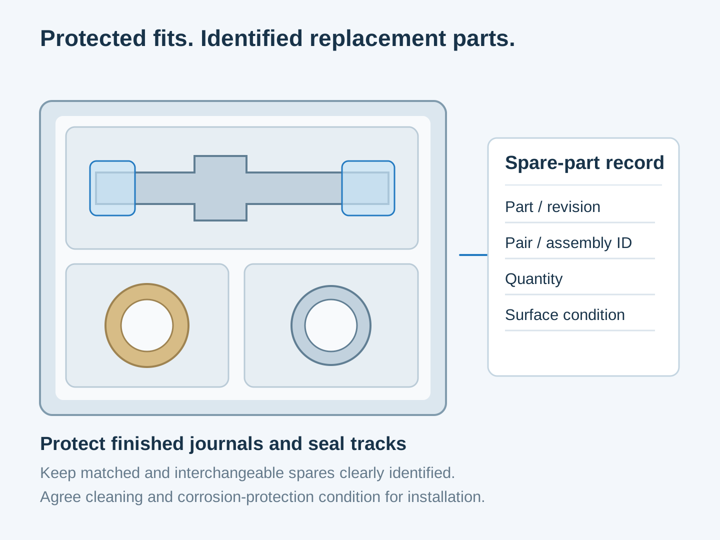
Separate packing limits contact against shaft journals, seal tracks, bush bores and flange pilots. Local protection keeps those surfaces from becoming load-bearing contact points inside the package.
Part numbers and revisions distinguish shafts with different end details, sleeve lengths or mounting patterns. Identification remains with each component when a mixed spare set is unpacked.
The supplied condition states whether the component is finished for assembly or awaits an agreed secondary operation. Temporary corrosion protection and any removal before assembly are identified with that condition.
It can help identify the part, but wear, previous rework or deformation may have changed its geometry. The original part reference and released mating requirements establish the new dimensions. Copying an enlarged bore or worn pin diameter would reproduce the used condition rather than the intended replacement.
Hardness alone is not a substitution rule. An abrasion-resistant plate such as Hardox 400 has a different product specification from a quenched-and-tempered shaft bar. Section, strength, toughness and the component’s treatment requirements still have to suit the shaft design before a different grade is released.
Yes, when the housing design uses matched halves. SKF’s SNL guidance uses matching identification on the cap and base because the assembled parts establish the housing bore. A replacement cap cannot be assumed interchangeable solely because its bolt pattern and outside shape look the same.
No. Runout describes geometric variation relative to an axis; balance concerns the rotating mass distribution. ISO 21940-11 addresses residual unbalance for rotors with rigid behavior. A rotating assembly that requires balancing therefore needs its own defined acceptance, in addition to the shaft’s dimensional checks.
Not always. A separately selected wear sleeve can provide a new counterface for a radial shaft seal. Its use depends on the shaft condition, available space and the selected sleeve and seal arrangement. That repair option is a different component decision from manufacturing a complete new shaft.
No. The keyed, splined or other drive form, engagement length, axial stop and retention arrangement also establish the connection. A matching outside diameter can still leave a coupling unable to engage or seat. The complete released interface must match the selected drive hardware.
Material, equipment-interface and acceptance references used on this page.
Share the component drawing and identify its position in the conveyor, screen, feeder or pump assembly. We will quote the machining and required finished delivery scope.
Drawing revision, material condition, mating reference and the finished dimensions to be supplied.
Quantity for each part identity, including handed versions, different shaft ends or separate sleeves.
Specified treatment or coating, acceptance records, timing and the next receiving operation.
We can review an individual spare or a related set of components for the same equipment assembly.
We use Google Analytics to see how this site is used. Analytics cookies are set only if you accept. Privacy Policy
