On this page
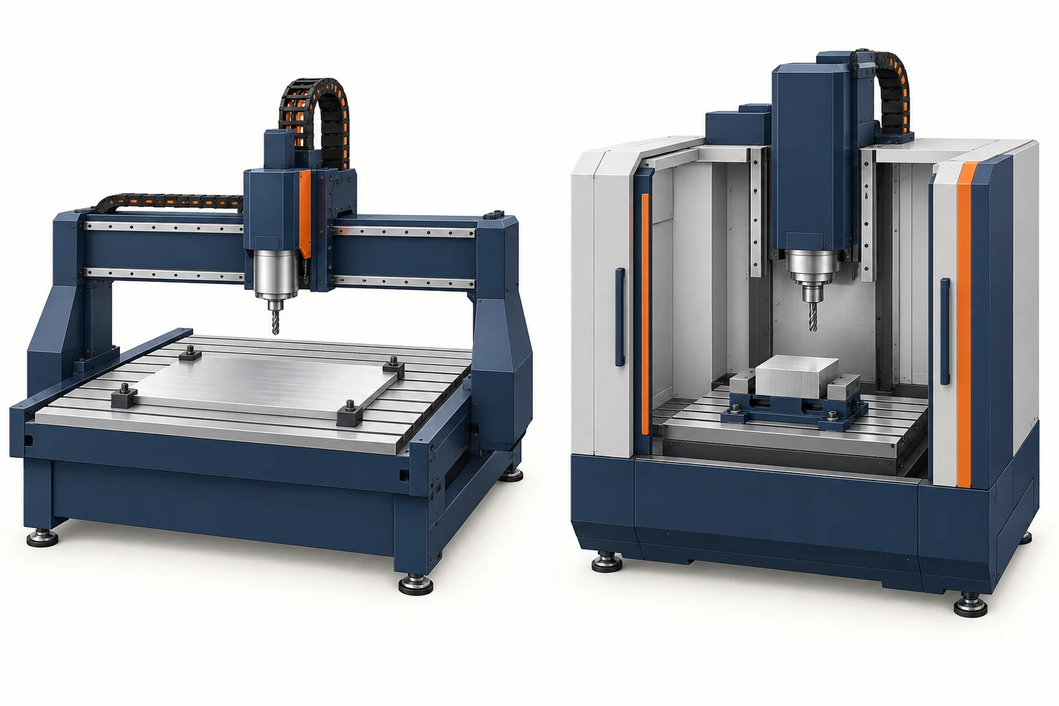
A CNC router and a CNC mill both remove material with a rotating cutter under programmed control. The useful difference is the work they are designed around. Routers commonly emphasize broad work areas and efficient processing of sheets, panels and nonferrous materials. Metal-cutting mills commonly emphasize rigid support, versatile workholding and demanding features in blocks or castings. Their capabilities overlap: an industrial router can be a serious aluminum-machining system, and a high-speed mill can excel at sheet work.
Compare the part, cutting task and configured machine together. “Router” or “mill” alone does not establish material limits or finished-part accuracy.
What the two names tell you—and what they leave open
A router is more than an engraving machine: suitable configurations can profile outlines, mill pockets and machine holes. A milling machine performs the same basic material-removal process, with equipment ranging from small mills to large machining centers. These common design priorities help explain the comparison:
| Design priority | Common router emphasis | Common metal-cutting mill emphasis |
|---|---|---|
| Work format | Large sheet or panel area; multiple parts arranged across the stock. | Blocks, castings or fixtures arranged for the required machining faces. |
| Spindle and tools | High-speed cutting with tools matched to the material and engagement. | A speed and torque range suited to varied milling, drilling and hole-finishing operations. |
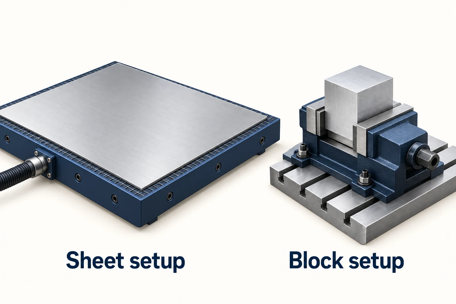
| Workholding | Distributed sheet support, often with vacuum or dedicated fixtures. | Vises, clamps, pallets or dedicated fixtures; vacuum is also possible. |
These are starting points, not defining restrictions. C.R. Onsrud describes its E-Series industrial router as a fixed-bridge system for substantial cutting in nonferrous metals and composites. Conversely, the systems described in DATRON’s High-Speed Machining overview combine high spindle speeds with workholding aimed at aluminum and other nonferrous parts. Neither a gantry silhouette nor a high RPM rating reliably separates the two categories.
Rigidity is resistance to deflection under load. The relevant chain includes the frame, guides, spindle, holder, cutter, workpiece and fixture. A substantial frame does not cancel the flexibility of a long cutter or a poorly supported part. Evaluate the loaded arrangement at the feature being machined. Sandvik Coromant’s Indexable milling tools catalogue 2025 selection guide treats tool overhang and stability as process variables; it does not assign a universal accuracy class to a machine label.
Match spindle behavior to the cutter and material
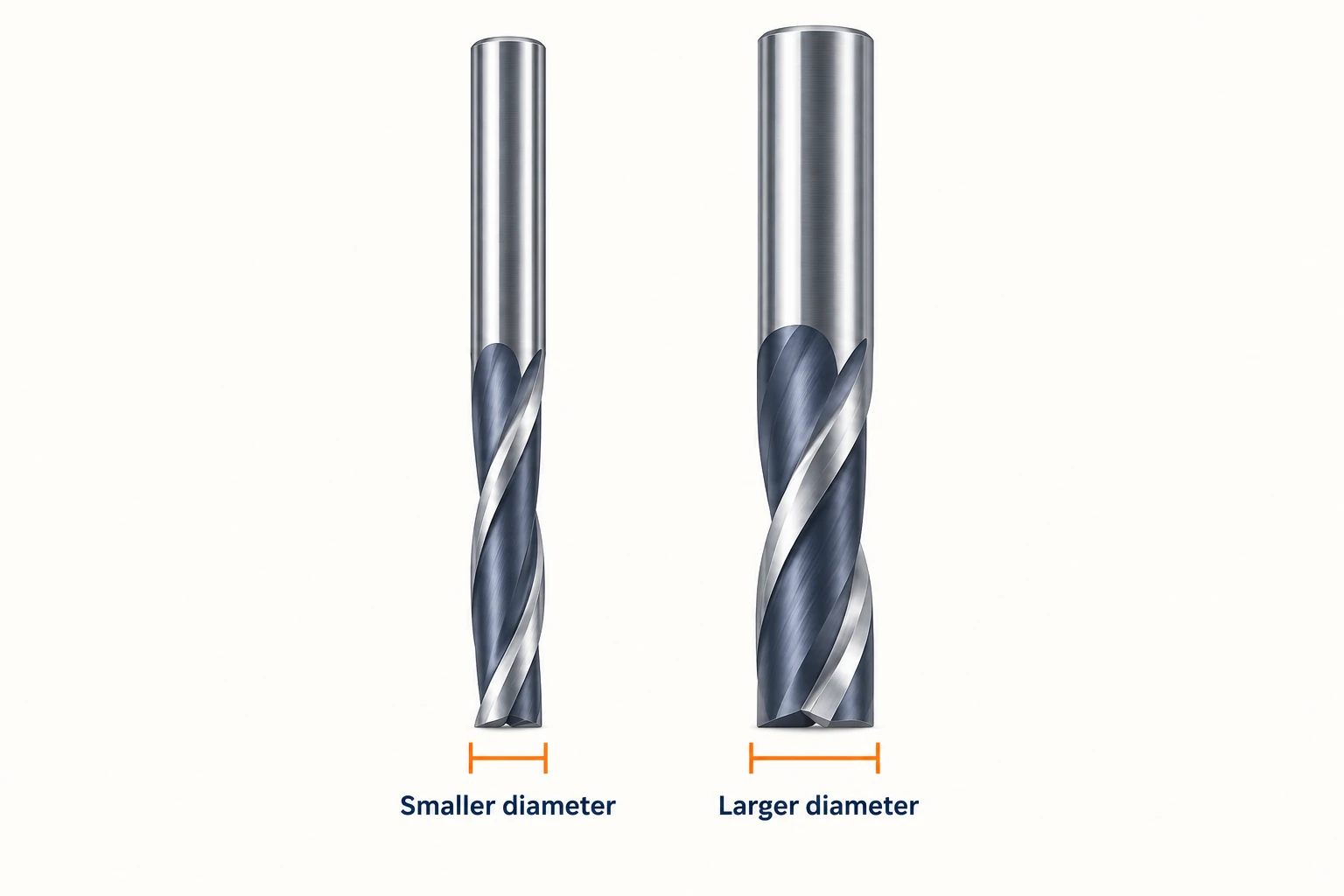
Spindle speed is rotation rate. Cutting speed is the speed of the cutting edge relative to the work. At the same RPM, a larger cutter has a higher peripheral cutting speed because its circumference is larger. A small cutter may therefore need a high spindle speed to reach its intended cutting speed.
That is one reason high-speed systems suit many small-tool aluminum operations. It does not mean the highest RPM is always preferable. Tool geometry, diameter, material, engagement and the toolmaker’s cutting data determine the operating range. A spindle’s available torque at that speed matters too: its peak power rating does not establish how it will perform at a much lower speed.
The programmed feed must match the tool and cutting conditions. Increasing RPM while leaving feed unchanged reduces the nominal feed per tooth; it does not automatically improve the cut. Use the relationships between speed, diameter and feed per tooth in the milling-formula section of Uddeholm’s Vidar 1 — Cutting data recommendations to compare compatible conditions, rather than comparing maximum spindle speeds in isolation.
Three aluminum parts can point to different choices
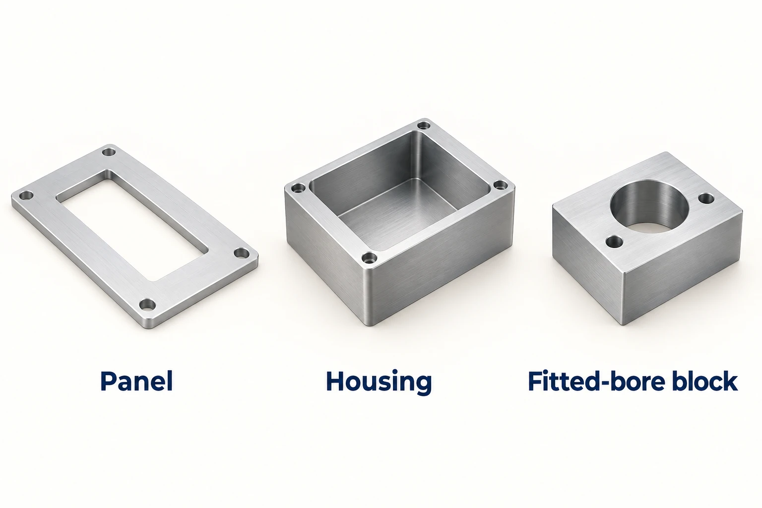
Consider three hypothetical jobs made from 6061-T6 aluminum. Keeping the alloy and temper the same makes the effect of geometry easier to see.
A flat panel with cutouts and shallow recesses
A router configured for aluminum is a plausible starting point when the work is distributed across a broad sheet. Several outlines can share one stock setup, and distributed support can help hold the panel. The deciding details include underside clearance for through-cuts, chip removal, and how each small part remains secure as its outline is completed. A suitable high-speed mill with enough working area can serve the same task.
A thick housing with deep pockets
Here the machine must accommodate the stock, fixture, holder and required tool reach. Sustained material removal, chip evacuation and wall stability become more important than sheet coverage. A machining center configured for this work is a sensible starting point. The housing does not automatically exclude an industrial router: compare the actual head clearance, stiffness, tool access and cutting capability. The word “deep” is not a universal boundary between the categories.
A compact block with a fitted bore and related mounting faces
The critical issue is the relationship between the bore and its reference faces. Workholding, the finishing operation and the measurement plan must preserve that relationship. A metal-cutting mill with an appropriate fixture may offer a convenient route. Another machine can still qualify if its complete process meets the drawing. Neither a smooth-looking surface nor a machine’s positioning figure proves the required bore size or alignment.
The material changes the comparison too. Substantial steel cutting generally points toward equipment explicitly designed for that load and operating range. Plastics are processed on both routers and mills; stock support, heat, chip removal and the particular polymer still matter. Material names narrow the process choices, while the features and working conditions determine the remaining fit.
Workholding can decide the job before spindle power does
Vacuum workholding leaves the upper surface accessible and can support flat stock over a broad area. It appears on both routers and mills. What matters is the effective area over which a pressure difference is maintained—not the machine table’s overall size.
To isolate the area effect, assume an ideal, maintained pressure difference of 80 kPa, equal to 0.08 N/mm². Compare two sealed areas using normal holding force ≈ pressure difference × effective area:
| Assumed effective sealed area | Area | Ideal normal holding force |
|---|---|---|
| 100 mm × 100 mm | 10,000 mm² | 0.08 × 10,000 = 800 N |
| 20 mm × 20 mm | 400 mm² | 0.08 × 400 = 32 N |
Reducing both side lengths to one fifth reduces the area—and this ideal force—to one twenty-fifth. The figures are not allowable cutting loads. Resistance to sliding also depends on friction and any mechanical restraint; leaks or an opened seal can reduce the pressure difference. Schmalz’s Vacuum Clamping Technology guidance distinguishes normal force from lateral holding force and requires the actual machining loads and holding conditions to be assessed.
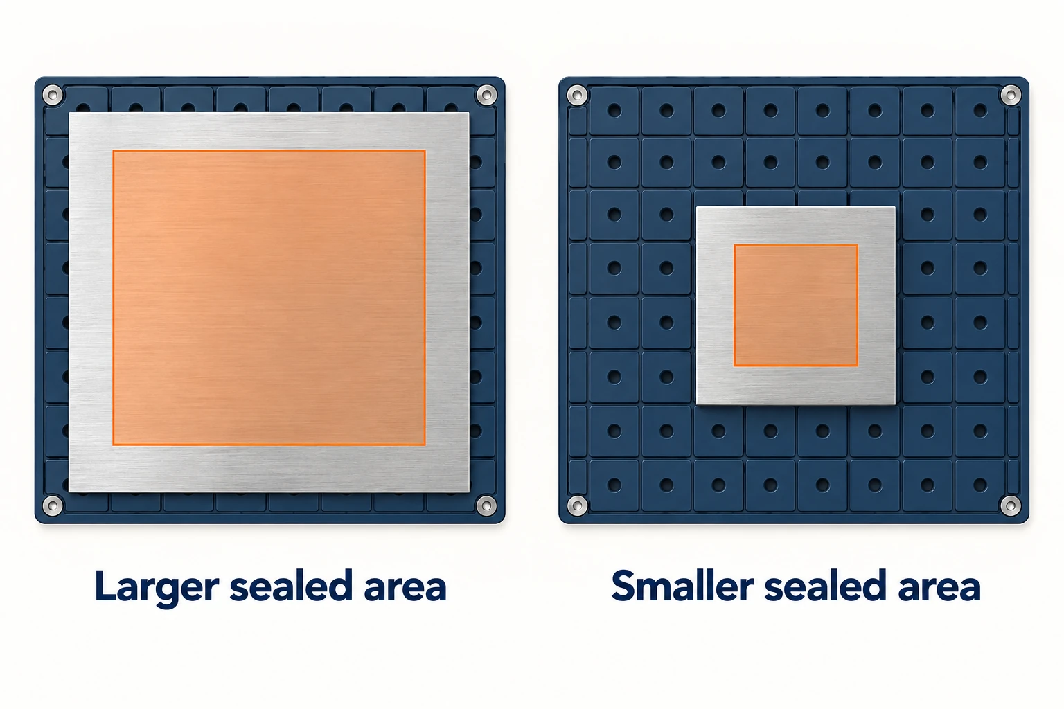
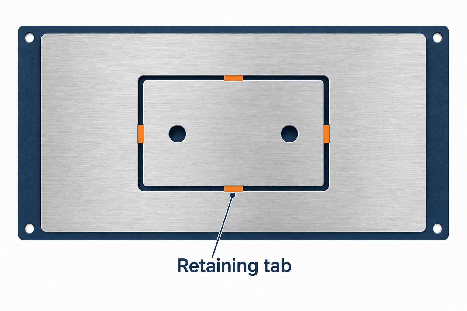
This becomes especially relevant near the end of a profile cut. The original sheet may be well held while the small part being separated has far less effective holding area. Cutting through a sealing region may also change the vacuum condition. Plan retention for the individual part at that stage, rather than assuming the initial sheet setup remains equivalent.
Depending on the part, the process may leave small connecting tabs for removal in a later operation, retain a thin uncut layer for subsequent finishing, or use a dedicated fixture that holds the individual piece. Each choice changes edge finishing, handling and sometimes the number of setups. The CAM toolpath and fixture need to agree about when the part becomes independent of the surrounding stock.
Compare the complete route to the finished part
Start with the same drawing, material condition, quantity and inspection requirements. Then compare setup effort, cutting access, retention, finishing and verification. A router may be an efficient choice for a panel while a mill is convenient for a fitted block; an overlapping industrial configuration may suit both. A lower machine purchase price or faster rapid-traverse figure does not settle the cost of the finished part.
For outsourced CNC milling, the useful discussion is how the proposed process will make and verify the required features. The machine category helps explain that proposal; the complete process determines whether it fits the job.
Frequently asked questions
Can a CNC router machine aluminum?
Yes, when the machine, tool, workholding and cutting conditions suit the job. Industrial routers can perform substantial aluminum machining. Sheet profiles, deep pockets and fitted features place different demands on the setup, so “can cut aluminum” is only the start of the assessment.
Is a CNC mill always more accurate than a router?
No universal accuracy ranking follows from the names. Finished-part results depend on the machine configuration, tool reach, workholding, thermal condition, finishing process and inspection. Compare the required feature under its actual machining and measurement conditions.
Can a CNC router machine three-dimensional shapes?
Yes. A suitable router can machine pockets and three-dimensional contours using coordinated motion. Its usable depth and access depend on the head, travel, tool assembly, stock and fixture. Additional controlled rotary axes can expand access where the configuration supports them.
Can routers and mills use the same cutting tools?
Sometimes. Compatibility depends on the holder interface, shank size, tool retention, rated speed, geometry and intended material. A cutter that fits the holder still needs suitable cutting data and clearance for the operation.



