On this page
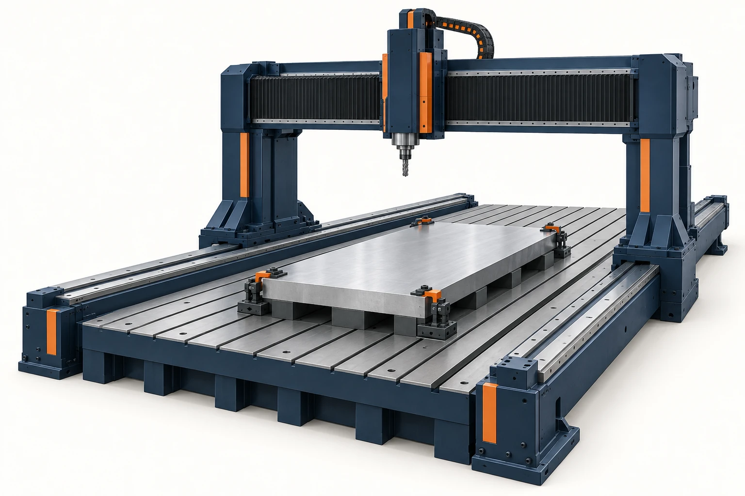
A CNC gantry milling machine carries its cutting head on a bridge spanning the work area. That layout makes room for long plates, machine bases, molds and other substantial components with the crossbeam supported at both ends. In a moving-gantry design, the workpiece stays on a stationary bed as the portal travels along it. Related fixed-bridge machines move the table and workpiece instead.
The useful question is what this arrangement changes for the job: which mass moves, how the tool reaches each face, where the part is supported, and how dimensions are checked across its length.
Start with what moves beneath the bridge
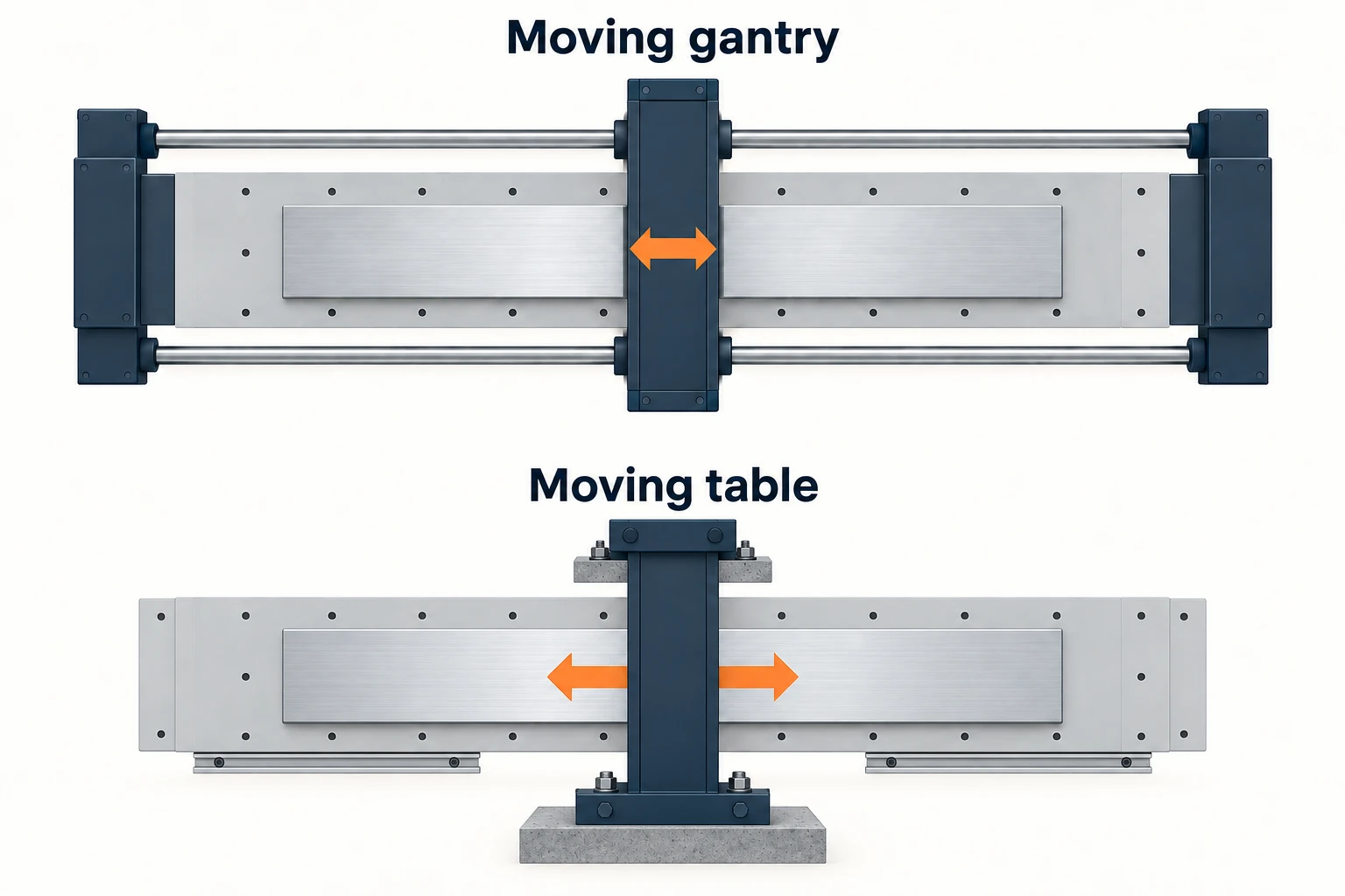
“Gantry,” “bridge” and “double-column” describe related structures, but they do not uniquely identify the motion layout. Nicolás Correa, for example, separates its Gantry Type Milling Machines from its Bridge Type, Moving Table Milling Machines. Look at the machine arrangement as well as its name.
| Arrangement | Longitudinal movement | What it changes for a large part |
|---|---|---|
| Moving gantry, stationary bed | The portal travels along guideways beside the work area. | The workpiece and fixture are not accelerated by that axis. A long bed can support an extended setup, while clearance is needed for the traveling structure. |
| Fixed bridge, moving table | The table carries the clamped workpiece beneath the portal. | The axis moves the table, fixture and workpiece together. The installation must accommodate the table’s full swept space. |
A stationary workpiece can be useful when the setup is especially long or heavy. It does not remove the limits of the bed, foundation or local support points. Conversely, a moving table is not restricted to light work: its capacity depends on the actual machine design.
The overhead structure also changes loading access. A part may fit between the columns yet still require a particular approach for placement, head clearance or fixture assembly. Use the installation layout to understand those movements; the table rectangle alone does not describe the space needed around the machine.
The bridge helps only if the cutting head can reach
A large working area brings widely separated features into one setup. Both mounting pads on a long base can then be machined from the same established reference, reducing the need to transfer their relationship through another setup. The remaining question is whether the complete tool assembly can approach every required surface.
A vertical spindle can address an exposed top face. A side-facing bore may need an angle head, an orientable milling head or a different setup. The space occupied by the head and holder matters as much as the cutter tip: a reachable point is not automatically a clear approach. Correa’s Milling Heads overview illustrates how indexing and contouring heads serve different access and motion requirements.
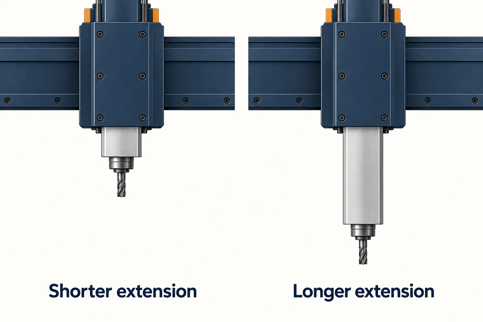
On many large machines, the spindle is carried by a ram, a sliding member extending from the head support. Extra extension reaches down toward the work, but unsupported reach makes stiffness a practical concern. Where the crossrail height is adjustable, check whether a lower support position can reach the same feature with less ram extension and adequate clearance.
There is no universal accuracy ranking based on the word “gantry.” Crossbeam and ram sections, guide support, spindle assembly, tool projection and the chosen cutting conditions all influence behavior. Compare the arrangement at the actual working position, including the deepest reach, rather than assuming a broad bridge makes every tool position equally stiff.
Support the workpiece where the forces enter it
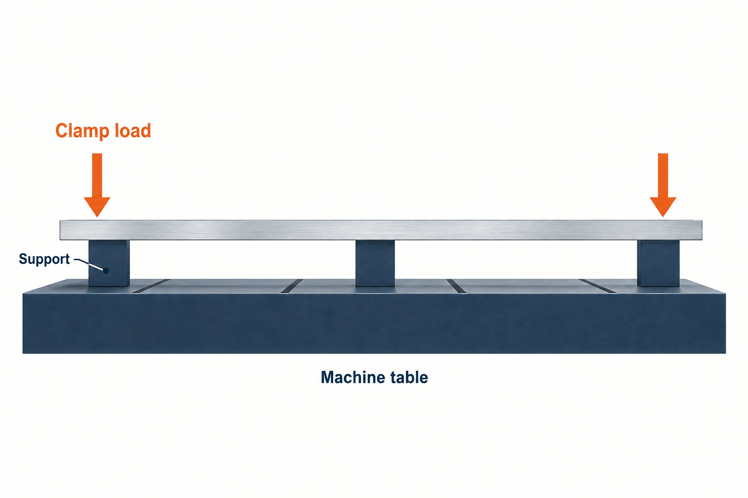
The machine structure and the workpiece support solve different problems. A stiff portal cannot prevent a long, thin plate from bending between its supports. A broad base can also rock on uneven contacts or change shape when clamped.
Plan the locating surfaces first: these establish the workpiece position. Then consider support beneath the cutting region and close to the clamp forces. Carr Lane’s Locating & Clamping Principles explains why loads should be directed into supported regions rather than used to bend the work into place.
For example, tightening a clamp above an unsupported edge can pull that edge down. Machining the top flat in that condition does not establish that it will remain flat after release. Additional supports can help resist load, but their position and adjustment must suit the part; simply adding more hard contact points can create a different seating problem.
Keep three conditions distinct: the raw part resting on its supports, the clamped part during machining, and the part in the condition required for inspection. If clamp release changes a critical feature, the process needs to account for that change. More machine travel will not solve it.
A small temperature change matters across a long dimension
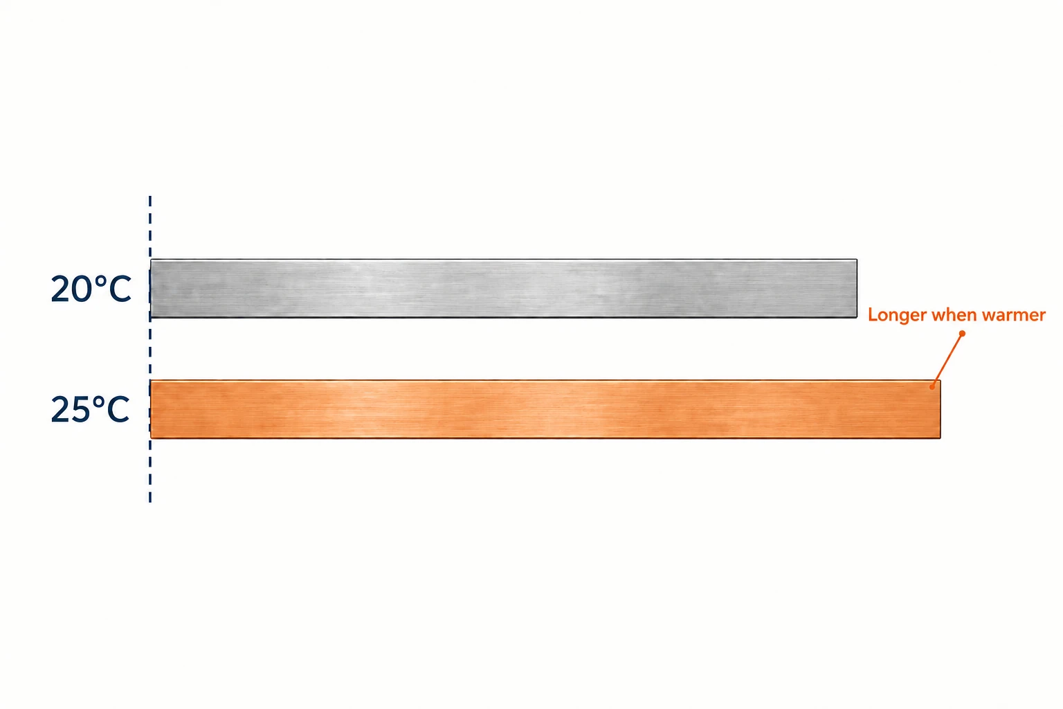
Large parts make thermal expansion easier to notice because the length change grows with the measured span. A dimensional result also depends on the workpiece temperature, the measuring system and the temperature distribution through the part. Mitutoyo’s Temperature and Dimensional Measurements explains why stabilization and the reference temperature belong in dimensional measurement planning.
Consider a hypothetical 6061 aluminum base that is 2,000 mm long at 20°C. Assume it expands freely and uniformly to 25°C. Adopt a constant expansion coefficient of 23 × 10−6/°C, the value listed for 6061 over 20–100°C in Constellium’s 6061 material sheet.
Length change ≈ original length × expansion coefficient × temperature change
ΔL ≈ 2,000 mm × 23 × 10−6/°C × 5°C = 0.23 mm.
This estimates workpiece growth under the stated assumptions. It does not predict machine drift, clamping restraint or bending from a temperature gradient. It does show why comparing a warm part with a nominal dimension referenced to 20°C can be misleading unless the measurement accounts for temperature.
Plan when the part is measured and how its thermal condition is established. A probe on the machine is useful for locating and process checks, but it shares the machine’s geometric and thermal behavior. The final verification method must suit the required tolerance and inspection condition.
Turn the machine layout into an operation plan
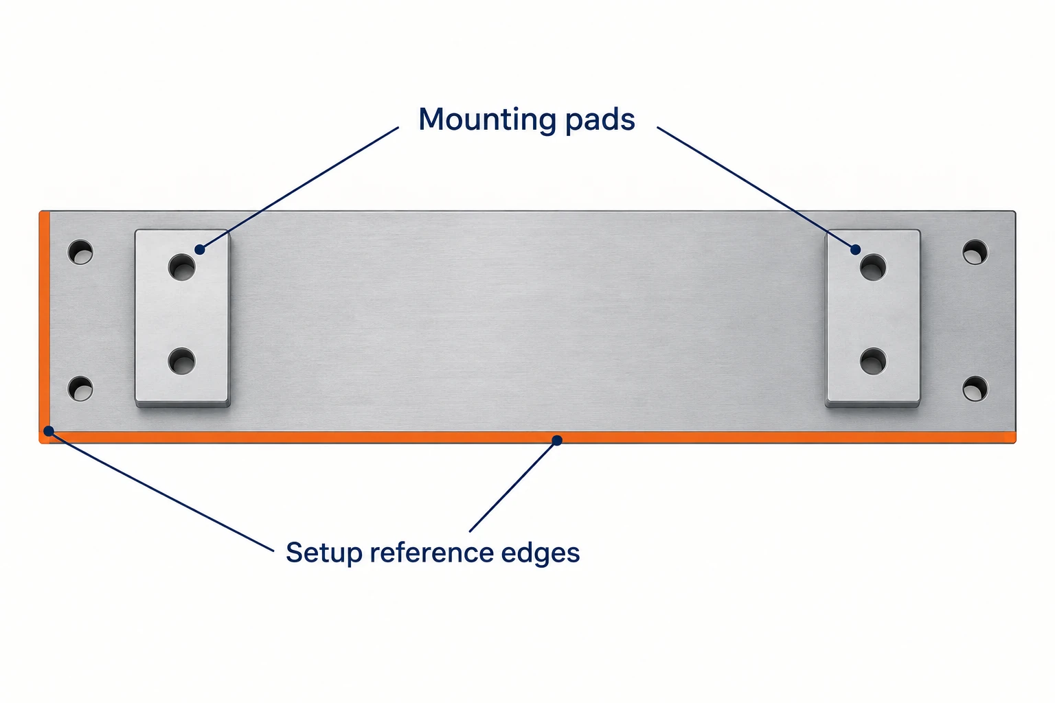
Take the same long base, now with a mounting pad and hole group near each end. The gantry’s useful contribution is access to both regions within a common setup. The operation plan must preserve their relationship through material removal, finishing and measurement.
- Locate and support. Choose setup references consistent with the drawing’s datum scheme; place supports and clamps clear of both machining regions. Both ends start from a defined, stable seating condition.
- Rough the features. Sequence material removal with enough stock for later finishing, and observe whether the part changes shape. A large work area does not prevent movement as material is removed.
- Establish the finishing condition. Check seating and temperature. If the part must be released or repositioned, re-establish its location before finishing. The finishing program must reference the part’s current position and condition.
- Finish and verify. Finish the related pads and hole groups, then measure their relationship in the specified datum and support condition. Local dimensions alone do not establish alignment across the complete base.
This is a planning example, not a fixed machining sequence for every casting, plate or weldment. Its point is to connect machine access with part behavior. If the underside is blocked by supports or a side feature cannot clear the head, another operation may still be necessary.
A useful gantry setup combines enough working space with suitable head access, stable workholding and a credible measurement plan. Those elements explain how the machine supports large-part machining more clearly than its overall size alone.
Frequently asked questions
Does a gantry CNC machine always have five axes?
No. Gantry describes the supporting structure. A machine can use three linear axes, while additional controlled rotary motions may provide indexed or simultaneous five-axis capability. The head and control configuration determine what it can do.
Does the workpiece stay still on every bridge-type machine?
No. A moving-gantry arrangement carries the portal over a stationary workpiece. A fixed-bridge arrangement can move the table and workpiece beneath the portal. Check the actual axis layout because manufacturers use related names for different configurations.
Can a gantry machine finish every side in one setup?
Only the faces that the installed head and tool assembly can reach with adequate clearance. Supports and clamps may hide the underside, and side features may require an angle head or another setup. A wide bridge does not make every surface accessible.
Can on-machine probing replace the final inspection of a large part?
It depends on the inspection requirements and the validated measurement process. Probing supports setup and process checks, but shares the machine’s error sources. Critical dimensions may need verification in a different support or temperature condition, or with an independent measuring system.



