On this page
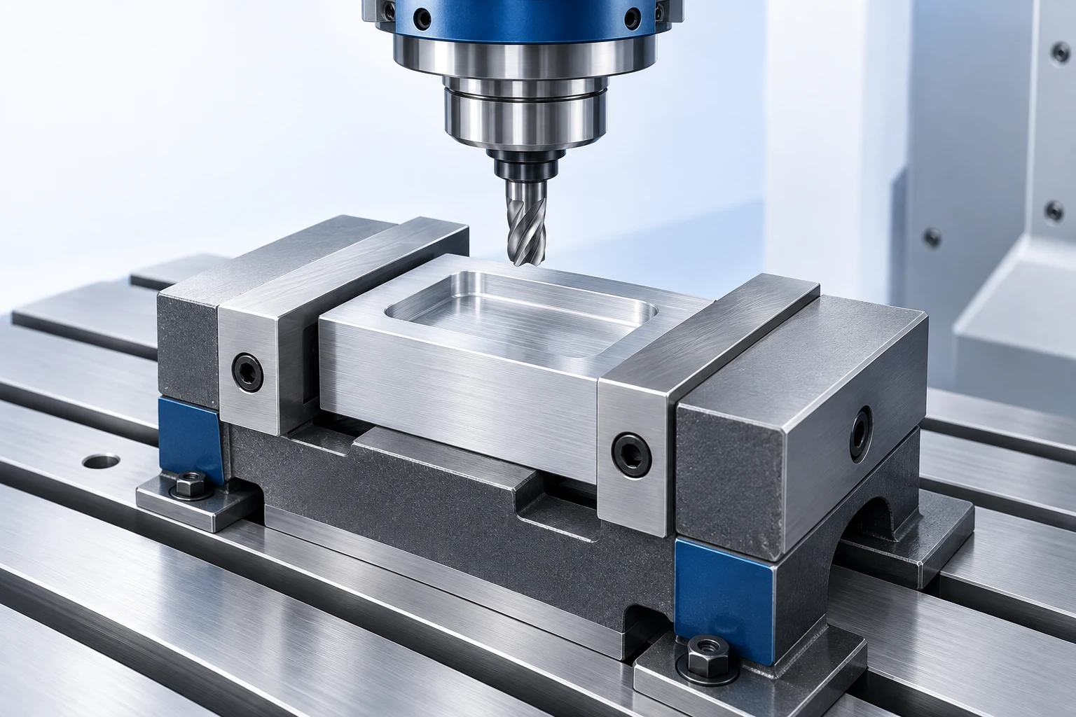
CNC tooling and workholding form the connection between a machine’s motion and the finished part. Cutting tools remove material; tool holders connect them to the machine; workholding locates, supports and restrains the workpiece. A suitable cutter can still produce a poor result if its holder is too bulky to reach the feature, the part moves under load, or chips prevent it from seating correctly.
The practical choice is therefore a complete setup. This guide explains how to evaluate that setup, compare common holding methods, and connect cutting conditions with access and inspection. It is intended for engineers and buyers discussing a proposed manufacturing route, as well as readers learning why the same machine can need different tooling for different parts.
What belongs in a CNC tooling system?
“Tooling” can mean cutting tools alone or a wider collection of production equipment. In a quotation, ask what the term includes. A replaceable insert, a custom form tool, a pair of machined jaws and a dedicated fixture are different purchases with different replacement and reuse implications.
Think through the connections in order: machine spindle or turret, tool holder, cutting edge, workpiece, fixture and machine table or work spindle. Each connection must provide the required fit, access and resistance to cutting forces. Measurement then establishes whether the resulting features meet the drawing. Neither an expensive cutter nor an accurate machine specification establishes the performance of the whole chain.
Start with the feature and cutting operation
A pocket, a drilled hole and an external turned diameter need different cutting actions. In conventional milling, the cutter rotates; in conventional turning, the workpiece rotates against a tool held in the turret. Machines with live tooling can combine operations, but the individual tool still has to suit the cut. Our explanation of how CNC milling works develops the milling motion in more detail.
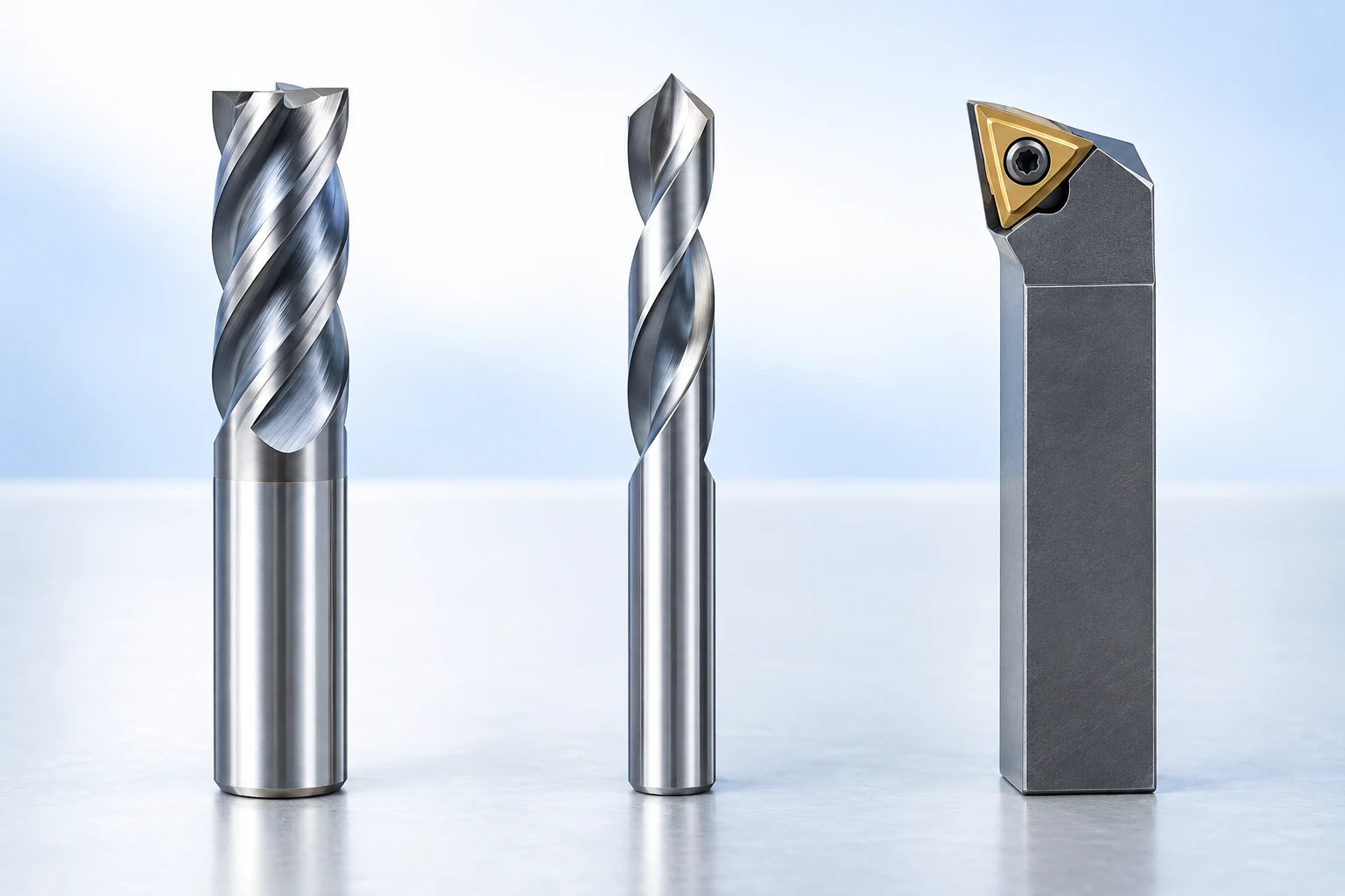
For milling, distinguish the end profile, cutting diameter, flute arrangement and usable cutting length. A square-end profile and a ball nose produce different contact geometry. Flutes also provide space for chips, so adding cutting edges is not automatically an improvement. Harvey Performance’s The Anatomy of an End Mill explains these separate features. [1]
Material designation and condition belong in this decision. “Steel” is insufficient to establish whether a cutter or insert is appropriate. The operation, alloy and hardness or heat-treated condition influence the applicable tool guidance. For a turning insert, shape, grade, chipbreaker and nose radius must work together; a finishing geometry should not be assumed suitable for a heavy interrupted cut simply because it fits the holder. [2]
A useful first comparison is a broad pocket with a small internal corner. A larger cutter may remove the open material efficiently, while a smaller tool is needed to finish the corner. Selecting the small tool for every pass can solve access at the expense of a less efficient roughing route. Selecting only the larger tool leaves the corner unfinished. This is why a tool list should identify what each cutter does, rather than merely list diameters.
Depth adds another constraint. The tool must reach the required surface without its noncutting shank rubbing an adjacent wall. Increasing overall length does not establish that clearance. Evaluate the cutting portion and any relieved neck against the feature through the entire approach and withdrawal, including material that remains before finishing.
Check the holder, reach and machine interface
The holder has two distinct jobs: connect to the machine and grip the cutting tool. CAT, BT and HSK describe machine-side interface families; collet, hydraulic, shrink-fit and mechanical milling chucks describe different tool-gripping arrangements. A matching shank diameter alone does not establish compatibility. The spindle interface, retention hardware where applicable, tool shank and assembly limits must follow the relevant machine and holder specifications. [3]
Choose the assembly around the feature’s access requirements. The cutter may reach a pocket floor while the holder would strike its rim. Extending the cutter can create clearance, but also changes the assembly’s stiffness and vibration behavior. Sandvik Coromant’s milling guidance favors short, stiff assemblies and treats the machine, fixture and workpiece as possible contributors to vibration. [4]
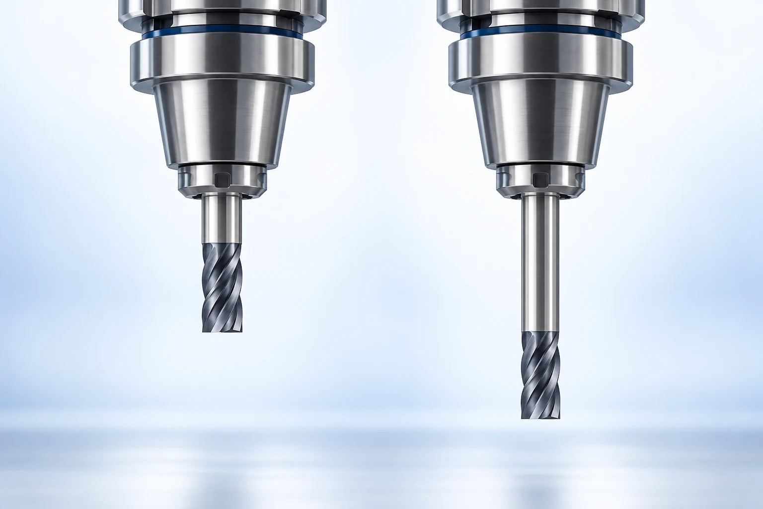
Do not confuse overall length with cutting length. A relieved neck may provide wall clearance below the holder without adding cutting edges. Confirm which section of the tool can actually contact the workpiece. The full assembly geometry should be represented when planning the cut. [1]
Runout and balance also answer different questions. Runout concerns how the tool rotates relative to its intended axis; balance concerns mass distribution during rotation. A balance designation alone does not demonstrate acceptable cutting-edge runout. Selection should also consider gripping requirements and coolant passage compatibility. Machine travel, spindle characteristics and tool-changing limits remain separate checks, covered in our CNC machining-center guide.
Choose a gripping system for the actual constraint
Different holder families solve different practical problems. Use the practical constraints below to narrow the choice. The selected product still needs the correct interface, shank compatibility and operating limits. [11]
- Collet chuck: different compatible collets accommodate different tool shanks. Match the collet range and assembly, and allow clearance for the retaining nut.
- Hydraulic holder: wrench-operated tool changes avoid a heating station. Available shank sizes, any sleeve requirements and the holder envelope still limit the choice.
- Shrink-fit holder: a slim design can improve access near a wall. It needs a compatible tool shank, heating equipment and a suitable tool-change routine.
- Mechanical milling chuck: assess the selected chuck’s grip rating, tool compatibility and body clearance for the milling operation. The family name alone does not establish suitability for a demanding cut.
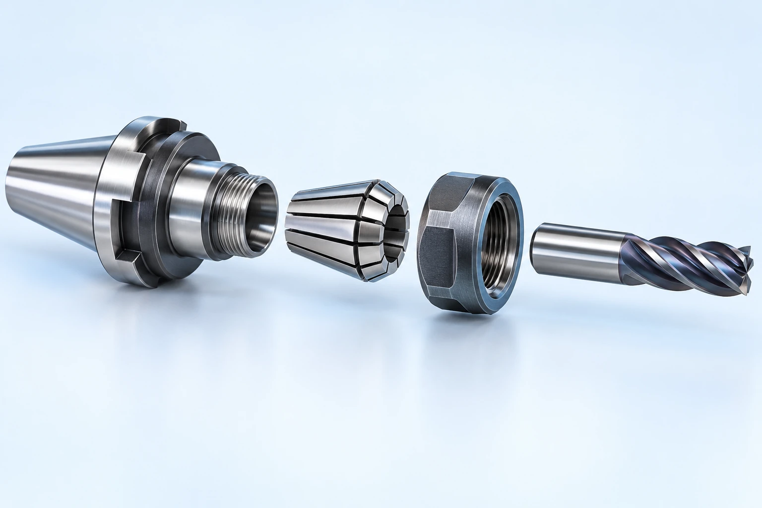
A collet chuck illustrates why the small components matter. The collet, retaining nut and tool shank form a matched assembly; one collet does not cover the entire diameter range of the holder system. REGO-FIX’s ER assembly instructions seat the collet in the nut before installing that nut on the holder. Follow the particular system’s assembly, insertion and tightening instructions rather than substituting a familiar routine from another holder. [12]
The sourcing question is whether a proposed holder solves the limiting condition. A slim assembly may be valuable beside a tall wall; rapid tool changes may matter more on a frequently changed job. Neither benefit establishes that the assembly will meet the part’s finish and dimensional requirements without verification.
Separate locating, supporting and clamping
A locator establishes position. A support carries load. A clamp keeps the workpiece seated against the intended contacts. Tightening a clamp cannot reliably correct a chip beneath a locating face or an inconsistent raw surface used as a reference.
For a simple prismatic part, the 3-2-1 locating concept uses three primary contacts, two secondary contacts and one end contact to establish its position. It is a design principle, not a requirement to install six separate pins on every fixture. Redundant or conflicting contacts can prevent consistent seating. Carr Lane’s locating and clamping guide also emphasizes chip clearance and directing clamping force into supported regions. [5]
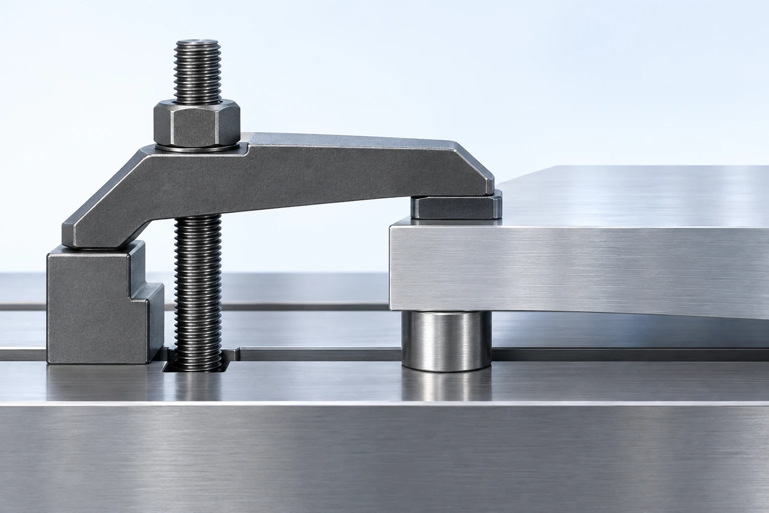
Consider a bracket with a thick mounting pad and a thin web. Holding the pad and pressing the web are different mechanical situations even if the same clamp is used. The process plan must account for the actual contact area, force direction and permitted marking. A cosmetic face or a sealing land may require a different contact location from an unfinished stock surface.
Location also needs a relationship to the drawing’s datums. A convenient stock edge can be useful for an early operation, but the plan must explain how the finished features will ultimately be controlled relative to the required references.
Compare workholding by the part and repeat job
The best holding method is the one that provides usable contact, cutting access and a practical loading routine for the job. A dedicated fixture is not automatically justified for a one-off part; a general-purpose vise is not automatically economical for a recurring awkward shape.
| Part-holding arrangement | Useful application | When to reconsider it |
|---|---|---|
| Vise with standard jaws | Prismatic stock with accessible gripping faces | Too little usable grip or jaws blocking the next feature |
| Chuck or collet | Rotational work with a suitable gripping diameter | Short engagement or a thin wall that deforms under the chosen grip |
| Dedicated locating fixture | Repeated complex parts or controlled datum transfer | Too little repeat demand or frequent changes to locating features |
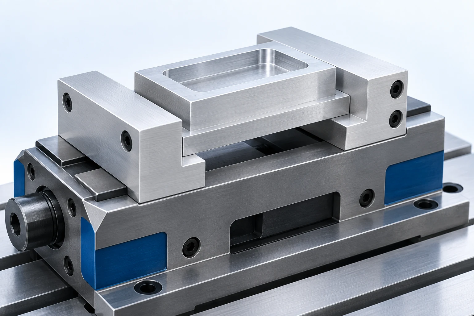
Soft jaws are useful because their contact shape can be machined to suit the part, not because the word “soft” guarantees an unmarked surface. Their shaped contacts can support repeat location of a shaped or partly finished part. Reassess them when a revision no longer matches the jaw cavity or the finished surfaces cannot accept that contact. The proposed contacts still need to avoid critical sealing or cosmetic areas. Likewise, a round part does not automatically belong in a collet: its available gripping diameter, unsupported length and wall stiffness can make another arrangement more practical.
A pallet or zero-point interface supports repeat mounting of a fixture or workholding assembly. This quick-change interface acts between assemblies; it does not replace the mechanism that restrains the part. Jergens’ modular workholding guidance illustrates this distinction between mounting and workpiece access. Evaluate both levels when comparing a palletized setup. [6]
For repeat orders, document the fixture revision, locating surfaces and replaceable contacts alongside the part revision. A drawing change that moves a hole may leave the fixture usable; one that removes a gripping land may not. The economic question is how much useful setup work survives the next batch, rather than whether the fixture can physically be stored.
Calculate what reusable tooling must save
Suppose a fixture costs an additional $240 and saves 3 minutes per accepted part compared with an existing method. Value that time at an assumed $80 per hour, holding all other costs and yield equal. The saving is 3 ÷ 60 × $80 = $4 per part; the extra fixture cost is recovered after $240 ÷ $4 = 60 parts.
At 20 parts, the time saving is only $80. At 100 parts, it is $400, leaving $160 after the extra fixture expense. A real comparison must also include fixture design, verification, maintenance and any difference in reject or rework costs. A fast loading cycle is valuable only if it repeatedly produces acceptable parts.
Treat speed, feed and rigidity as connected choices
Tool suppliers’ cutting data provide a starting point for a defined material and operation. Applying those data requires the actual tool engagement, projection, available machine performance and holding arrangement. A speed recommendation does not establish that a thin wall or marginal grip can withstand the resulting cut.
For milling, the programmed feed relationship is:
Feed rate (mm/min) = feed per tooth (mm/tooth) × spindle speed (rev/min) × number of effective cutting teeth. [7]
Take a hypothetical four-tooth cutter at 6,000 rpm and 0.04 mm per tooth. The corresponding feed is 0.04 × 6,000 × 4 = 960 mm/min. If spindle speed is reduced to 3,000 rpm while feed stays at 960 mm/min, programmed feed per tooth becomes 0.08 mm. It doubles.
These numbers illustrate the relationship, not recommended settings. Actual chip thickness also depends on engagement and cutter geometry. The example explains why “slow the spindle down” is incomplete advice: other conditions may change in an unfavorable direction. Likewise, reducing feed excessively can cause rubbing instead of solving a vibration problem. Investigate the assembly, engagement and workpiece support before treating one override as a universal cure. [4]
Provide a path for chips and the appropriate fluid
Tooling selection includes what happens to the material after it becomes a chip. A pocket surrounded by fixture elements has a different exit path from an open edge. Look for places where chips can be trapped, recut or deposited on locating contacts during loading. Nozzle location should be assessed with the real holder and clamps present.
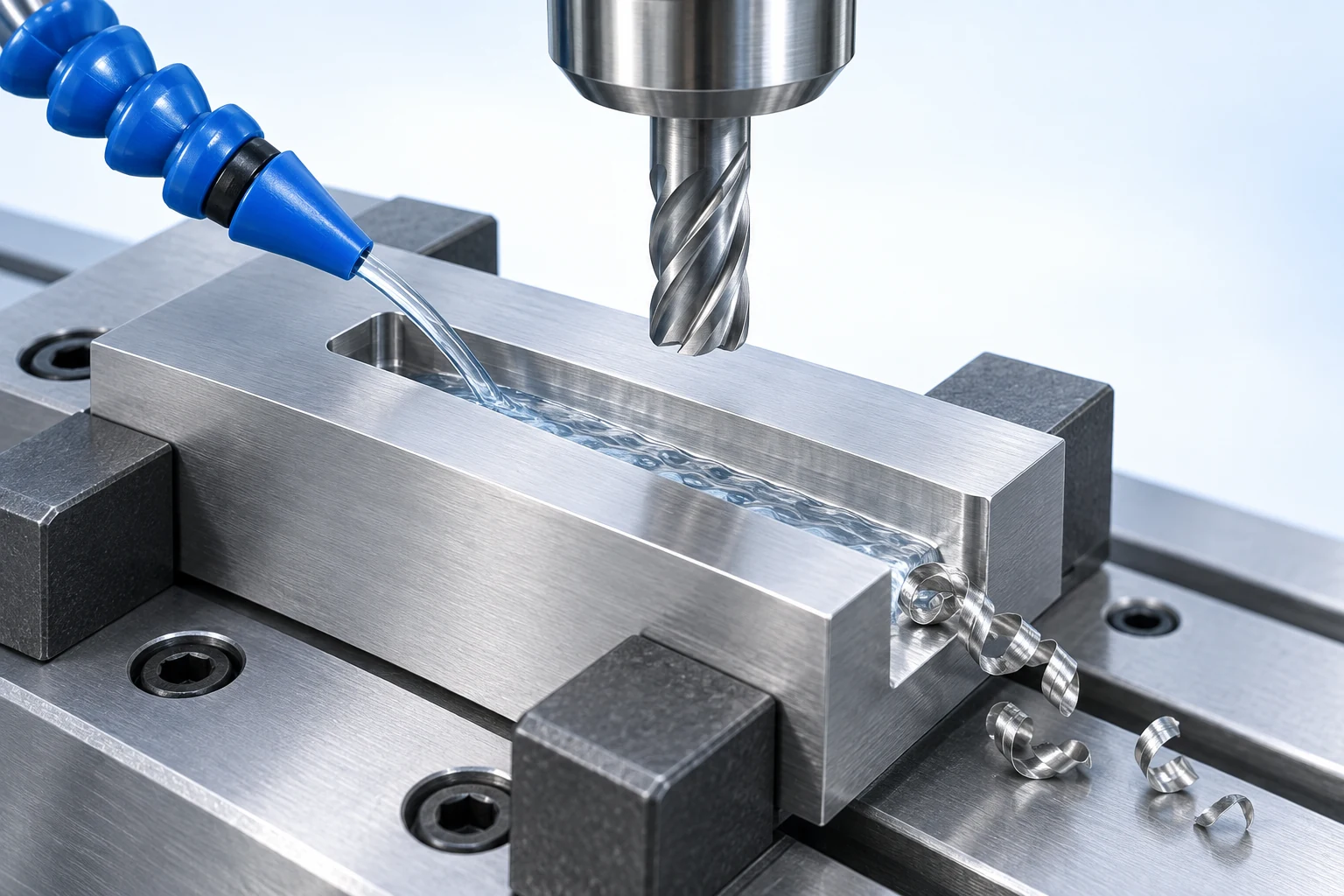
More coolant is not a universal answer. In interrupted milling, thermal cycling matters, and an unsuitable wet-cutting strategy can contribute to thermal cracking. Other material and finishing applications benefit from lubrication, cooling or improved chip evacuation. Follow the guidance for the chosen tool, material and operation, then confirm delivery can reach the working region. Sandvik Coromant discusses these competing conditions in Dry milling or with cutting fluid. [8]
The setup should make cleaning and reseating practical between parts. A chip-control problem can become a location problem on the next loading, even when the preceding part’s cutting cycle appeared normal.
Plan access throughout the machining sequence
A setup must work after stock has been removed, not only when the initial billet is clamped. Roughing can remove the surface intended for a later grip. Finishing an outside wall can expose the jaws to the next toolpath. Back-face features can require a second setup even when most of the part is accessible from above.
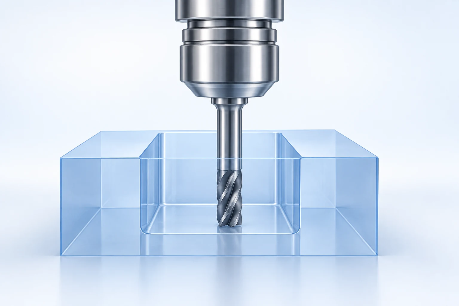
CAM verification should use the intended tool assembly, stock and fixture geometry, with machine motion included where the software supports it. Autodesk distinguishes toolpath simulation from verification involving the machine’s kinematics and configuration. Missing clamps or an inaccurate holder model leave gaps in the check. [9]
A collision-free model does not prove physical grip, cutting stability or finished accuracy. It answers a geometry and motion question within the model’s scope. The process still needs a valid locating scheme and a way to carry required relationships across setups. Our machining-process selection guide connects those operations with other manufacturing steps.
Measure the tool, locate the part and verify the result
Tool setting establishes quantities such as tool length and radius or diameter; suitable systems can also check for a broken tool. Workpiece probing can establish position and measure selected features. These functions serve different purposes, as Renishaw’s tool-setting and probing references describe. [10]
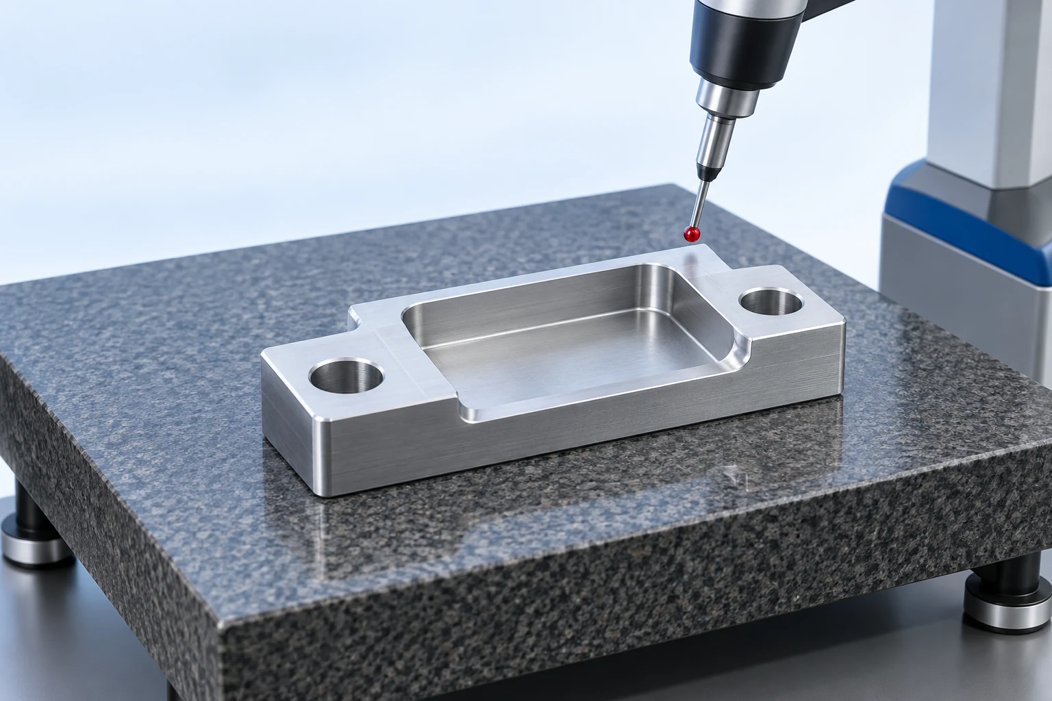
A correct tool offset does not establish that the part is correctly located, and a probed work origin does not prove that it stays seated during cutting. Acceptance should address the drawing’s dimensions, geometric relationships and surface requirements using an appropriate measurement plan.
For a flexible component, consider its state when measured. A wall or base held flat during machining may change shape after release. Where the drawing requires evaluation in an unrestrained condition, measurements taken only while the part is clamped can miss the relevant result. Conversely, an explicitly specified restrained condition should be respected. The measurement condition belongs in the plan, alongside the feature being checked.
Example: plan a stepped bracket as a complete job
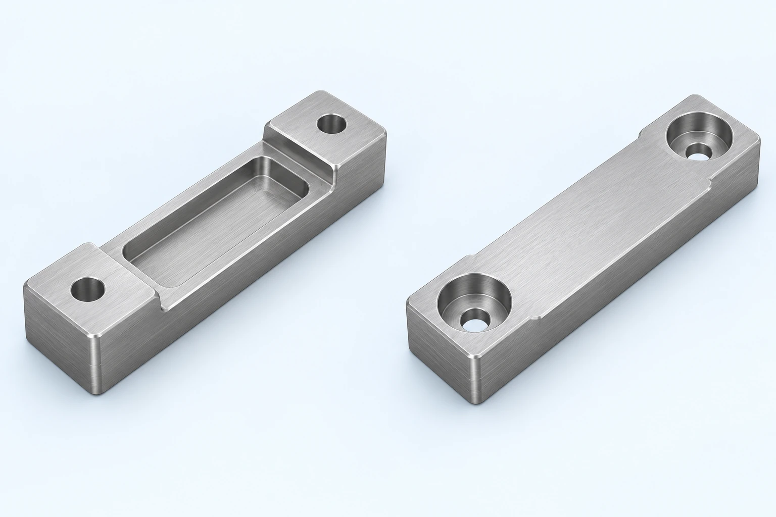
Consider a hypothetical rectangular bracket with a central top pocket, two raised end pads and two mounting holes counterbored from underneath. Assume the finished underside is the primary mounting reference, with one side and one end providing the remaining location references. The important relationships include top-pad height from the underside, pocket position, and alignment between each mounting hole and its counterbore.
First setup: create the references needed after the flip
Start with stock that leaves a usable gripping band for the first vise setup. Orient the future underside upward. Face that mounting surface, machine its accessible counterbores and through holes, and establish the accessible portions of the side and end that will locate the next operation. The stock and toolpaths must leave enough contact for the current grip until cutting in this orientation is complete.
Before releasing the part, establish that the new reference surfaces are usable and that the underside features are complete. A burr at an edge or a chip trapped during the next loading can defeat an otherwise sensible transfer. A reference face need not be cosmetically polished, but it must satisfy the applicable drawing requirement and provide the intended contact.
Second setup: seat the mounting face and expose the top
Flip the workpiece onto supports contacting sound areas of the finished underside. Provide relief beneath the counterbores, and remove burrs from locating contacts so the part rests on its intended supports. Locate against the prepared side and end. The jaws must grip the remaining robust side regions while leaving the top pads, pocket and tool approach accessible; shaped jaws are one option if standard jaws cannot do that.
Now finish the top pads and central pocket using the established underside as the height reference. This makes the critical relationship between mounting face and top geometry explicit. The setup is unsuitable if machining the pocket removes material needed to resist the remaining cuts. Its supports must contact solid regions of the underside that remain throughout this operation. Those conflicts require a changed sequence or fixture, not just a different work offset.
Assign tools and inspection to specific features
Use the pocket’s open area, corner geometry and depth to assign roughing and finishing tools. A smaller finishing cutter may reach the corners left by the rougher, but its holder still needs clearance above the pocket. The counterbores were machined with the underside facing upward in the first setup. The route obtains the required approach direction by orienting that face toward the spindle; extra projection on a conventional straight tool would not provide the same access from the opposite face.
Final inspection should address the finished part’s relationships, not just separate toolpath dimensions. Check the top-pad height relative to the mounting face, the required pocket location and the mounting-hole/counterbore relationship using the drawing’s references. If the first accepted part passes, that validates the observed result; repeat loading and tool changes still need the controls described below.
A useful quotation makes the part requirements and proposed reusable tooling distinguishable. Provide the drawing, material condition, quantities and relevant acceptance needs; the CNC machining RFQ checklist covers that handoff. For this bracket, the valuable discussion is which contacts and reference surfaces make both operations reliable, and which fixture work can be reused on the next order.
Keep the setup consistent beyond the first part
Repeated production introduces changes that an initial acceptance check cannot cover. Loading a new blank, reinstalling jaws and replacing a cutter are different events. Each can disturb a different part of the setup, so a single instruction to “reuse the offsets” is inadequate.
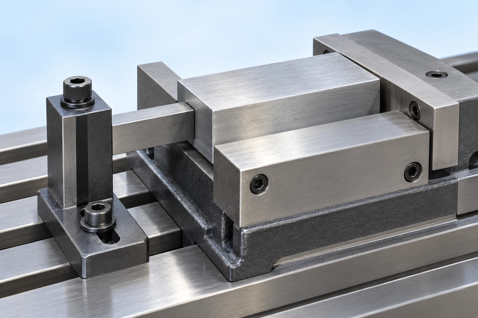
- Loading another blank: make the locating contacts and stop position identifiable and keep them clear. The workpiece should meet the intended references before cutting starts.
- Reinstalling jaws or a fixture: verify the location again rather than assuming the saved work origin remains valid. The stored setup record should identify the jaw or fixture revision and the reference features it uses.
- Replacing a tool: check the quantities affected by that change, such as assembled length and cutting radius, before relying on the previous offsets. The same catalog tool and turret or magazine position do not establish identical assembled geometry.
Renishaw’s tool-setting guidance identifies wear, damaged tools, incorrect geometry and contaminated interfaces as distinct sources of machining error. [13]
Measurement patterns can guide investigation. A shift affecting several features made by different tools suggests checking location and work offsets; gradual change in a feature cut by one tool suggests checking that tool and its cutting behavior. Neither pattern proves the cause. Compare measurements with the tool assembly, seating and process conditions before applying compensation.
Set inspection frequency and intervention limits from the part’s risk and demonstrated process stability. Renishaw’s process-control guidance uses defined compensation limits and alarms rather than unlimited offset changes. A tool offset should correct an understood, permissible change; it should not conceal a damaged edge or a workpiece that is moving in the fixture. [14]
Common tooling and workholding questions
Should a buyer specify a particular cutting-tool brand?
Usually the drawing should establish the required result, leaving tool selection to the manufacturing plan. A validated process, contractual requirement or controlled qualification may require a particular tool. Make that constraint explicit rather than assuming a preferred brand is necessary for every suitable process.
Who owns a fixture charged separately on an order?
A separate tooling line does not settle ownership, storage, maintenance or transfer rights. Those are commercial terms to agree with the supplier. Also clarify whether the quoted item is a dedicated fixture, replaceable jaws, consumable cutting tools or engineering work; the same label can cover different deliverables.
Can the same setup be reused for another material?
Sometimes the geometry and location scheme remain useful, but the cutting tools, loads, chip behavior and permitted contact marks may change. Treat the new material and condition as a process change requiring review. An unchanged CAD model is not enough to approve the old machining setup.
Technical references
- Harvey Performance, The Anatomy of an End Mill — tool profiles, flute space and length definitions.
- Sandvik Coromant, How to choose correct turning insert — insert geometry and application selection.
- BIG DAISHOWA, CNC Tool Holders — spindle interfaces, gripping systems and retention compatibility.
- Sandvik Coromant, How to reduce vibration in milling — assembly rigidity and cutting-condition interactions.
- Carr Lane, Guide To Locating & Clamping Principles — location, support, chip clearance and clamping.
- Jergens, 5-Axis Knowledge Center — Overview — modular workholding and access.
- Sandvik Coromant, Formulas and definitions for milling — METRIC, H79 — programmed feed relationship.
- Sandvik Coromant, Dry milling or with cutting fluid — interrupted cutting and application-dependent fluid use.
- Autodesk Fusion, Simulation for manufacturing — verification scope and machine configuration.
- Renishaw, Tool setting technology and Probing and tool measurement systems for machine tools — tool and workpiece measurement functions.
- BIG DAISHOWA, Hydraulic Tool Holders, Shrink Fit Tool Holders and Total Tooling System General Catalog, Vol. 10 — changing methods, slim access and mechanical milling-chuck design.
- REGO-FIX, ER System and ER Floating Chuck brochure, ER assembly instructions — compatible components and collet/nut assembly.
- Renishaw, Tool setters and broken tool detectors — tool geometry, wear and damaged-tool checks.
- Renishaw, IPC — Intelligent Process Control — measurement-based compensation and defined intervention limits.



